EP2018952A1 - Verfahren zur Gewinnung eines Produkts aus einem thermoplastischen Material und entsprechendes Produkt - Google Patents
Verfahren zur Gewinnung eines Produkts aus einem thermoplastischen Material und entsprechendes Produkt Download PDFInfo
- Publication number
- EP2018952A1 EP2018952A1 EP07380399A EP07380399A EP2018952A1 EP 2018952 A1 EP2018952 A1 EP 2018952A1 EP 07380399 A EP07380399 A EP 07380399A EP 07380399 A EP07380399 A EP 07380399A EP 2018952 A1 EP2018952 A1 EP 2018952A1
- Authority
- EP
- European Patent Office
- Prior art keywords
- thermoplastic material
- mold
- process according
- reinforcing member
- carrier support
- Prior art date
- Legal status (The legal status is an assumption and is not a legal conclusion. Google has not performed a legal analysis and makes no representation as to the accuracy of the status listed.)
- Granted
Links
- 239000012815 thermoplastic material Substances 0.000 title claims abstract description 155
- 238000000034 method Methods 0.000 title claims abstract description 98
- 238000000151 deposition Methods 0.000 claims abstract description 11
- 229920005992 thermoplastic resin Polymers 0.000 claims abstract description 9
- 238000004519 manufacturing process Methods 0.000 claims abstract description 5
- 230000003014 reinforcing effect Effects 0.000 claims description 107
- 239000000463 material Substances 0.000 claims description 63
- 229920001187 thermosetting polymer Polymers 0.000 claims description 3
- 238000009966 trimming Methods 0.000 claims description 3
- 238000010521 absorption reaction Methods 0.000 claims description 2
- 239000000047 product Substances 0.000 description 32
- 238000002347 injection Methods 0.000 description 20
- 239000007924 injection Substances 0.000 description 20
- 239000004033 plastic Substances 0.000 description 16
- 238000009826 distribution Methods 0.000 description 13
- 230000000295 complement effect Effects 0.000 description 5
- 238000001125 extrusion Methods 0.000 description 5
- 230000006835 compression Effects 0.000 description 4
- 238000007906 compression Methods 0.000 description 4
- 230000008878 coupling Effects 0.000 description 4
- 238000010168 coupling process Methods 0.000 description 4
- 238000005859 coupling reaction Methods 0.000 description 4
- 230000005484 gravity Effects 0.000 description 4
- 238000000465 moulding Methods 0.000 description 4
- 230000002787 reinforcement Effects 0.000 description 4
- 229920001169 thermoplastic Polymers 0.000 description 4
- 239000004416 thermosoftening plastic Substances 0.000 description 4
- 239000007795 chemical reaction product Substances 0.000 description 3
- 238000001816 cooling Methods 0.000 description 3
- 238000005265 energy consumption Methods 0.000 description 3
- 238000010438 heat treatment Methods 0.000 description 3
- 230000006641 stabilisation Effects 0.000 description 3
- 238000011105 stabilization Methods 0.000 description 3
- 238000005520 cutting process Methods 0.000 description 2
- 230000007547 defect Effects 0.000 description 2
- 238000001746 injection moulding Methods 0.000 description 2
- 238000002844 melting Methods 0.000 description 2
- 230000008018 melting Effects 0.000 description 2
- 230000035515 penetration Effects 0.000 description 2
- 238000005303 weighing Methods 0.000 description 2
- 206010003830 Automatism Diseases 0.000 description 1
- 206010052128 Glare Diseases 0.000 description 1
- 239000004809 Teflon Substances 0.000 description 1
- 229920006362 Teflon® Polymers 0.000 description 1
- 230000001133 acceleration Effects 0.000 description 1
- 239000000654 additive Substances 0.000 description 1
- 230000000996 additive effect Effects 0.000 description 1
- 230000015556 catabolic process Effects 0.000 description 1
- 238000006731 degradation reaction Methods 0.000 description 1
- 230000006866 deterioration Effects 0.000 description 1
- -1 dimensions Substances 0.000 description 1
- 239000000835 fiber Substances 0.000 description 1
- 239000000945 filler Substances 0.000 description 1
- 230000004313 glare Effects 0.000 description 1
- 230000000977 initiatory effect Effects 0.000 description 1
- 238000009434 installation Methods 0.000 description 1
- 238000009413 insulation Methods 0.000 description 1
- 230000010354 integration Effects 0.000 description 1
- 239000007788 liquid Substances 0.000 description 1
- 239000002184 metal Substances 0.000 description 1
- 238000012856 packing Methods 0.000 description 1
- 235000011837 pasties Nutrition 0.000 description 1
- 239000011148 porous material Substances 0.000 description 1
- 238000007493 shaping process Methods 0.000 description 1
- 239000000243 solution Substances 0.000 description 1
- 230000037303 wrinkles Effects 0.000 description 1
Images









Classifications
-
- B—PERFORMING OPERATIONS; TRANSPORTING
- B29—WORKING OF PLASTICS; WORKING OF SUBSTANCES IN A PLASTIC STATE IN GENERAL
- B29C—SHAPING OR JOINING OF PLASTICS; SHAPING OF MATERIAL IN A PLASTIC STATE, NOT OTHERWISE PROVIDED FOR; AFTER-TREATMENT OF THE SHAPED PRODUCTS, e.g. REPAIRING
- B29C31/00—Handling, e.g. feeding of the material to be shaped, storage of plastics material before moulding; Automation, i.e. automated handling lines in plastics processing plants, e.g. using manipulators or robots
- B29C31/04—Feeding of the material to be moulded, e.g. into a mould cavity
-
- B—PERFORMING OPERATIONS; TRANSPORTING
- B29—WORKING OF PLASTICS; WORKING OF SUBSTANCES IN A PLASTIC STATE IN GENERAL
- B29C—SHAPING OR JOINING OF PLASTICS; SHAPING OF MATERIAL IN A PLASTIC STATE, NOT OTHERWISE PROVIDED FOR; AFTER-TREATMENT OF THE SHAPED PRODUCTS, e.g. REPAIRING
- B29C31/00—Handling, e.g. feeding of the material to be shaped, storage of plastics material before moulding; Automation, i.e. automated handling lines in plastics processing plants, e.g. using manipulators or robots
- B29C31/04—Feeding of the material to be moulded, e.g. into a mould cavity
- B29C31/08—Feeding of the material to be moulded, e.g. into a mould cavity of preforms to be moulded, e.g. tablets, fibre reinforced preforms, extruded ribbons, tubes or profiles; Manipulating means specially adapted for feeding preforms, e.g. supports conveyors
-
- B—PERFORMING OPERATIONS; TRANSPORTING
- B29—WORKING OF PLASTICS; WORKING OF SUBSTANCES IN A PLASTIC STATE IN GENERAL
- B29C—SHAPING OR JOINING OF PLASTICS; SHAPING OF MATERIAL IN A PLASTIC STATE, NOT OTHERWISE PROVIDED FOR; AFTER-TREATMENT OF THE SHAPED PRODUCTS, e.g. REPAIRING
- B29C43/00—Compression moulding, i.e. applying external pressure to flow the moulding material; Apparatus therefor
- B29C43/02—Compression moulding, i.e. applying external pressure to flow the moulding material; Apparatus therefor of articles of definite length, i.e. discrete articles
- B29C43/18—Compression moulding, i.e. applying external pressure to flow the moulding material; Apparatus therefor of articles of definite length, i.e. discrete articles incorporating preformed parts or layers, e.g. compression moulding around inserts or for coating articles
- B29C43/183—Compression moulding, i.e. applying external pressure to flow the moulding material; Apparatus therefor of articles of definite length, i.e. discrete articles incorporating preformed parts or layers, e.g. compression moulding around inserts or for coating articles the preformed layer being a lining, e.g. shaped in the mould before compression moulding, or a preformed shell adapted to the shape of the mould
-
- B—PERFORMING OPERATIONS; TRANSPORTING
- B29—WORKING OF PLASTICS; WORKING OF SUBSTANCES IN A PLASTIC STATE IN GENERAL
- B29C—SHAPING OR JOINING OF PLASTICS; SHAPING OF MATERIAL IN A PLASTIC STATE, NOT OTHERWISE PROVIDED FOR; AFTER-TREATMENT OF THE SHAPED PRODUCTS, e.g. REPAIRING
- B29C43/00—Compression moulding, i.e. applying external pressure to flow the moulding material; Apparatus therefor
- B29C43/32—Component parts, details or accessories; Auxiliary operations
- B29C43/34—Feeding the material to the mould or the compression means
-
- B—PERFORMING OPERATIONS; TRANSPORTING
- B29—WORKING OF PLASTICS; WORKING OF SUBSTANCES IN A PLASTIC STATE IN GENERAL
- B29K—INDEXING SCHEME ASSOCIATED WITH SUBCLASSES B29B, B29C OR B29D, RELATING TO MOULDING MATERIALS OR TO MATERIALS FOR MOULDS, REINFORCEMENTS, FILLERS OR PREFORMED PARTS, e.g. INSERTS
- B29K2105/00—Condition, form or state of moulded material or of the material to be shaped
- B29K2105/06—Condition, form or state of moulded material or of the material to be shaped containing reinforcements, fillers or inserts
-
- B—PERFORMING OPERATIONS; TRANSPORTING
- B29—WORKING OF PLASTICS; WORKING OF SUBSTANCES IN A PLASTIC STATE IN GENERAL
- B29K—INDEXING SCHEME ASSOCIATED WITH SUBCLASSES B29B, B29C OR B29D, RELATING TO MOULDING MATERIALS OR TO MATERIALS FOR MOULDS, REINFORCEMENTS, FILLERS OR PREFORMED PARTS, e.g. INSERTS
- B29K2105/00—Condition, form or state of moulded material or of the material to be shaped
- B29K2105/25—Solid
- B29K2105/253—Preform
- B29K2105/256—Sheets, plates, blanks or films
-
- B—PERFORMING OPERATIONS; TRANSPORTING
- B29—WORKING OF PLASTICS; WORKING OF SUBSTANCES IN A PLASTIC STATE IN GENERAL
- B29L—INDEXING SCHEME ASSOCIATED WITH SUBCLASS B29C, RELATING TO PARTICULAR ARTICLES
- B29L2031/00—Other particular articles
- B29L2031/30—Vehicles, e.g. ships or aircraft, or body parts thereof
- B29L2031/3005—Body finishings
- B29L2031/3041—Trim panels
Definitions
- the invention is comprised in the field of the manufacture of thermoplastic resin parts, for example, for their use as automotive vehicle components.
- thermoplastic resin is injected at high temperature and high pressure in a closed mold, allowing complex shapes to be obtained.
- high pressure and temperature injection techniques very compact and very rigid parts can be obtained, so many times reinforcing elements are not needed.
- the plastic part In some cases (as in the case of roof panels or door panels for automotive vehicles), the plastic part must incorporate a lining layer on at least one of the two faces of the obtained part (generally arranged on the "visible face", i.e. on the face of the product that is visible to the user during conventional product use). In order for this lining layer to adhere to the plastic part, the lining layer is generally placed in the mold and then the thermoplastic material is injected. This has the drawback that it is not possible to use any lining material since many materials may degrade (for example due to burning or glares which deteriorate their appearance or involve the loss of their initial properties) due to the high temperatures of the injection.
- the high pressure of the injection may further break the lining material.
- the movement of the plastic material flowing from the injection nozzle throughout the mold may furthermore cause the lining layer to move, wrinkle or become detached, dragged by the movement of the plastic material, possibly changing the final appearance of the part.
- the injection processes can be carried out in a closed mold or in an open mold (in which case the injection is carried out in two steps: first part of the material is injected with the mold open, then the mold is closed and the injection is then finished).
- thermoplastic parts Another technique that can be used for producing thermoplastic parts is called open mold compression. This technique is traditionally based on introducing the plastic material in an open mold, closing with the corresponding upper mold and applying a closing pressure. In this technique, the pressures are not as high as in injection molding processes, and the plastic material is usually at a lower temperature than the temperature used in injection processes.
- thermoplastic material feed hoppers thermoplastic material heating means and other devices that do not have to be moved and, furthermore, an arm by means of which the thermoplastic material is introduced in the mold, which arm generally incorporates heating means to prevent the material from cooling down and a thermoplastic material driving system, for example a worm screw.
- this arm would have to move and would still be a very large and heavy element.
- the mold generally incorporates guiding columns making it difficult for the arm of the metering machine to access the cavity of the mold to be filled with the thermoplastic product (the columns are usually arranged between the lower part and the upper part of the mold so as to allow the guided movement of the upper part for the pressure closing of the mold).
- These reinforcing members can consist of, for example, meshes or screens which are placed inside the open mold, then introducing the plastic material in the mold on the screen or mesh.
- a first aspect of the invention relates to a process for the manufacture of thermoplastic resin parts, comprising the steps of:
- step a) comprises the steps of:
- the carrier support can be handled by using for example any robot or conventional manipulator, or even by means of manual handling in the cases in which it is more advantageous.
- a controlled distribution of the material at each point or area of the carrier support can thus be carried out, which is reflected in the subsequent arrangement of the material in the cavity of the mold.
- the machine providing the material is heavy, which makes moving it difficult, slow and tedious, as well as large, therefore its mobility is very limited in a reduced area and surrounded by physical obstacles, such as the obstacle surrounding the cavity of the mold.
- moving the mobile part of an extrusion machine weighing several hundred kilos entails an installation that is large, complex, custom-made, difficult to install and difficult to modify or move, in comparison with the simplicity, versatility, mobility and configurability of the automatism that is necessary for moving the carrier support, which can be a light tray with a few kilos of material, weighing no more than 10 kg in total for example.
- thermoplastic material that is used can be of many types and can completely or partially comprise recycled material and/or different types of filler, reinforcing and/or additive material, as in the previously described processes.
- the carrier support can have any suitable shape and the optimal support can be chosen depending on the other features of the process.
- the carrier support can be an open or closed type support, for example it can be a simple tray, a box or a container of any type, open or closed (for example with a cover).
- the cover could be used for example to allow overturning the carrier support and also to prevent the thermoplastic material from falling out of the carrier support, for example during the movements of the carrier support, which movements may involve strong accelerations of the carrier support.
- the carrier support can be deposited in the cavity of the mold along with the thermoplastic material, or the thermoplastic material can be removed from the carrier support, for example by gravity (tilting the carrier support), when the thermoplastic material is introduced in the cavity of the mold.
- the carrier support can have a substantially planar or "two-dimensional" "tray”-type shape.
- the temperature of the thermoplastic material can be above the Vicat softening temperature of the thermoplastic material. This can be important if, for example, the material has to pass through or enter holes or perforations in a reinforcing member housed in the mold, to assure proper integration of such reinforcing member in the obtained product.
- the temperature of the thermoplastic material can be under the melting point of the thermoplastic material. This can be advantageous because it can reduce the energy consumption and reduce the risk that defects due to degradation occur when, for example, there is a lining layer integrated with the product in the mold. Furthermore, the fact that the thermoplastic material initially has a low temperature helps in that the material does not drip through the holes of the carrier support, when such holes exist, before applying the pressure in step b).
- the temperature of the thermoplastic material can be above the melting point of the thermoplastic material in some embodiments of the invention, for example when lining layers are not used.
- thermoplastic material can be distributed on the carrier support such that there is more material present in some areas of its surface than in other areas.
- the distribution can be done depending on the layout of the product to be obtained so that, for example, there is enough thermoplastic material to create members such as turrets, etc.
- the thermoplastic material can be deposited on the carrier support from at least one outlet nozzle of a thermoplastic material extrusion or metering machine.
- At least one manipulator or robotic arm can be used to move the carrier support with regard to said outlet nozzle during the application of the thermoplastic material, such that the distribution of the thermoplastic material on the carrier support is determined by movements made by said at least one manipulator or robotic arm during the application of the thermoplastic material.
- the same robotic arm (or arms) can be used to then convey the carrier support with the thermoplastic material to the mold.
- thermoplastic material and/or several types of thermoplastic material can logically be applied such that, for example, different areas of the carrier support have different thermoplastic materials and/or different amounts of thermoplastic material and/or different ratios between the different thermoplastic materials.
- the robotic arm can move the carrier support between several nozzles supplying different thermoplastic materials before introducing the thermoplastic material in the cavity of the mold.
- step a1) the thermoplastic material is deposited from a fixed dispensing member, and the carrier support moves, by means of a manipulator (a robot for example), with regard to said fixed dispensing member, such that the thermoplastic material is distributed in a substantially predetermined manner on the carrier support.
- a manipulator a robot for example
- a suitable distribution of the material on the carrier support can thus be obtained without needing to move the dispensing member, which can be useful, for example, for simplifying the general structure of the system used.
- thermoplastic material is deposited from a movable dispensing member, and the carrier support moves, by means of a manipulator, in synchronization with the dispensing member, such that the thermoplastic material is distributed in a substantially predetermined manner on the carrier support.
- a quicker distribution of the thermosetting material for example, can thus be obtained.
- the carrier support is heated during steps a1) and/or a2), such that the thermosetting material has a temperature exceeding a predetermined threshold when it is deposited in the cavity of the mold. Excessive cooling of the material during steps a1) and/or a2) that may negatively affect the result of the molding process can thus be prevented.
- the carrier support and/or the thermoplastic material can be heated or preheated. A suitable degree of fluidity or softening of the thermoplastic material can thus be assured, improving its distribution in the cavity of the mold during step b). This can be important, for example, if the time between the depositing of the thermoplastic material on the carrier support and the application of pressure in step b) is long.
- thermoplastic material when it is applied on the carrier support, the metering time and the type of thermoplastic material that is used.
- This heating prior to introducing the thermoplastic material in the cavity of the mold can be carried out in many ways, for example by means of infrared, hot air, etc.
- the process may additionally comprise the step of depositing at least one reinforcing member in the cavity of the mold, such that it is an integral part of the obtained product, said reinforcing member having a laminar or substantially laminar shape.
- the features of the obtained product can thus be improved in terms of, for example, its strength, rigidity, etc.
- this reinforcing member can be cut from a strip in synchronization with the rest of the process.
- the reinforcing member can have larger dimensions than the cavity of the mold (at least in one or two dimensions), die-cutting the excess after shaping the part.
- the reinforcing member can have smaller dimensions than the cavity of the mold and be completely housed therein. In this case, there could be an area of the product without a reinforcing member.
- the reinforcing member is deposited in the cavity of the mold along with the thermoplastic material, for example the reinforcing member can be deposited on the carrier support before step a3).
- the reinforcing member can be deposited on the carrier support before step a3).
- a first part of the thermoplastic material can be deposited on the carrier support, then the reinforcing member can be deposited on said first part of the thermoplastic material, and then a second part of the thermoplastic material can be deposited on the reinforcing member.
- the reinforcing member can be placed in the cavity of the mold before the thermoplastic material is deposited in the cavity of the mold.
- the reinforcing member can be introduced in the cavity of the mold after step a3) but before step b).
- the reinforcing member is or forms part of the carrier support.
- This embodiment can be particularly advantageous because it allows carrying out the process without having to use an additional carrier support (which is not part of the product), simplifying the process and reducing the material costs.
- the amount of thermoplastic material that is deposited on the carrier support can be such that in combination with the way the molding process (step b)) is carried out, one or two larger surfaces of the reinforcing member are covered by the thermoplastic material once step b) is carried out. The reinforcing member is thus embedded, to a greater or lesser extent, in the thermoplastic material.
- the reinforcing member When the reinforcing member is part of the carrier support and/or when the thermoplastic material is deposited on the reinforcing member before it is introduced in the mold, it can be particularly important for the reinforcing member to be placed in the cavity of the mold such that the thermoplastic material does not move with regard to the reinforcing member. In such case, it can be appropriate for the reinforcing member to be introduced in the mold in correspondence with the position of the cavity of the mold and be deposited without breaking or moving. For example, the reinforcing member can be vertically lowered until making contact at its lowest point with the cavity of the mold before it is released.
- the reinforcing member along with the thermoplastic material, is overturned approximately 180 degrees about an approximately horizontal axis between step a1) and step a3).
- the thermoplastic material can be deposited on a larger upper surface of the carrier support/reinforcing member.
- the reinforcing member can be turned or overturned (for example approximately 180 degrees according to a substantially horizontal axis) such that said first upper larger surface becomes a lower larger surface before the reinforcing member is introduced in the cavity of the mold. In other words, the reinforcing member is turned over such that the side with the thermoplastic material is facing downwards.
- the surface on which the thermoplastic material is deposited faces downwards and comes into contact with an inner surface of the cavity of the mold or with, for example, a sheet or lining material deposited on said inner surface.
- This can be appropriate when the "visible face" of the product is formed against said inner surface, for example so that said visible face does not reflect the (for example mesh or screen) "structure" of the reinforcing member.
- This can be particularly relevant when the product has a non-lined visible face (in which the thermoplastic material is visible on said visible face), but also in products with a lined visible face.
- the reinforcing member, along with the thermoplastic material can be turned between step a1) and step a3) such that it has a position perpendicular to a closing direction of the mold.
- This can be useful, for example, when the thermoplastic material is deposited on the reinforcing member in a horizontal state but the mold is a vertical mold closing in the horizontal direction.
- the reinforcing member can have a structure in the form of mesh (in this document the expression "in the form of mesh” means that it is a reinforcing member in the form of mesh or screen with a plurality of holes traversing the member from one larger surface to another larger surface of the member; it is a member that can be laminar and more or less planar, and its thickness can be substantially less than its length and its width; the reinforcing member can be made from any suitable material, for example it can be a metal screen or a screen made of a plastic material, for example a thermoplastic, and/or it can be made of plant fibers, but it can also be made of another material, all in accordance with the desired features of the end product).
- the reinforcing member comprises a plurality of through holes.
- the reticular structure, mesh structure and/or structure with through holes makes it possible for the thermoplastic material to at least partially penetrate the holes and even be distributed on the opposite face of the reinforcing member in the molding process, improving the attachment between the thermoplastic material and the reinforcing member and assuring a good degree of coupling between the thermoplastic material and the reinforcing member.
- thermoplastic material in this manner, and with a reinforcing member or mesh with suitably sized and distributed holes (for example depending on the features of the process, including temperatures, pressures and cycle times, and the features of the thermoplastic material that is used), the viscosity and the surface tension of the thermoplastic material, in its melted or at least softened state, allows the material, in step a1), to be substantially deposited on the surface without "dripping" through the holes and without the reinforcing member becoming detached, during the time it takes to move the reinforcing member to the point where it is introduced in the cavity of the mold.
- the reinforcing member comprises on at least one surface a plurality of non-through holes.
- These perforations or non-through holes may allow the thermoplastic material to at least partially enter said holes, such that a stronger attachment or coupling between the reinforcing member and the thermoplastic material is obtained than what would have been obtained with a reinforcing member with a substantially smooth surface. Suitable penetration of the plastic material in said perforations or through holes or non-through holes occurs due to the pressure exerted on the thermoplastic material in the mold.
- the reinforcing member is pre-heated before coming into contact with the thermoplastic material.
- the cavity of the mold can be configured such that in step b), the thermoplastic material forms at least one functional member, for example selected from the group comprising: fixing turrets, cable fixing clamps, reinforcing members and impact absorption structures.
- the amount of thermoplastic material that is deposited on the carrier support can be controlled.
- the metering of the thermoplastic material in controlled amounts is advantageous since for example: it assures that the mold is correctly filed, covering the entire surface of the part with the material; it allows obtaining complex shapes in certain areas, creating functional members, i.e. areas of the part having their own functions and which in the state of the art are commonly independent parts which are assembled on the previously obtained plastic part, and/or ribs or reinforcements; and it reduces the risk of dragging a reinforcing or lining inside the mold.
- the amount of thermoplastic material that is deposited on the carrier support can be controlled such that in at least one area of the carrier support more thermoplastic material is deposited per surface unit than in another area of the carrier support.
- a distribution of the thermoplastic material on the carrier support that corresponds with the features of the product to be obtained is thus achieved, i.e. it is possible to deposit more material in the areas corresponding to the thicker areas in the product to be obtained, or in the areas corresponding to functional members requiring more material, etc.
- the material thus introduced in the mold may already have a distribution that is fairly consistent with the distribution the material will have in the product to be obtained, such that when the mold is closed, the "final shape" is given to this material, but it will not be necessary to move large amounts of the thermoplastic material from one area of the mold to another using pressure, in contrast with what occurs in an injection process of the type described above in relation to the state of the art.
- the cavity of the mold can be provided with positioning means for positioning additional insert parts.
- the cavity can be configured such that additional members, which can be integrated into the product in step b) and thus be part of the end product, can be placed therein in certain positions.
- At least one lining layer is introduced in the mold before step b), such that it is an integral part of the obtained product and such that it covers at least one part of a face of the obtained product.
- at least one lining layer in the cavity of the mold, for example before the thermoplastic material (with or without a reinforcing member) is introduced in the cavity of the mold, such that, for example, the lining layer is located between a larger surface of the reinforcing member and a contact surface of the mold. The direct attachment between the thermoplastic material, the reinforcing member, when such member is used, and the lining is thus facilitated.
- the lining layer can include a reinforcing layer that is embedded inside the obtained product.
- This reinforcing layer could be made from the same material as the lining layer and could replace the reinforcing member discussed above or it could be a complement to said reinforcing member.
- the process further comprises the steps of, after step c), cutting the excess material away from the obtained product.
- the process can be a process for obtaining a member for an automobile, for example a member selected from the group comprising: a door panel, a rear tray and a pillar trim.
- Another aspect of the invention relates to an object or product obtained or that can be obtained with the process described above.
- Figures 1A and 2A show how a manipulator 6 holds a carrier support 4 in the form of a tray (and which can be formed by a reinforcing member 7), which moves towards a metering machine.
- the carrier support receives, from a dispensing member 5 of the thermoplastics metering or extrusion machine, a certain amount of thermoplastic material 2 comprising one or more thermoplastic resins.
- the distribution of the thermoplastic material on the carrier support 4 is determined from the relative movement between the carrier support 4 and the dispensing member 5; for example, the robot or manipulator 6 can move the carrier support 4 with regard to a fixed dispensing member 5, or the manipulator 6 can move the carrier support 4 in synchronization with the movement of a mobile dispensing member 5, etc.
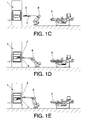
- the manipulator 6 moves said carrier support towards the mold 1 ( Figures 1C-1 D/2C-2D) and places ( Figures 1E and 2E ) the thermoplastic material 2 and optionally the carrier support 4, in the cavity 11 of the mold 1.
- the manipulator can overturn (for example by turning 180 degrees) the carrier support so that the thermoplastic material is facing "downwards" before depositing the carrier support 4 in the cavity 11, or it can tilt the carrier support 4 so that the thermoplastic material 2 falls inside the cavity 11 by gravity.
- the carrier support can be a tray with an upper surface having a low coefficient of friction (for example it can have an upper Teflon surface or the like), therefore the thermoplastic material can easily slide with regard to said surface.
- FIGS 9A-9C schematically show this "overturning" process in the event that the carrier support 4 is a reinforcing member 7.
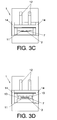
- FIGs 3A-3D schematically show a process in which the thermoplastic material 2 is first deposited in the cavity 11 of the mold 1 and then a reinforcing member 7 in the form of mesh is added on said thermoplastic material 2, ( Figure 3A ). Then the mold is closed ( Figure 3B ) and the material is compressed and distributed ( Figure 3C ), such that the reinforcing member 7 is embedded in the thermoplastic material 2, passing through the holes of the mesh.
- Figure 3D shows how the mold opens to remove the obtained product 3, with the reinforcing member 7 embedded in the thermoplastic material 2.
- the reinforcing member 7 has dimensions that are larger than those of the cavity 11 of the mold, whereby it projects with regard to the obtained product 3. Therefore, it may be necessary to trim the reinforcing member, which can be done with conventional trimming means. This trimming can be done after obtaining the product 3 in the step shown in Figure 3D , or even sooner, for example during step 3C.
- Figures 3A-3D also show the cylinders 12 the movement of which cause the mold to open and close, the guide cylinders 13 (which in the state of the art may make it difficult to introduce the thermoplastic material in the mold) and the columns 14 holding the upper part of the machinery of the mold over the lower part of said machinery.
- the guide cylinders 13 which in the state of the art may make it difficult to introduce the thermoplastic material in the mold
- the columns 14 holding the upper part of the machinery of the mold over the lower part of said machinery.
- Figures 4A-4D show a similar process, but in which the reinforcing member 7 is placed in the cavity 11 of the mold 1 before the thermoplastic material 2 is deposited in said cavity.
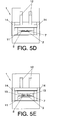
- Figures 5A-5E shows a process similar to that of Figures 3A-3D , but with a first step that is shown in Figure 5A and comprising the placement of a sheet 8 which will form a lining layer 8 of the product 3 extracted at the end of the process ( Figure 5E ).
- This lining layer 8 is placed on a lower surface of the mold, and the thermoplastic material 2 is placed on top of it ( Figure 5B ).
- gripping and centering means can be used which for example peripherally hold the lining so as to maintain its tension. This can be done inside the mold, before the thermoplastic material 2 is deposited.
- the gripping means can be, for example, means provided in the actual mold (by means of clamps or any other device) or they can comprise an outer member that is introduced in the mold with the lining (for example a frame with a series of needles traversing and holding the lining along its periphery). These means must keep the lining stretched or tensed while the thermoplastic material 2 is being poured.
- the lining projects from the thermoplastic material (which is the case in the example shown in Figures 5A-5E ), it can be trimmed similar to that discussed above in relation to the reinforcing member.
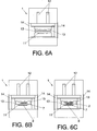
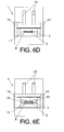
- Figures 6A-6E show a process similar to the process of Figures 5A-5E , but with the difference that the reinforcing member 7 is deposited on the lining layer 8 before the thermoplastic material 2 is deposited in the cavity 11 of the mold 1.
- Figures 7A-7F show in greater detail part of a process in which the carrier support comprises the reinforcing member 7, which is held by clamps 15 associated to the manipulator 6.
- Figure 7A shows how the reinforcing member 7 is positioned close to the manipulator 6, and in Figure 7B the manipulator 6 holds the reinforcing member 7 and positions it so that it can receive the thermoplastic material from the dispensing member 5 ( Figures 7B and 7C ).
- the reinforcing member is introduced in the mold 1 ( Figure 7D ) and the manipulator lowers it such that it places it in the cavity 11 of the mold ( Figure 7E ), where it releases it ( Figure 7F ). Drops are thus prevented which could cause the unwanted movement of the thermoplastic material with regard to the reinforcing member 7 and/or with regard to the cavity 11 of the mold.
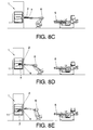
- FIGs 8A-8E show an alternative embodiment in which the reinforcing member 7 is placed on the carrier support 4 ( Figure 8A ) before the thermoplastic material is deposited, such that the thermoplastic material is deposited on the reinforcing member ( Figure 8B ), after which the manipulator 6 moves the carrier support 4 with the reinforcing member 7 towards the mold ( Figure 8C ), positioning it close to the cavity of the mold ( Figure 8D ), after which it pours the thermoplastic material 2, along with the reinforcing member 7, into the cavity of the mold 11.
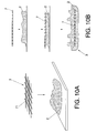
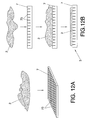
- Figures 10A , 11A and 12A show three different types of reinforcing members 7 (which can also be or form part of the carrier support 4, as explained above).
- Figure 10A shows a reinforcing member 7 in the form of flexible mesh with its through holes 71
- Figure 11A shows a rigid reinforcing member 7 with through holes 72
- Figure 12A shows a reinforcing member 7 having non-through holes or perforations 73.
- the pressure in the molding process makes the thermoplastic material 2 enter the holes 71, 72 and 73, such that the reinforcing member 7 in the obtained product 3 is embedded in the thermoplastic material ( Figures 10B , 11B ) or the thermoplastic material adheres to at least one surface of the reinforcing member ( Figure 12B ), with a suitable degree of coupling due to the fact that the thermoplastic material enters the through holes 71, 72 ( Figures 10B , 11B ) and non-through holes 73 ( Figure 12B ), respectively. Therefore, in all the cases shown, the correct coupling between the thermoplastic material and the reinforcing member is achieved by the penetration of the thermoplastic material in the holes of the reinforcing member.
- the invention relates to a versatile process which aids in the manufacture of products from thermoplastic resins.
- the invention is not limited to the specific embodiments described above, but also comprises, for example, the variants that can be carried out by a person with average skills in the art (for example in relation to the choice of materials, dimensions, components, layout, etc.) within the scope of the following claims.
Landscapes
- Engineering & Computer Science (AREA)
- Mechanical Engineering (AREA)
- Robotics (AREA)
- Casting Or Compression Moulding Of Plastics Or The Like (AREA)
- Moulds For Moulding Plastics Or The Like (AREA)
Priority Applications (2)
| Application Number | Priority Date | Filing Date | Title |
|---|---|---|---|
| US12/175,406 US9186826B2 (en) | 2007-07-18 | 2008-07-17 | Process for obtaining a thermoplastic material product, and the corresponding product |
| CN200810132120.1A CN101352907B (zh) | 2007-07-18 | 2008-07-18 | 获取热塑性材料产品的方法及其相应的产品 |
Applications Claiming Priority (1)
| Application Number | Priority Date | Filing Date | Title |
|---|---|---|---|
| ES200701999A ES2344039B1 (es) | 2007-07-18 | 2007-07-18 | Procedimiento para la obtencion de un producto de material termoplastico, y el producto correspondiente. |
Publications (2)
| Publication Number | Publication Date |
|---|---|
| EP2018952A1 true EP2018952A1 (de) | 2009-01-28 |
| EP2018952B1 EP2018952B1 (de) | 2013-06-26 |
Family
ID=39877947
Family Applications (1)
| Application Number | Title | Priority Date | Filing Date |
|---|---|---|---|
| EP07380399.1A Not-in-force EP2018952B1 (de) | 2007-07-18 | 2007-12-28 | Verfahren zur Gewinnung eines Kunststoffteiles aus thermoplastischen Material |
Country Status (4)
| Country | Link |
|---|---|
| US (1) | US9186826B2 (de) |
| EP (1) | EP2018952B1 (de) |
| CN (1) | CN101352907B (de) |
| ES (2) | ES2344039B1 (de) |
Cited By (1)
| Publication number | Priority date | Publication date | Assignee | Title |
|---|---|---|---|---|
| FR2957837A1 (fr) * | 2010-03-26 | 2011-09-30 | Philippe Kuntz | Module flexible |
Families Citing this family (2)
| Publication number | Priority date | Publication date | Assignee | Title |
|---|---|---|---|---|
| CN116141560A (zh) * | 2023-01-31 | 2023-05-23 | 苏州中集良才物流科技股份有限公司 | 一种厚重托盘压塑成型工艺方法 |
| BE1032683B1 (nl) * | 2024-06-11 | 2026-01-20 | Indupack | Kunststofrijplaatproductiesysteem |
Citations (16)
| Publication number | Priority date | Publication date | Assignee | Title |
|---|---|---|---|---|
| JPS5678953A (en) | 1979-11-30 | 1981-06-29 | Matsushita Electric Works Ltd | Preparation of building panel |
| US4571320A (en) * | 1984-10-31 | 1986-02-18 | General Motors Corporation | Method and apparatus for loading and unloading sheet molding compound in and from a press |
| DE3642063A1 (de) | 1985-12-19 | 1987-07-02 | Braas & Co Gmbh | Plastisch verformbares abdeckmaterial |
| US4971544A (en) * | 1986-11-19 | 1990-11-20 | Bucher-Guyer Ag | Apparatus for charging a mold to produce molded plastic parts |
| JPH039836A (ja) | 1989-06-07 | 1991-01-17 | Nishikawa Rubber Co Ltd | プラスチツク製品及びその製造方法 |
| US5135694A (en) | 1989-11-10 | 1992-08-04 | Seiko Epson Corporation | Electronic device wristband |
| WO1995001248A1 (en) * | 1993-07-02 | 1995-01-12 | Giorgio Ravera | Method for depositing two superposed layers of thermoplastics material on a die |
| DE19922202A1 (de) | 1999-05-12 | 2000-11-23 | Albrecht Kloeckner | Plastisch verformbare Materialbahn |
| US6224363B1 (en) * | 1999-07-15 | 2001-05-01 | Pilot Industries, Inc. | System for loading raw material and unloading finished parts from a compression mold |
| JP2001301074A (ja) | 2000-04-21 | 2001-10-30 | Shigeru Co Ltd | 積層成形品及びその製造方法 |
| US20020035796A1 (en) | 2000-08-02 | 2002-03-28 | Bernhard Knoche | Light running shoe |
| JP2003039580A (ja) | 2001-07-31 | 2003-02-13 | Inoac Corp | 導電性シートおよびその製造方法 |
| DE10253830A1 (de) * | 2002-11-18 | 2004-06-03 | Carcoustics Tech Center Gmbh | Perforierte Folie und Verfahren sowie Vorrichtung zum Perforieren eines flächigen Materials |
| US6852268B1 (en) * | 1997-08-14 | 2005-02-08 | The University Of Massachusetts | Process for preparing a molded article |
| EP1529618A1 (de) | 2003-11-04 | 2005-05-11 | Oniris | Verfahren zur Herstellung eines Bettes |
| JP2006289651A (ja) | 2005-04-06 | 2006-10-26 | Victor Kogyo Kk | 高強度高機能樹脂成形品およびその製造方法 |
Family Cites Families (14)
| Publication number | Priority date | Publication date | Assignee | Title |
|---|---|---|---|---|
| US3758060A (en) * | 1971-10-20 | 1973-09-11 | Fastway Fasteners | Cable clamp or fastener |
| US4411944A (en) * | 1981-06-01 | 1983-10-25 | Chivas Products Limited | Surface mounted trim piece |
| US4541320A (en) * | 1983-01-20 | 1985-09-17 | Sciuto Michael N | Stringed instrument saddle lock |
| US4970044A (en) * | 1988-03-30 | 1990-11-13 | General Electric Company | Compression molding using insulating films |
| US5626382A (en) * | 1995-04-03 | 1997-05-06 | Lear Corporation | Molded plastic panel having integrated, localized soft-touch aesthetic feature |
| JP3009836B2 (ja) | 1995-08-22 | 2000-02-14 | 日立電子株式会社 | 凹面鏡 |
| AUPO724797A0 (en) * | 1997-06-06 | 1997-07-03 | Down Hole Technologies Pty Ltd | Retrieval head for a drill bit composed of a plurality of bit segments |
| US6264462B1 (en) * | 1999-09-01 | 2001-07-24 | Robert M. Gallagher | Polymer transfer and deposition molding device |
| US6497775B2 (en) * | 2001-04-11 | 2002-12-24 | Delphi Technologies, Inc. | Method and apparatus for manufacturing a vehicle cross car beam or other structural, functional articles out of multiple materials with optimum material utilization |
| US6796788B2 (en) * | 2001-05-30 | 2004-09-28 | Robert M. Gallagher | Carrier transfer molding device |
| US7255822B2 (en) * | 2002-01-31 | 2007-08-14 | Owens-Corning Fiberglas Technology Inc. | Process for manufacturing a composite sheet |
| JP2006042411A (ja) * | 2004-07-22 | 2006-02-09 | Disco Abrasive Syst Ltd | 配線固定具 |
| TWI359069B (en) * | 2004-11-02 | 2012-03-01 | Apic Yamada Corp | Resin molding equipment and resin molding method |
| US20060138689A1 (en) * | 2004-12-29 | 2006-06-29 | Endrud John N | Apparatus and method for compression molding a chair mat |
-
2007
- 2007-07-18 ES ES200701999A patent/ES2344039B1/es not_active Expired - Fee Related
- 2007-12-28 EP EP07380399.1A patent/EP2018952B1/de not_active Not-in-force
- 2007-12-28 ES ES07380399T patent/ES2428341T3/es active Active
-
2008
- 2008-07-17 US US12/175,406 patent/US9186826B2/en not_active Expired - Fee Related
- 2008-07-18 CN CN200810132120.1A patent/CN101352907B/zh not_active Expired - Fee Related
Patent Citations (16)
| Publication number | Priority date | Publication date | Assignee | Title |
|---|---|---|---|---|
| JPS5678953A (en) | 1979-11-30 | 1981-06-29 | Matsushita Electric Works Ltd | Preparation of building panel |
| US4571320A (en) * | 1984-10-31 | 1986-02-18 | General Motors Corporation | Method and apparatus for loading and unloading sheet molding compound in and from a press |
| DE3642063A1 (de) | 1985-12-19 | 1987-07-02 | Braas & Co Gmbh | Plastisch verformbares abdeckmaterial |
| US4971544A (en) * | 1986-11-19 | 1990-11-20 | Bucher-Guyer Ag | Apparatus for charging a mold to produce molded plastic parts |
| JPH039836A (ja) | 1989-06-07 | 1991-01-17 | Nishikawa Rubber Co Ltd | プラスチツク製品及びその製造方法 |
| US5135694A (en) | 1989-11-10 | 1992-08-04 | Seiko Epson Corporation | Electronic device wristband |
| WO1995001248A1 (en) * | 1993-07-02 | 1995-01-12 | Giorgio Ravera | Method for depositing two superposed layers of thermoplastics material on a die |
| US6852268B1 (en) * | 1997-08-14 | 2005-02-08 | The University Of Massachusetts | Process for preparing a molded article |
| DE19922202A1 (de) | 1999-05-12 | 2000-11-23 | Albrecht Kloeckner | Plastisch verformbare Materialbahn |
| US6224363B1 (en) * | 1999-07-15 | 2001-05-01 | Pilot Industries, Inc. | System for loading raw material and unloading finished parts from a compression mold |
| JP2001301074A (ja) | 2000-04-21 | 2001-10-30 | Shigeru Co Ltd | 積層成形品及びその製造方法 |
| US20020035796A1 (en) | 2000-08-02 | 2002-03-28 | Bernhard Knoche | Light running shoe |
| JP2003039580A (ja) | 2001-07-31 | 2003-02-13 | Inoac Corp | 導電性シートおよびその製造方法 |
| DE10253830A1 (de) * | 2002-11-18 | 2004-06-03 | Carcoustics Tech Center Gmbh | Perforierte Folie und Verfahren sowie Vorrichtung zum Perforieren eines flächigen Materials |
| EP1529618A1 (de) | 2003-11-04 | 2005-05-11 | Oniris | Verfahren zur Herstellung eines Bettes |
| JP2006289651A (ja) | 2005-04-06 | 2006-10-26 | Victor Kogyo Kk | 高強度高機能樹脂成形品およびその製造方法 |
Cited By (1)
| Publication number | Priority date | Publication date | Assignee | Title |
|---|---|---|---|---|
| FR2957837A1 (fr) * | 2010-03-26 | 2011-09-30 | Philippe Kuntz | Module flexible |
Also Published As
| Publication number | Publication date |
|---|---|
| CN101352907B (zh) | 2014-10-15 |
| ES2344039A1 (es) | 2010-08-16 |
| ES2344039B1 (es) | 2011-08-18 |
| US9186826B2 (en) | 2015-11-17 |
| US20090072440A1 (en) | 2009-03-19 |
| EP2018952B1 (de) | 2013-06-26 |
| ES2428341T3 (es) | 2013-11-07 |
| CN101352907A (zh) | 2009-01-28 |
Similar Documents
| Publication | Publication Date | Title |
|---|---|---|
| EP0480153B1 (de) | Verfahren und Vorrichtung zum Herstellen eines Kunststofformteils | |
| EP3310545B1 (de) | Verfahren zum herstellen eines kunststoffformkörpers, kunststoffformkörper und formwerkzeug | |
| DE69833439T2 (de) | Verfahren und gerät zum herstellen eines geformten gegenstandes | |
| EP1115547B1 (de) | Verfahren zum herstellen von beschichteten kunststoffformteilen | |
| US20020109263A1 (en) | Process for preparing composite molded articles by multicomponent injection molding | |
| US11097454B2 (en) | Hybrid part manufacturing system and method | |
| EP0043174A2 (de) | Verfahren zum Spritzgiessen von Kunststoffen | |
| EP0495219A2 (de) | Verfahren und Vorrichtung zum Herstellen laminierter Formteile | |
| US9186826B2 (en) | Process for obtaining a thermoplastic material product, and the corresponding product | |
| EP0692362B1 (de) | Verfahren zur Herstellung eines thermoplastischen Kunststoffgegenstandes und Formzusammenbau dafür | |
| KR19990036152A (ko) | 여러개의 영역을 가진 플라스틱 몰딩 및 이를 생산하기 위한 장치와 방법 | |
| CN104512001A (zh) | 树脂成形体的制造方法 | |
| EP0543085A1 (de) | Verfahren und Vorrichtung zum Herstellen laminierter Formteile | |
| US6183680B1 (en) | Process for producing multilayer molded article | |
| DE19740468C1 (de) | Verfahren und Vorrichtung zum Hinterspritzen von flächigem Material | |
| DE20120819U1 (de) | Abdeckteil mit Klappe auf Basis faserverstärkter Kunststoffe | |
| US20160361850A1 (en) | Molded member and method of manufacturing the same | |
| US20070210484A1 (en) | Process for making a multilayer part with a flexible local zone designed, for example, to be used as interior fittings for a motor vehicle | |
| PT914238E (pt) | Processo e dispositivo para a producao de elementos moveis de um componente de plastico bem como tais elementos moveis | |
| JP3377547B2 (ja) | 多層射出プレス成形装置 | |
| US20030038402A1 (en) | Method and apparatus for producing a multipurpose panel with structural, functional, and energy absorbing features | |
| JP3314979B2 (ja) | スタンピング成形用型およびスタンピング成形方法 | |
| EP1468806B1 (de) | Verfahren zum erhalt von mit flansch versehenen beschichteten kunststoffteilen | |
| KR20080077141A (ko) | 다층 사출성형장치 및 상기 다층 사출성형장치를 사용한적층수지 성형품의 성형방법 | |
| AT724U1 (de) | Düse mit einer düsenöffnung zum einbringen von geschmolzenem kunststoff |
Legal Events
| Date | Code | Title | Description |
|---|---|---|---|
| PUAI | Public reference made under article 153(3) epc to a published international application that has entered the european phase |
Free format text: ORIGINAL CODE: 0009012 |
|
| AK | Designated contracting states |
Kind code of ref document: A1 Designated state(s): AT BE BG CH CY CZ DE DK EE ES FI FR GB GR HU IE IS IT LI LT LU LV MC MT NL PL PT RO SE SI SK TR |
|
| AX | Request for extension of the european patent |
Extension state: AL BA HR MK RS |
|
| 17P | Request for examination filed |
Effective date: 20090727 |
|
| 17Q | First examination report despatched |
Effective date: 20090819 |
|
| AKX | Designation fees paid |
Designated state(s): AT BE BG CH CY CZ DE DK EE ES FI FR GB GR HU IE IS IT LI LT LU LV MC MT NL PL PT RO SE SI SK TR |
|
| GRAP | Despatch of communication of intention to grant a patent |
Free format text: ORIGINAL CODE: EPIDOSNIGR1 |
|
| GRAS | Grant fee paid |
Free format text: ORIGINAL CODE: EPIDOSNIGR3 |
|
| GRAA | (expected) grant |
Free format text: ORIGINAL CODE: 0009210 |
|
| AK | Designated contracting states |
Kind code of ref document: B1 Designated state(s): AT BE BG CH CY CZ DE DK EE ES FI FR GB GR HU IE IS IT LI LT LU LV MC MT NL PL PT RO SE SI SK TR |
|
| REG | Reference to a national code |
Ref country code: GB Ref legal event code: FG4D |
|
| REG | Reference to a national code |
Ref country code: CH Ref legal event code: EP |
|
| REG | Reference to a national code |
Ref country code: AT Ref legal event code: REF Ref document number: 618501 Country of ref document: AT Kind code of ref document: T Effective date: 20130715 |
|
| REG | Reference to a national code |
Ref country code: IE Ref legal event code: FG4D |
|
| REG | Reference to a national code |
Ref country code: DE Ref legal event code: R096 Ref document number: 602007031235 Country of ref document: DE Effective date: 20130814 |
|
| PG25 | Lapsed in a contracting state [announced via postgrant information from national office to epo] |
Ref country code: SI Free format text: LAPSE BECAUSE OF FAILURE TO SUBMIT A TRANSLATION OF THE DESCRIPTION OR TO PAY THE FEE WITHIN THE PRESCRIBED TIME-LIMIT Effective date: 20130626 Ref country code: LT Free format text: LAPSE BECAUSE OF FAILURE TO SUBMIT A TRANSLATION OF THE DESCRIPTION OR TO PAY THE FEE WITHIN THE PRESCRIBED TIME-LIMIT Effective date: 20130626 Ref country code: GR Free format text: LAPSE BECAUSE OF FAILURE TO SUBMIT A TRANSLATION OF THE DESCRIPTION OR TO PAY THE FEE WITHIN THE PRESCRIBED TIME-LIMIT Effective date: 20130927 Ref country code: FI Free format text: LAPSE BECAUSE OF FAILURE TO SUBMIT A TRANSLATION OF THE DESCRIPTION OR TO PAY THE FEE WITHIN THE PRESCRIBED TIME-LIMIT Effective date: 20130626 Ref country code: SE Free format text: LAPSE BECAUSE OF FAILURE TO SUBMIT A TRANSLATION OF THE DESCRIPTION OR TO PAY THE FEE WITHIN THE PRESCRIBED TIME-LIMIT Effective date: 20130626 |
|
| REG | Reference to a national code |
Ref country code: ES Ref legal event code: FG2A Ref document number: 2428341 Country of ref document: ES Kind code of ref document: T3 Effective date: 20131107 |
|
| REG | Reference to a national code |
Ref country code: AT Ref legal event code: MK05 Ref document number: 618501 Country of ref document: AT Kind code of ref document: T Effective date: 20130626 |
|
| REG | Reference to a national code |
Ref country code: LT Ref legal event code: MG4D |
|
| PG25 | Lapsed in a contracting state [announced via postgrant information from national office to epo] |
Ref country code: BG Free format text: LAPSE BECAUSE OF FAILURE TO SUBMIT A TRANSLATION OF THE DESCRIPTION OR TO PAY THE FEE WITHIN THE PRESCRIBED TIME-LIMIT Effective date: 20130926 |
|
| REG | Reference to a national code |
Ref country code: NL Ref legal event code: VDEP Effective date: 20130626 |
|
| PG25 | Lapsed in a contracting state [announced via postgrant information from national office to epo] |
Ref country code: LV Free format text: LAPSE BECAUSE OF FAILURE TO SUBMIT A TRANSLATION OF THE DESCRIPTION OR TO PAY THE FEE WITHIN THE PRESCRIBED TIME-LIMIT Effective date: 20130626 |
|
| PG25 | Lapsed in a contracting state [announced via postgrant information from national office to epo] |
Ref country code: IS Free format text: LAPSE BECAUSE OF FAILURE TO SUBMIT A TRANSLATION OF THE DESCRIPTION OR TO PAY THE FEE WITHIN THE PRESCRIBED TIME-LIMIT Effective date: 20131026 Ref country code: PT Free format text: LAPSE BECAUSE OF FAILURE TO SUBMIT A TRANSLATION OF THE DESCRIPTION OR TO PAY THE FEE WITHIN THE PRESCRIBED TIME-LIMIT Effective date: 20131028 Ref country code: BE Free format text: LAPSE BECAUSE OF FAILURE TO SUBMIT A TRANSLATION OF THE DESCRIPTION OR TO PAY THE FEE WITHIN THE PRESCRIBED TIME-LIMIT Effective date: 20130626 Ref country code: AT Free format text: LAPSE BECAUSE OF FAILURE TO SUBMIT A TRANSLATION OF THE DESCRIPTION OR TO PAY THE FEE WITHIN THE PRESCRIBED TIME-LIMIT Effective date: 20130626 Ref country code: EE Free format text: LAPSE BECAUSE OF FAILURE TO SUBMIT A TRANSLATION OF THE DESCRIPTION OR TO PAY THE FEE WITHIN THE PRESCRIBED TIME-LIMIT Effective date: 20130626 Ref country code: SK Free format text: LAPSE BECAUSE OF FAILURE TO SUBMIT A TRANSLATION OF THE DESCRIPTION OR TO PAY THE FEE WITHIN THE PRESCRIBED TIME-LIMIT Effective date: 20130626 Ref country code: CY Free format text: LAPSE BECAUSE OF FAILURE TO SUBMIT A TRANSLATION OF THE DESCRIPTION OR TO PAY THE FEE WITHIN THE PRESCRIBED TIME-LIMIT Effective date: 20130724 |
|
| PG25 | Lapsed in a contracting state [announced via postgrant information from national office to epo] |
Ref country code: NL Free format text: LAPSE BECAUSE OF FAILURE TO SUBMIT A TRANSLATION OF THE DESCRIPTION OR TO PAY THE FEE WITHIN THE PRESCRIBED TIME-LIMIT Effective date: 20130626 Ref country code: PL Free format text: LAPSE BECAUSE OF FAILURE TO SUBMIT A TRANSLATION OF THE DESCRIPTION OR TO PAY THE FEE WITHIN THE PRESCRIBED TIME-LIMIT Effective date: 20130626 Ref country code: RO Free format text: LAPSE BECAUSE OF FAILURE TO SUBMIT A TRANSLATION OF THE DESCRIPTION OR TO PAY THE FEE WITHIN THE PRESCRIBED TIME-LIMIT Effective date: 20130626 |
|
| PG25 | Lapsed in a contracting state [announced via postgrant information from national office to epo] |
Ref country code: CY Free format text: LAPSE BECAUSE OF FAILURE TO SUBMIT A TRANSLATION OF THE DESCRIPTION OR TO PAY THE FEE WITHIN THE PRESCRIBED TIME-LIMIT Effective date: 20130626 |
|
| PG25 | Lapsed in a contracting state [announced via postgrant information from national office to epo] |
Ref country code: DK Free format text: LAPSE BECAUSE OF FAILURE TO SUBMIT A TRANSLATION OF THE DESCRIPTION OR TO PAY THE FEE WITHIN THE PRESCRIBED TIME-LIMIT Effective date: 20130626 |
|
| PLBE | No opposition filed within time limit |
Free format text: ORIGINAL CODE: 0009261 |
|
| STAA | Information on the status of an ep patent application or granted ep patent |
Free format text: STATUS: NO OPPOSITION FILED WITHIN TIME LIMIT |
|
| PG25 | Lapsed in a contracting state [announced via postgrant information from national office to epo] |
Ref country code: IT Free format text: LAPSE BECAUSE OF FAILURE TO SUBMIT A TRANSLATION OF THE DESCRIPTION OR TO PAY THE FEE WITHIN THE PRESCRIBED TIME-LIMIT Effective date: 20130626 |
|
| 26N | No opposition filed |
Effective date: 20140327 |
|
| REG | Reference to a national code |
Ref country code: DE Ref legal event code: R097 Ref document number: 602007031235 Country of ref document: DE Effective date: 20140327 |
|
| REG | Reference to a national code |
Ref country code: CH Ref legal event code: PL |
|
| GBPC | Gb: european patent ceased through non-payment of renewal fee |
Effective date: 20131228 |
|
| PG25 | Lapsed in a contracting state [announced via postgrant information from national office to epo] |
Ref country code: LU Free format text: LAPSE BECAUSE OF FAILURE TO SUBMIT A TRANSLATION OF THE DESCRIPTION OR TO PAY THE FEE WITHIN THE PRESCRIBED TIME-LIMIT Effective date: 20131228 Ref country code: MC Free format text: LAPSE BECAUSE OF FAILURE TO SUBMIT A TRANSLATION OF THE DESCRIPTION OR TO PAY THE FEE WITHIN THE PRESCRIBED TIME-LIMIT Effective date: 20130626 |
|
| REG | Reference to a national code |
Ref country code: IE Ref legal event code: MM4A |
|
| PG25 | Lapsed in a contracting state [announced via postgrant information from national office to epo] |
Ref country code: LI Free format text: LAPSE BECAUSE OF NON-PAYMENT OF DUE FEES Effective date: 20131231 Ref country code: CH Free format text: LAPSE BECAUSE OF NON-PAYMENT OF DUE FEES Effective date: 20131231 Ref country code: IE Free format text: LAPSE BECAUSE OF NON-PAYMENT OF DUE FEES Effective date: 20131228 |
|
| PG25 | Lapsed in a contracting state [announced via postgrant information from national office to epo] |
Ref country code: GB Free format text: LAPSE BECAUSE OF NON-PAYMENT OF DUE FEES Effective date: 20131228 |
|
| PG25 | Lapsed in a contracting state [announced via postgrant information from national office to epo] |
Ref country code: TR Free format text: LAPSE BECAUSE OF FAILURE TO SUBMIT A TRANSLATION OF THE DESCRIPTION OR TO PAY THE FEE WITHIN THE PRESCRIBED TIME-LIMIT Effective date: 20130626 |
|
| PG25 | Lapsed in a contracting state [announced via postgrant information from national office to epo] |
Ref country code: HU Free format text: LAPSE BECAUSE OF FAILURE TO SUBMIT A TRANSLATION OF THE DESCRIPTION OR TO PAY THE FEE WITHIN THE PRESCRIBED TIME-LIMIT; INVALID AB INITIO Effective date: 20071228 |
|
| PG25 | Lapsed in a contracting state [announced via postgrant information from national office to epo] |
Ref country code: MT Free format text: LAPSE BECAUSE OF FAILURE TO SUBMIT A TRANSLATION OF THE DESCRIPTION OR TO PAY THE FEE WITHIN THE PRESCRIBED TIME-LIMIT Effective date: 20130626 |
|
| REG | Reference to a national code |
Ref country code: FR Ref legal event code: PLFP Year of fee payment: 9 |
|
| REG | Reference to a national code |
Ref country code: FR Ref legal event code: PLFP Year of fee payment: 10 |
|
| REG | Reference to a national code |
Ref country code: FR Ref legal event code: PLFP Year of fee payment: 11 |
|
| PGFP | Annual fee paid to national office [announced via postgrant information from national office to epo] |
Ref country code: FR Payment date: 20201111 Year of fee payment: 14 |
|
| PGFP | Annual fee paid to national office [announced via postgrant information from national office to epo] |
Ref country code: DE Payment date: 20201229 Year of fee payment: 14 |
|
| PGFP | Annual fee paid to national office [announced via postgrant information from national office to epo] |
Ref country code: CZ Payment date: 20211221 Year of fee payment: 15 |
|
| PGFP | Annual fee paid to national office [announced via postgrant information from national office to epo] |
Ref country code: ES Payment date: 20220103 Year of fee payment: 15 |
|
| REG | Reference to a national code |
Ref country code: DE Ref legal event code: R119 Ref document number: 602007031235 Country of ref document: DE |
|
| PG25 | Lapsed in a contracting state [announced via postgrant information from national office to epo] |
Ref country code: DE Free format text: LAPSE BECAUSE OF NON-PAYMENT OF DUE FEES Effective date: 20220701 |
|
| PG25 | Lapsed in a contracting state [announced via postgrant information from national office to epo] |
Ref country code: FR Free format text: LAPSE BECAUSE OF NON-PAYMENT OF DUE FEES Effective date: 20211231 |
|
| PG25 | Lapsed in a contracting state [announced via postgrant information from national office to epo] |
Ref country code: CZ Free format text: LAPSE BECAUSE OF NON-PAYMENT OF DUE FEES Effective date: 20221228 |
|
| REG | Reference to a national code |
Ref country code: ES Ref legal event code: FD2A Effective date: 20240202 |
|
| PG25 | Lapsed in a contracting state [announced via postgrant information from national office to epo] |
Ref country code: ES Free format text: LAPSE BECAUSE OF NON-PAYMENT OF DUE FEES Effective date: 20221229 |
|
| PG25 | Lapsed in a contracting state [announced via postgrant information from national office to epo] |
Ref country code: ES Free format text: LAPSE BECAUSE OF NON-PAYMENT OF DUE FEES Effective date: 20221229 |