EP2018983A2 - Système de suspension pour un véhicule automobile et procédé destiné à la régulation de la dynamique de véhicule - Google Patents
Système de suspension pour un véhicule automobile et procédé destiné à la régulation de la dynamique de véhicule Download PDFInfo
- Publication number
- EP2018983A2 EP2018983A2 EP08009787A EP08009787A EP2018983A2 EP 2018983 A2 EP2018983 A2 EP 2018983A2 EP 08009787 A EP08009787 A EP 08009787A EP 08009787 A EP08009787 A EP 08009787A EP 2018983 A2 EP2018983 A2 EP 2018983A2
- Authority
- EP
- European Patent Office
- Prior art keywords
- hydraulic
- vehicle
- camber adjustment
- roll stabilization
- suspension system
- Prior art date
- Legal status (The legal status is an assumption and is not a legal conclusion. Google has not performed a legal analysis and makes no representation as to the accuracy of the status listed.)
- Granted
Links
Images
Classifications
-
- B—PERFORMING OPERATIONS; TRANSPORTING
- B62—LAND VEHICLES FOR TRAVELLING OTHERWISE THAN ON RAILS
- B62D—MOTOR VEHICLES; TRAILERS
- B62D17/00—Means on vehicles for adjusting camber, castor, or toe-in
-
- B—PERFORMING OPERATIONS; TRANSPORTING
- B60—VEHICLES IN GENERAL
- B60G—VEHICLE SUSPENSION ARRANGEMENTS
- B60G17/00—Resilient suspensions having means for adjusting the spring or vibration-damper characteristics, for regulating the distance between a supporting surface and a sprung part of vehicle or for locking suspension during use to meet varying vehicular or surface conditions, e.g. due to speed or load
- B60G17/015—Resilient suspensions having means for adjusting the spring or vibration-damper characteristics, for regulating the distance between a supporting surface and a sprung part of vehicle or for locking suspension during use to meet varying vehicular or surface conditions, e.g. due to speed or load the regulating means comprising electric or electronic elements
- B60G17/016—Resilient suspensions having means for adjusting the spring or vibration-damper characteristics, for regulating the distance between a supporting surface and a sprung part of vehicle or for locking suspension during use to meet varying vehicular or surface conditions, e.g. due to speed or load the regulating means comprising electric or electronic elements characterised by their responsiveness, when the vehicle is travelling, to specific motion, a specific condition, or driver input
- B60G17/0162—Resilient suspensions having means for adjusting the spring or vibration-damper characteristics, for regulating the distance between a supporting surface and a sprung part of vehicle or for locking suspension during use to meet varying vehicular or surface conditions, e.g. due to speed or load the regulating means comprising electric or electronic elements characterised by their responsiveness, when the vehicle is travelling, to specific motion, a specific condition, or driver input mainly during a motion involving steering operation, e.g. cornering, overtaking
-
- B—PERFORMING OPERATIONS; TRANSPORTING
- B60—VEHICLES IN GENERAL
- B60G—VEHICLE SUSPENSION ARRANGEMENTS
- B60G21/00—Interconnection systems for two or more resiliently-suspended wheels, e.g. for stabilising a vehicle body with respect to acceleration, deceleration or centrifugal forces
- B60G21/02—Interconnection systems for two or more resiliently-suspended wheels, e.g. for stabilising a vehicle body with respect to acceleration, deceleration or centrifugal forces permanently interconnected
- B60G21/04—Interconnection systems for two or more resiliently-suspended wheels, e.g. for stabilising a vehicle body with respect to acceleration, deceleration or centrifugal forces permanently interconnected mechanically
- B60G21/05—Interconnection systems for two or more resiliently-suspended wheels, e.g. for stabilising a vehicle body with respect to acceleration, deceleration or centrifugal forces permanently interconnected mechanically between wheels on the same axle but on different sides of the vehicle, i.e. the left and right wheel suspensions being interconnected
- B60G21/055—Stabiliser bars
- B60G21/0551—Mounting means therefor
- B60G21/0553—Mounting means therefor adjustable
- B60G21/0555—Mounting means therefor adjustable including an actuator inducing vehicle roll
-
- B—PERFORMING OPERATIONS; TRANSPORTING
- B60—VEHICLES IN GENERAL
- B60G—VEHICLE SUSPENSION ARRANGEMENTS
- B60G21/00—Interconnection systems for two or more resiliently-suspended wheels, e.g. for stabilising a vehicle body with respect to acceleration, deceleration or centrifugal forces
- B60G21/02—Interconnection systems for two or more resiliently-suspended wheels, e.g. for stabilising a vehicle body with respect to acceleration, deceleration or centrifugal forces permanently interconnected
- B60G21/06—Interconnection systems for two or more resiliently-suspended wheels, e.g. for stabilising a vehicle body with respect to acceleration, deceleration or centrifugal forces permanently interconnected fluid
- B60G21/073—Interconnection systems for two or more resiliently-suspended wheels, e.g. for stabilising a vehicle body with respect to acceleration, deceleration or centrifugal forces permanently interconnected fluid between wheels on the same axle but on different sides of the vehicle, i.e. the left and right wheel suspensions being interconnected
-
- B—PERFORMING OPERATIONS; TRANSPORTING
- B60—VEHICLES IN GENERAL
- B60G—VEHICLE SUSPENSION ARRANGEMENTS
- B60G7/00—Pivoted suspension arms; Accessories thereof
- B60G7/006—Attaching arms to sprung or unsprung part of vehicle, characterised by comprising attachment means controlled by an external actuator, e.g. a fluid or electrical motor
-
- B—PERFORMING OPERATIONS; TRANSPORTING
- B60—VEHICLES IN GENERAL
- B60G—VEHICLE SUSPENSION ARRANGEMENTS
- B60G2200/00—Indexing codes relating to suspension types
- B60G2200/40—Indexing codes relating to the wheels in the suspensions
- B60G2200/46—Indexing codes relating to the wheels in the suspensions camber angle
-
- B—PERFORMING OPERATIONS; TRANSPORTING
- B60—VEHICLES IN GENERAL
- B60G—VEHICLE SUSPENSION ARRANGEMENTS
- B60G2202/00—Indexing codes relating to the type of spring, damper or actuator
- B60G2202/40—Type of actuator
- B60G2202/41—Fluid actuator
- B60G2202/413—Hydraulic actuator
-
- B—PERFORMING OPERATIONS; TRANSPORTING
- B60—VEHICLES IN GENERAL
- B60G—VEHICLE SUSPENSION ARRANGEMENTS
- B60G2204/00—Indexing codes related to suspensions per se or to auxiliary parts
- B60G2204/80—Interactive suspensions; arrangement affecting more than one suspension unit
- B60G2204/83—Type of interconnection
- B60G2204/8304—Type of interconnection using a fluid
-
- B—PERFORMING OPERATIONS; TRANSPORTING
- B60—VEHICLES IN GENERAL
- B60G—VEHICLE SUSPENSION ARRANGEMENTS
- B60G2206/00—Indexing codes related to the manufacturing of suspensions: constructional features, the materials used, procedures or tools
- B60G2206/01—Constructional features of suspension elements, e.g. arms, dampers, springs
- B60G2206/10—Constructional features of arms
- B60G2206/11—Constructional features of arms the arm being a radius or track or torque or steering rod or stabiliser end link
- B60G2206/111—Constructional features of arms the arm being a radius or track or torque or steering rod or stabiliser end link of adjustable length
- B60G2206/1116—Actively adjustable during driving
-
- B—PERFORMING OPERATIONS; TRANSPORTING
- B60—VEHICLES IN GENERAL
- B60G—VEHICLE SUSPENSION ARRANGEMENTS
- B60G2800/00—Indexing codes relating to the type of movement or to the condition of the vehicle and to the end result to be achieved by the control action
- B60G2800/01—Attitude or posture control
- B60G2800/012—Rolling condition
- B60G2800/0122—Roll rigidity ratio; Warping
Definitions
- the invention relates to a suspension system for a motor vehicle with a device for roll stabilization and with a device for camber adjustment.
- the invention also relates to a method for driving dynamics control of a motor vehicle using a corresponding suspension system.
- a device for adjusting the camber of a vehicle axle of a motor vehicle wherein at least two provided for articulation of the wheels suspension arms are provided, which acts on an actuator to change the position of the suspension arm, a longitudinally displaceable actuator axis of the actuator on the one hand on the one control arm and on the other engages the other suspension link, wherein the actuator in addition to the actuator axis comprises an electric motor and a ball screw.
- the DE 10 2004 014 576 A1 proposes a method for driving stability control of a vehicle, in which, depending on a driving condition, a rear camber angle of the wheels of the rear axle is actively set, and at the front axle a front anti-roll moment and at the rear axle a rear anti-roll torque are exerted, one of the ratio of the rear Anti-roll torque to the front Antiwankmoment reflecting rolling moment distribution is adjusted in dependence on the rear camber angle of the wheels of the rear axle.
- Object of the present invention is to provide a suspension system and a method for driving dynamics control of a motor vehicle, which improve the driving dynamics and which can be realized in a compact design.
- the device for roll stabilization and the device for Radsatzver one or more hydraulic actuators, wherein the device for roll stabilization and the device for camber adjustment are coupled together by means of a common hydraulic system.
- Roll stabilization and camber adjustment are integrated with each other in the suspension system according to the invention. This greatly simplifies the control, requires relatively few valve components, and provides a highly effective integrated system.
- the device for roll stabilization may have at least one hydraulic adjusting device coupled to a stabilizer.
- the hydraulic adjusting device can be designed as a swivel actuating device for the stabilizer.
- the device for camber adjustment per wheel have a designed as a linear actuator hydraulic cylinder.
- the common hydraulic system may comprise a pressure supply device which is connected via lines to the one or more hydraulic actuators of the roll stabilization device and the camber adjustment device, wherein at least one valve device is provided between the pressure supply device and the hydraulic actuators.
- the pressure supply device may be configured such that the target pressure in the hydraulic system is set depending on vehicle conditions, wherein at least one of the following signals is used to determine a vehicle state: lateral acceleration, steering wheel angle, vehicle speed, roll angle.
- the camber adjustment device i. be provided in particular for the hydraulic adjusting devices, at least one device for adjusting the hydraulic pressure and / or the hydraulic flow.
- the suspension system can be designed for one or more vehicle axles.
- the object underlying the invention is also achieved by a method for driving dynamics control of a motor vehicle using a suspension system according to the invention or one of its developments for active roll stabilization and active camber adjustment in response to a vehicle condition of the motor vehicle.
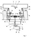
- Fig. 1 shows a schematic diagram of a vehicle body 1 and a suspension system, exemplified in conjunction with an axle of a motor vehicle.
- Two wheels 5a, 5b are assigned to a common axle of the motor vehicle and each have a wheel suspension 16a, 16b.
- a stabilizer 6 preferably a curve stabilizer disposed.
- the Stabilizer 6 may be coupled to the vehicle body 1 by stabilizer bearings 14a, 14b.
- a hydraulic actuator 4 is arranged, which is formed in the example shown as a pivoting actuator, for example as a rotation plate for the stabilizer 6.
- the hydraulic adjusting device 4 may for example also be designed as a linear actuator.
- a hydraulic adjusting device 3a, 3b is provided in the example shown per wheel 5a, 5b.
- the hydraulic adjusting devices 3a, 3b are designed for camber adjustment as linear adjusting devices in the form of hydraulic cylinders. It is also possible, as hydraulic adjusting devices 3a, 3b to provide swivel actuators, which is not shown in detail in the drawing.
- the pivoting actuators are preferably coupled in each case via a lever to the tie rod.
- a vehicle condition is indicated, in which the motor vehicle is in a cornering, wherein the arrow 2 indicates the direction to the center of the curve. Accordingly, due to the cornering, a rolling movement indicated by the arrow 12 occurs.
- the wheels 5a, 5b and the tires have a camber angle 11a, 11b.
- the illustrated hydraulic adjusting devices 4 and 3a, 3b of both the device for roll stabilization and the device for camber adjustment have a common hydraulic system.
- the necessary hydraulic flow is provided by a pressure supply device 10, wherein the hydraulic flow and / or the hydraulic pressure, preferably in response to the acting shear forces, controlled and / or regulated.
- the pressure supply device 10 is coupled via lines 7, 9 with the hydraulic actuators 3a, 3b, 4.
- the line 7 of the hydraulic system is the inflow line.
- the return line is according to this example, the line 9. Accordingly, the hydraulic flow with the arrows 70, 90, 91 indicated for the vehicle state corresponding to the example shown.
- the hydraulic system shown has a tank 15 for hydraulic fluid.
- At least one valve device 8 is provided which, for example, can have a directional valve, with the aid of which the pressurization of the correct piston surfaces can correspond to the respective curve direction or change thereof.
- the vehicle body 1 would, without roll stabilization when cornering, undergo a rolling movement in the direction of the arrow 12, i. make an incline, turn outside.
- the hydraulic adjusting device 4 for roll stabilization effects a torsional moment in the stabilizer 6, which stabilizes the vehicle body 1 by supporting forces in the stabilizer bearings 14a, 14b.
- the active camber adjustment tends the tires or wheels 5a, 5b against the direction of the lateral force in the curve. This is done with the aid of the adjusting devices 3a, 3b.
- the actuators 3a, 3b are coupled together and connected to the hydraulic supply and discharge lines of roll stabilization.
- at least one device 13a, 13b for adjusting the hydraulic pressure and / or the hydraulic flow may be provided for the camber adjustment.
- Such a fitting hydraulic can be used depending on the dimensions of the adjusting devices 3a, 3b for camber adjustment to reduce the pressure or flow. It may be expedient to measure the fall and / or to determine it by calculation.
- the camber adjustment or the adjustment of the hydraulic pressure and / or the hydraulic flow for camber adjustment can be carried out in dependence of the measured and / or determined camber.
- the active camber adjustment causes by an inclination of the tire about its longitudinal axis an optimization of the tire contact patch.
- the deformation of the tire footprint under the influence of the lateral force is counteracted by inclining the tire into the curve.
- the tire can thereby transmit greater lateral forces.
- the energy for camber adjustment is provided by the same hydraulic supply, which also provides energy for roll stabilization.
- the roll stabilization serves to minimize the roll angle when cornering, wherein the hydraulic supply in conjunction with valves and at least one adjusting device '4 on the stabilizer 6 depending on vehicle conditions, e.g. a measured and / or calculated lateral acceleration, a stabilizing force causes the structure.
- the power supply of both the active roll stabilization and the active camber adjustment is hydraulic, wherein the target pressure is determined based on vehicle conditions.
- a vehicle state may be determined by one or more of the following measured and / or calculated quantities: lateral acceleration, steering wheel angle, vehicle speed, roll angle.
- the pressure setting may e.g. with the aid of sensors for example for lateral acceleration, steering wheel angle, vehicle speed, pressure, hydraulic flow and / or path (s) or position (s) of the adjusting devices.
- An essential idea for the invention is the combination of a roll stabilization with a fall adjustment in motor vehicles.
- An active camber adjustment is realized using the hydraulic power supply and the roll stabilization valves.
- the hydraulic flow supplies both the roll stabilization actuators and the camber adjustment actuators.
- the invention and related teaching may be used with a different number of actuators 3a, 3b, 4, with a different number of valve devices, and with a different number of pressure supply devices 10. *** "
Landscapes
- Engineering & Computer Science (AREA)
- Mechanical Engineering (AREA)
- Chemical & Material Sciences (AREA)
- Combustion & Propulsion (AREA)
- Transportation (AREA)
- Vehicle Body Suspensions (AREA)
Applications Claiming Priority (1)
| Application Number | Priority Date | Filing Date | Title |
|---|---|---|---|
| DE102007034840A DE102007034840A1 (de) | 2007-07-26 | 2007-07-26 | Fahrwerkssystem für ein Kraftfahrzeug und Verfahren zur Fahrdynamikregelung |
Publications (3)
| Publication Number | Publication Date |
|---|---|
| EP2018983A2 true EP2018983A2 (fr) | 2009-01-28 |
| EP2018983A3 EP2018983A3 (fr) | 2009-07-08 |
| EP2018983B1 EP2018983B1 (fr) | 2011-07-27 |
Family
ID=39874011
Family Applications (1)
| Application Number | Title | Priority Date | Filing Date |
|---|---|---|---|
| EP08009787A Ceased EP2018983B1 (fr) | 2007-07-26 | 2008-05-29 | Système de suspension pour un véhicule automobile et procédé destiné à la régulation de la dynamique de véhicule |
Country Status (5)
| Country | Link |
|---|---|
| US (1) | US7717438B2 (fr) |
| EP (1) | EP2018983B1 (fr) |
| JP (1) | JP5261053B2 (fr) |
| CN (1) | CN101353054B (fr) |
| DE (1) | DE102007034840A1 (fr) |
Cited By (2)
| Publication number | Priority date | Publication date | Assignee | Title |
|---|---|---|---|---|
| DE102011078262A1 (de) | 2011-06-29 | 2013-01-03 | Ford Global Technologies, Llc | Einzelradaufhängung mit selbsttätiger Sturzanpassung |
| CN105313635A (zh) * | 2014-07-03 | 2016-02-10 | Dr.Ing.h.c.F.保时捷股份公司 | 用于调节车辆车桥的侧倾力矩以获得侧倾稳定的方法 |
Families Citing this family (18)
| Publication number | Priority date | Publication date | Assignee | Title |
|---|---|---|---|---|
| TWI354633B (en) * | 2008-08-05 | 2011-12-21 | Univ Nat Taiwan Science Tech | Motor vehicle and tilting mechanism thereof |
| DE102009025227A1 (de) * | 2009-06-17 | 2010-12-30 | Audi Ag | Radaufhängung für die hinteren Räder von Kraftfahrzeugen |
| EP2418108A1 (fr) | 2010-08-12 | 2012-02-15 | Amenduni Gresele, Massimo | Suspension de voiture automobile avec un dispositif pour changer l'angle de carrossage |
| US8485536B1 (en) * | 2011-05-02 | 2013-07-16 | Philip S. Pierce | Automated actuating shock mount for improved vehicle cornering |
| CN103692878B (zh) * | 2013-12-11 | 2016-05-04 | 郑州宇通客车股份有限公司 | 自适应横向稳定装置及使用装置的车辆悬架系统 |
| CA2953068A1 (fr) * | 2014-07-04 | 2016-01-07 | Riccardo Marabese | Dispositif de freinage electronique du systeme d'inclinaison d'un vehicule avec trois roues a inclinaison ou davantage |
| DE102014217246B3 (de) | 2014-08-29 | 2015-12-24 | Ford Global Technologies, Llc | Stabilisierungsanordnung für ein Neigefahrwerk eines Fahrzeugs |
| DE102014217386B4 (de) | 2014-09-01 | 2024-11-14 | Ford Global Technologies, Llc | Verfahren zum Betrieb eines Neigefahrwerks für ein schienenungebundenes Fahrzeug |
| CN105620221B (zh) * | 2014-11-05 | 2017-10-31 | 长春孔辉汽车科技股份有限公司 | 主动横向稳定杆系统 |
| US10076939B2 (en) | 2014-11-26 | 2018-09-18 | Ford Global Technologies, Llc | Suspension systems for laterally tiltable multitrack vehicles |
| US9925843B2 (en) | 2015-02-24 | 2018-03-27 | Ford Global Technologies, Llc | Rear suspension systems for laterally tiltable multitrack vehicles |
| US10023019B2 (en) * | 2015-02-24 | 2018-07-17 | Ford Global Technologies, Llc | Rear suspension systems with rotary devices for laterally tiltable multitrack vehicles |
| CN106515351B (zh) * | 2016-12-28 | 2023-08-11 | 杨再荣 | 缓冲减震机构、汽车悬挂系统及汽车 |
| CN106904057A (zh) * | 2017-04-12 | 2017-06-30 | 管中林 | 一种具有稳定互联悬架的打药机 |
| CN108216367B (zh) * | 2018-01-22 | 2020-02-07 | 宁波工程学院 | 一种汽车转向时用于调节外倾角的装置及其控制方法 |
| CN108706044B (zh) * | 2018-05-29 | 2021-06-08 | 邵子蒙 | 非差速转向车 |
| US11400978B2 (en) * | 2018-06-08 | 2022-08-02 | Mando Corporation | Vehicle control apparatus and vehicle control method |
| WO2020004024A1 (fr) * | 2018-06-25 | 2020-01-02 | 株式会社クボタ | Véhicule de travail |
Citations (4)
| Publication number | Priority date | Publication date | Assignee | Title |
|---|---|---|---|---|
| US4700972A (en) | 1985-06-20 | 1987-10-20 | Young Colin G | Computerized, central hydraulic, electronic variable suspension |
| WO1999054186A1 (fr) | 1998-04-17 | 1999-10-28 | Francesco Falchi | Dispositif automatique de reduction des effets de la force centrifuge sur des vehicules en virage |
| DE102004014576A1 (de) | 2004-03-25 | 2005-10-13 | Zf Friedrichshafen Ag | Verfahren und Fahrwerksanordnung zur Fahrstabilitätsregelung eines Kraftfahrzeuges |
| EP1754649A1 (fr) | 2005-08-11 | 2007-02-21 | Schaeffler KG | Dispositif pour modifier le carrossage ou le pincement des roues du véhicule |
Family Cites Families (18)
| Publication number | Priority date | Publication date | Assignee | Title |
|---|---|---|---|---|
| US4573702A (en) * | 1982-03-23 | 1986-03-04 | Klem Richard H | Anti-pitch suspension |
| JPS62113652A (ja) * | 1985-11-13 | 1987-05-25 | Nissan Motor Co Ltd | 4輪操舵車両 |
| FR2641503B1 (fr) * | 1989-01-09 | 1991-05-03 | Peugeot | Suspension a carrossage variable pour vehicule automobile |
| JP2813002B2 (ja) * | 1989-09-13 | 1998-10-22 | 株式会社ヨロズ | サスペンション |
| DE4020547A1 (de) * | 1990-06-28 | 1992-01-02 | Porsche Ag | Vorrichtung zur aktiven verstellung eines kraftfahrzeugrades |
| JPH09507816A (ja) * | 1995-05-22 | 1997-08-12 | ヒュンダイ モーター カンパニー | 操向可能な車輪用車両懸架システム |
| TW355699B (en) * | 1995-08-21 | 1999-04-11 | Kiectic Ltd | Vehicular suspension systems |
| DE19637159B4 (de) * | 1996-09-12 | 2004-09-23 | Wolfgang Weiss | Radaufhängung mit selbsttätiger Sturzanpassung |
| KR100295845B1 (ko) * | 1997-12-31 | 2001-10-25 | 이계안 | 자동차의 서스펜션 시스템 |
| DE19836440A1 (de) * | 1998-08-12 | 2000-02-24 | Daimler Chrysler Ag | Radaufhängung für Kraftfahrzeuge, insbesondere unabhängige Radaufhängung für Personenkraftwagen |
| DE19857394C2 (de) * | 1998-12-12 | 2000-11-23 | Daimler Chrysler Ag | Regelbares Aufhängungssystem für ein aktives Fahrwerk eines Kraftfahrzeugs |
| SE516990C2 (sv) * | 1998-12-29 | 2002-04-02 | Volvo Car Corp | Arrangemang för hjulupphängning i fordon |
| US6851679B2 (en) * | 2002-05-01 | 2005-02-08 | Meritor Light Vehicle Technology, Llc | Simplifed adaptive suspension |
| JP2004136814A (ja) * | 2002-10-18 | 2004-05-13 | Kayaba Ind Co Ltd | 捩り剛性力制御装置 |
| US7287621B2 (en) * | 2002-12-20 | 2007-10-30 | Honda Motor Co., Ltd. | Vehicular power transmission mechanism |
| WO2005072999A1 (fr) * | 2004-01-28 | 2005-08-11 | Luk Lamellen Und Kupplungsbau Beteiligungs Kg | Dispositif de stabilisation de roulis |
| DE102004008802B4 (de) * | 2004-02-20 | 2008-03-20 | Iav Gmbh Ingenieurgesellschaft Auto Und Verkehr | Radaufhängung für Räder von Kraftfahrzeugen |
| JP4368735B2 (ja) * | 2004-05-06 | 2009-11-18 | カヤバ工業株式会社 | 車両のロール制御装置 |
-
2007
- 2007-07-26 DE DE102007034840A patent/DE102007034840A1/de not_active Withdrawn
-
2008
- 2008-05-29 EP EP08009787A patent/EP2018983B1/fr not_active Ceased
- 2008-07-08 US US12/169,015 patent/US7717438B2/en active Active
- 2008-07-22 JP JP2008188168A patent/JP5261053B2/ja not_active Expired - Fee Related
- 2008-07-24 CN CN200810129941XA patent/CN101353054B/zh not_active Expired - Fee Related
Patent Citations (4)
| Publication number | Priority date | Publication date | Assignee | Title |
|---|---|---|---|---|
| US4700972A (en) | 1985-06-20 | 1987-10-20 | Young Colin G | Computerized, central hydraulic, electronic variable suspension |
| WO1999054186A1 (fr) | 1998-04-17 | 1999-10-28 | Francesco Falchi | Dispositif automatique de reduction des effets de la force centrifuge sur des vehicules en virage |
| DE102004014576A1 (de) | 2004-03-25 | 2005-10-13 | Zf Friedrichshafen Ag | Verfahren und Fahrwerksanordnung zur Fahrstabilitätsregelung eines Kraftfahrzeuges |
| EP1754649A1 (fr) | 2005-08-11 | 2007-02-21 | Schaeffler KG | Dispositif pour modifier le carrossage ou le pincement des roues du véhicule |
Cited By (3)
| Publication number | Priority date | Publication date | Assignee | Title |
|---|---|---|---|---|
| DE102011078262A1 (de) | 2011-06-29 | 2013-01-03 | Ford Global Technologies, Llc | Einzelradaufhängung mit selbsttätiger Sturzanpassung |
| DE102011078262B4 (de) * | 2011-06-29 | 2020-12-10 | Ford Global Technologies, Llc | Einzelradaufhängung mit selbsttätiger Sturzanpassung |
| CN105313635A (zh) * | 2014-07-03 | 2016-02-10 | Dr.Ing.h.c.F.保时捷股份公司 | 用于调节车辆车桥的侧倾力矩以获得侧倾稳定的方法 |
Also Published As
| Publication number | Publication date |
|---|---|
| EP2018983B1 (fr) | 2011-07-27 |
| CN101353054B (zh) | 2011-07-27 |
| US7717438B2 (en) | 2010-05-18 |
| JP5261053B2 (ja) | 2013-08-14 |
| EP2018983A3 (fr) | 2009-07-08 |
| JP2009029410A (ja) | 2009-02-12 |
| DE102007034840A1 (de) | 2009-01-29 |
| CN101353054A (zh) | 2009-01-28 |
| US20090026719A1 (en) | 2009-01-29 |
Similar Documents
| Publication | Publication Date | Title |
|---|---|---|
| EP2018983B1 (fr) | Système de suspension pour un véhicule automobile et procédé destiné à la régulation de la dynamique de véhicule | |
| DE69713694T2 (de) | Verfahren zum Verbessern der Stabilität eines Fahrzeuges | |
| DE112018005542B4 (de) | Fahrzeugsteuerungssystem | |
| EP0344493A1 (fr) | Système de suspension active | |
| DE102015110470B4 (de) | Fahrzeug und ein aufhängungssystem für das fahrzeug | |
| EP1184214A2 (fr) | Actionneur pour le contrôle actif du chassis | |
| EP1814747A2 (fr) | Procede de commande et de regulation d'un systeme de chassis actif | |
| DE102004007549B4 (de) | Verfahren zum Betrieb eines aktiven Fahrwerksystems | |
| EP1843906B1 (fr) | Systeme de commande ou de reglage de dynamique de conduite pour vehicule automobile a deux voies et deux essieux | |
| DE10018532A1 (de) | Vorrichtung zur Spureinstellung an einem Fahrzeug | |
| DE102006052698A1 (de) | Verfahren und Vorrichtung zum Stabilisieren eines Kraftfahrzeugs | |
| DE10330895A1 (de) | Ausregelung von Geradeauslaufstörungen eines Kraftfahrzeugs | |
| DE10314251A1 (de) | Fahrwerkregelung | |
| DE102004022167B4 (de) | Verstellbarer Hinterachsenträger an einem Kraftfahrzeug und Verfahren zum Verstellen desselben | |
| WO2017220270A1 (fr) | Dispositif de direction pour un véhicule à moteur | |
| DE19622964A1 (de) | Aktiver Wagenheber | |
| DE102015202208A1 (de) | Verfahren zum Betrieb einer Hinterradlenkung sowie Hinterradlenkung für ein Fahrzeug | |
| DE102006046819B4 (de) | Fahrzeug mit zumindest zwei einer Achse zugeordneten Rädern und Verfahren zum aktiven Einstellen eines Spurwinkels eines Rads eines Fahrzeugs | |
| EP1912810B1 (fr) | Procede de fonctionnement conçu pour un systeme de stabilisation de roulis monoaxial d'un vehicule a deux essieux roulant sur double voie | |
| DE102018204606B4 (de) | Aufhängungssteuersystem | |
| DE102005005724A1 (de) | Vorrichtung und Verfahren zur Horizontalkorrektur eines Fahrzeugaufbaus | |
| DE102007050866B4 (de) | Verfahren zur Fehlerüberwachung bei einem Lenksystem | |
| EP3127791B1 (fr) | Dispositif d'amelioration de la securite de conduite des vehicules articules | |
| EP1712381B1 (fr) | Dispositif et procédé pour le réglage continu de la position d'un essieu tandem | |
| WO2008009448A1 (fr) | Direction assistée hydraulique et procédé de commande de ladite direction assistée |
Legal Events
| Date | Code | Title | Description |
|---|---|---|---|
| PUAI | Public reference made under article 153(3) epc to a published international application that has entered the european phase |
Free format text: ORIGINAL CODE: 0009012 |
|
| AK | Designated contracting states |
Kind code of ref document: A2 Designated state(s): AT BE BG CH CY CZ DE DK EE ES FI FR GB GR HR HU IE IS IT LI LT LU LV MC MT NL NO PL PT RO SE SI SK TR |
|
| AX | Request for extension of the european patent |
Extension state: AL BA MK RS |
|
| PUAL | Search report despatched |
Free format text: ORIGINAL CODE: 0009013 |
|
| AK | Designated contracting states |
Kind code of ref document: A3 Designated state(s): AT BE BG CH CY CZ DE DK EE ES FI FR GB GR HR HU IE IS IT LI LT LU LV MC MT NL NO PL PT RO SE SI SK TR |
|
| AX | Request for extension of the european patent |
Extension state: AL BA MK RS |
|
| 17P | Request for examination filed |
Effective date: 20100108 |
|
| AKX | Designation fees paid |
Designated state(s): DE FR GB IT |
|
| 17Q | First examination report despatched |
Effective date: 20100301 |
|
| RAP1 | Party data changed (applicant data changed or rights of an application transferred) |
Owner name: DR. ING. H.C. F. PORSCHE AG |
|
| GRAP | Despatch of communication of intention to grant a patent |
Free format text: ORIGINAL CODE: EPIDOSNIGR1 |
|
| GRAS | Grant fee paid |
Free format text: ORIGINAL CODE: EPIDOSNIGR3 |
|
| GRAA | (expected) grant |
Free format text: ORIGINAL CODE: 0009210 |
|
| AK | Designated contracting states |
Kind code of ref document: B1 Designated state(s): DE FR GB IT |
|
| REG | Reference to a national code |
Ref country code: GB Ref legal event code: FG4D Free format text: NOT ENGLISH |
|
| REG | Reference to a national code |
Ref country code: DE Ref legal event code: R096 Ref document number: 502008004312 Country of ref document: DE Effective date: 20110922 |
|
| PLBE | No opposition filed within time limit |
Free format text: ORIGINAL CODE: 0009261 |
|
| 26N | No opposition filed |
Effective date: 20120502 |
|
| REG | Reference to a national code |
Ref country code: DE Ref legal event code: R097 Ref document number: 502008004312 Country of ref document: DE Effective date: 20120502 |
|
| REG | Reference to a national code |
Ref country code: FR Ref legal event code: PLFP Year of fee payment: 9 |
|
| REG | Reference to a national code |
Ref country code: FR Ref legal event code: PLFP Year of fee payment: 10 |
|
| REG | Reference to a national code |
Ref country code: FR Ref legal event code: PLFP Year of fee payment: 11 |
|
| PGFP | Annual fee paid to national office [announced via postgrant information from national office to epo] |
Ref country code: IT Payment date: 20190527 Year of fee payment: 12 |
|
| PGFP | Annual fee paid to national office [announced via postgrant information from national office to epo] |
Ref country code: FR Payment date: 20190523 Year of fee payment: 12 |
|
| PGFP | Annual fee paid to national office [announced via postgrant information from national office to epo] |
Ref country code: GB Payment date: 20190521 Year of fee payment: 12 |
|
| GBPC | Gb: european patent ceased through non-payment of renewal fee |
Effective date: 20200529 |
|
| PG25 | Lapsed in a contracting state [announced via postgrant information from national office to epo] |
Ref country code: FR Free format text: LAPSE BECAUSE OF NON-PAYMENT OF DUE FEES Effective date: 20200531 Ref country code: GB Free format text: LAPSE BECAUSE OF NON-PAYMENT OF DUE FEES Effective date: 20200529 |
|
| PG25 | Lapsed in a contracting state [announced via postgrant information from national office to epo] |
Ref country code: IT Free format text: LAPSE BECAUSE OF NON-PAYMENT OF DUE FEES Effective date: 20200529 |
|
| P01 | Opt-out of the competence of the unified patent court (upc) registered |
Effective date: 20230526 |
|
| PGFP | Annual fee paid to national office [announced via postgrant information from national office to epo] |
Ref country code: DE Payment date: 20230424 Year of fee payment: 16 |
|
| REG | Reference to a national code |
Ref country code: DE Ref legal event code: R119 Ref document number: 502008004312 Country of ref document: DE |
|
| PG25 | Lapsed in a contracting state [announced via postgrant information from national office to epo] |
Ref country code: DE Free format text: LAPSE BECAUSE OF NON-PAYMENT OF DUE FEES Effective date: 20241203 |