EP2019010B1 - Dispositif de freinage hydraulique - Google Patents
Dispositif de freinage hydraulique Download PDFInfo
- Publication number
- EP2019010B1 EP2019010B1 EP08012954.7A EP08012954A EP2019010B1 EP 2019010 B1 EP2019010 B1 EP 2019010B1 EP 08012954 A EP08012954 A EP 08012954A EP 2019010 B1 EP2019010 B1 EP 2019010B1
- Authority
- EP
- European Patent Office
- Prior art keywords
- brake
- control
- pressurizing
- pressure
- master cylinder
- Prior art date
- Legal status (The legal status is an assumption and is not a legal conclusion. Google has not performed a legal analysis and makes no representation as to the accuracy of the status listed.)
- Active
Links
Images



Classifications
-
- B—PERFORMING OPERATIONS; TRANSPORTING
- B60—VEHICLES IN GENERAL
- B60T—VEHICLE BRAKE CONTROL SYSTEMS OR PARTS THEREOF; BRAKE CONTROL SYSTEMS OR PARTS THEREOF, IN GENERAL; ARRANGEMENT OF BRAKING ELEMENTS ON VEHICLES IN GENERAL; PORTABLE DEVICES FOR PREVENTING UNWANTED MOVEMENT OF VEHICLES; VEHICLE MODIFICATIONS TO FACILITATE COOLING OF BRAKES
- B60T8/00—Arrangements for adjusting wheel-braking force to meet varying vehicular or ground-surface conditions, e.g. limiting or varying distribution of braking force
- B60T8/32—Arrangements for adjusting wheel-braking force to meet varying vehicular or ground-surface conditions, e.g. limiting or varying distribution of braking force responsive to a speed condition, e.g. acceleration or deceleration
- B60T8/34—Arrangements for adjusting wheel-braking force to meet varying vehicular or ground-surface conditions, e.g. limiting or varying distribution of braking force responsive to a speed condition, e.g. acceleration or deceleration having a fluid pressure regulator responsive to a speed condition
- B60T8/40—Arrangements for adjusting wheel-braking force to meet varying vehicular or ground-surface conditions, e.g. limiting or varying distribution of braking force responsive to a speed condition, e.g. acceleration or deceleration having a fluid pressure regulator responsive to a speed condition comprising an additional fluid circuit including fluid pressurising means for modifying the pressure of the braking fluid, e.g. including wheel driven pumps for detecting a speed condition, or pumps which are controlled by means independent of the braking system
- B60T8/4072—Systems in which a driver input signal is used as a control signal for the additional fluid circuit which is normally used for braking
- B60T8/4077—Systems in which the booster is used as an auxiliary pressure source
-
- B—PERFORMING OPERATIONS; TRANSPORTING
- B60—VEHICLES IN GENERAL
- B60T—VEHICLE BRAKE CONTROL SYSTEMS OR PARTS THEREOF; BRAKE CONTROL SYSTEMS OR PARTS THEREOF, IN GENERAL; ARRANGEMENT OF BRAKING ELEMENTS ON VEHICLES IN GENERAL; PORTABLE DEVICES FOR PREVENTING UNWANTED MOVEMENT OF VEHICLES; VEHICLE MODIFICATIONS TO FACILITATE COOLING OF BRAKES
- B60T13/00—Transmitting braking action from initiating means to ultimate brake actuator with power assistance or drive; Brake systems incorporating such transmitting means, e.g. air-pressure brake systems
- B60T13/10—Transmitting braking action from initiating means to ultimate brake actuator with power assistance or drive; Brake systems incorporating such transmitting means, e.g. air-pressure brake systems with fluid assistance, drive, or release
- B60T13/66—Electrical control in fluid-pressure brake systems
- B60T13/662—Electrical control in fluid-pressure brake systems characterised by specified functions of the control system components
-
- B—PERFORMING OPERATIONS; TRANSPORTING
- B60—VEHICLES IN GENERAL
- B60T—VEHICLE BRAKE CONTROL SYSTEMS OR PARTS THEREOF; BRAKE CONTROL SYSTEMS OR PARTS THEREOF, IN GENERAL; ARRANGEMENT OF BRAKING ELEMENTS ON VEHICLES IN GENERAL; PORTABLE DEVICES FOR PREVENTING UNWANTED MOVEMENT OF VEHICLES; VEHICLE MODIFICATIONS TO FACILITATE COOLING OF BRAKES
- B60T13/00—Transmitting braking action from initiating means to ultimate brake actuator with power assistance or drive; Brake systems incorporating such transmitting means, e.g. air-pressure brake systems
- B60T13/74—Transmitting braking action from initiating means to ultimate brake actuator with power assistance or drive; Brake systems incorporating such transmitting means, e.g. air-pressure brake systems with electrical assistance or drive
- B60T13/745—Transmitting braking action from initiating means to ultimate brake actuator with power assistance or drive; Brake systems incorporating such transmitting means, e.g. air-pressure brake systems with electrical assistance or drive acting on a hydraulic system, e.g. a master cylinder
-
- B—PERFORMING OPERATIONS; TRANSPORTING
- B60—VEHICLES IN GENERAL
- B60T—VEHICLE BRAKE CONTROL SYSTEMS OR PARTS THEREOF; BRAKE CONTROL SYSTEMS OR PARTS THEREOF, IN GENERAL; ARRANGEMENT OF BRAKING ELEMENTS ON VEHICLES IN GENERAL; PORTABLE DEVICES FOR PREVENTING UNWANTED MOVEMENT OF VEHICLES; VEHICLE MODIFICATIONS TO FACILITATE COOLING OF BRAKES
- B60T7/00—Brake-action initiating means
- B60T7/12—Brake-action initiating means for automatic initiation; for initiation not subject to will of driver or passenger
Definitions
- the present invention relates to a hydraulic braking device which controls a brake force by controlling the working fluid pressure operating at each wheel cylinder of a vehicle.
- a conventional configuration for executing automatic braking by pressurizing and depressurizing a master cylinder independently of a brake pedal operation, a conventional configuration has been disclosed wherein an idling distance is provided between a first operating member, such as a brake pedal or a member indirectly connected to a brake pedal, and a second operating member connected downstream of the flow of the force of an input member in order to mechanically separate the first operating member from the reaction of the force of the automobile braking system in the brake-by-wire mode (for example, refer to Japanese International Patent Publication No. Hei 17 (2005) 532220 or WO 2004/005095 A1 )).
- a first operating member such as a brake pedal or a member indirectly connected to a brake pedal
- a second operating member connected downstream of the flow of the force of an input member in order to mechanically separate the first operating member from the reaction of the force of the automobile braking system in the brake-by-wire mode
- Document WO 97/49590 A1 discloses a hydraulic braking device in which a braking force of the braking device is controllable independently from a braking force request of a user of the braking device.
- US 2002/158510 A1 describes an electrically driven brake booster including an input member disposed in operative association with a brake pedal, an output member disposed in operative association with the master cylinder, and drive transmitting means.
- EP 0 379 329 A2 describes that energisation of a fluid-pressure operated booster is controlled by operation of a solenoid-operated valve means.
- JP 2002 356 149 A describes that in a controlled brake booster a solenoid mechanism boosting power pistons and independently of an input rod interlocked with a brake pedal.
- the solenoid mechanism is controlled by an ACC.
- the present invention mainly adopts the configuration described in claim 1.
- Each embodiment of a braking device has the following configuration.
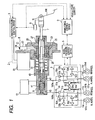
- FIG.1 is a schematic drawing showing an entire configuration of a hydraulic braking device 1 according to a first embodiment of the present invention.
- the FL-wheel indicates the left front wheel
- the FR-wheel indicates the right front wheel
- the RL-wheel indicates the left rear wheel
- the RR-wheel indicates the right rear wheel.
- the broken line with an arrow is a signal line, showing that the signal flows in the direction of the arrow.
- the hydraulic braking device 1 comprises a brake force control device 2 which functions as a brake force control means, a master pressure control device 3 and a master pressure control mechanism 4 both of which are usable in conjunction with a second pressurizing and depressurizing means, a wheel pressure control device 5, a wheel pressure control mechanism 6, an input rod 7 which functions as a first pressurizing and depressurizing means, a brake sensor 8, a master cylinder 9, a reservoir 10, and wheel cylinders 11a-d.
- a brake pedal 100 is usable in conjunction with the first pressurizing and depressurizing means.
- the second pressurizing and depressurizing means includes a primary piston 40 which configures the master cylinder 9.
- the brake force control device 2 is an arithmetic processing circuit which calculates a target brake force that is to be generated at each wheel based an the signal from the brake sensor 8, inter-vehicular distance from a leading vehicle, road information, and vehicle state quantity and transmits a control command to the master pressure control device 3 and the wheel pressure control device 5 based on the calculation results.
- the vehicle state quantity includes, for example, a yaw rate, longitudinal acceleration, lateral acceleration, steering angle, wheel speed, and vehicle speed.
- the brake force control device 2 bidirectionally communicates with the master pressure control device 3 and the wheel pressure control device 5, and those devices share a control command, vehicle state quantity, failure information, and an operating state.
- the master pressure control device 3 is an arithmetic processing circuit which controls a drive motor 20 which configures the master pressure control mechanism 4 based on a control command from the brake force control device 2 and a signal from the brake sensor 8.
- the master pressure control mechanism 4 presses the primary piston 40 according to a control command from the master pressure control device 3.
- the master pressure control mechanism 4 comprises a drive motor 20 which generates rotary torque, a reduction device 21 which amplifies rotary torque of the drive motor 20, and a rotation-translation conversion device 25 which converts rotating power into translational power.
- the wheel pressure control device 5 is an arithmetic processing circuit which controls the wheel pressure control mechanism 6 based on a control command from the brake force control device 2.
- the wheel pressure control mechanism 6 controls the supply of the working fluid pressurized by the master cylinder 9 to each wheel cylinder 11a-d according to a control command from the wheel pressure control device 5.
- the input rod 7 is connected to the brake pedal 100, and its one end is inserted into the primary chamber 42.
- This configuration allows master pressure to be increased by a driver's braking operation; therefore, in the event that the drive motor 20 stops, a prescribed brake force can be ensured. Furthermore, a force in accordance with the master pressure acts upon the brake pedal 100 via the input rod 7 and can be conveyed to a driver as a brake pedal reaction force. Therefore, a device, such as a spring, for generating a brake pedal reaction force is not necessary although it is required if the above-mentioned configuration is not adopted. Consequently, the hydraulic braking device 1 can be small and light-weight, increasing the ease of installation onto a vehicle.
- the brake sensor 8 is a sensor for detecting a brake force required by a driver and is also a stroke sensor for detecting a displacement quantity of the input rod 7.
- the brake sensor 8 be made up of a plurality of stroke sensors. In this configuration, when a signal from a sensor is lost, other sensors can detect and recognize a driver's brake request. Thus, fail-safe operation can be ensured.
- the brake sensor 8 can be a pedal force sensor for detecting a pedal force of the brake pedal 100 and can also be made up of a stroke sensor and a pedal force sensor.
- the master cylinder 9 is a tandem type cylinder comprising two pressurizing chambers: a primary chamber 42 pressurized by a primary piston 40 and a secondary liquid chamber 43 pressurized by a secondary piston 41. It is configured such that working fluid pressurized at each pressurizing chamber due to the thrust of the primary piston 40 is supplied to the wheel pressure control mechanism 6 via master pipes 102a-b.
- the reservoir 10 comprises at least two liquid chambers divided by a partition wall, not shown, and each liquid chamber is connected to each pressurizing chamber of the master cylinder 9 to communicate with each other.
- a wheel cylinder 11a-d comprises a cylinder, a piston, and a pad, those not shown, and the piston is compressed by working fluid supplied by the wheel pressure control mechanism 6 and the pad connected to the piston is pressed by a disc rotor 101a-d.
- the disc rotor 101a-d rotates along with a wheel, not shown. Therefore, brake torque acted upon the disc rotor 101a-d turns into a brake force to be applied between the wheel and the road surface.
- the master pressure control mechanism 4 comprises a drive motor 20, a reduction device 21 and a rotation-translation conversion device 25.
- the drive motor 20 operates by electric power supplied according to a control command from the master pressure control device 3 to generate desired rotary torque.
- a DC motor, a DC brushless motor or an AC motor is suitable for a drive motor 20, and from the viewpoint of controllability, quietness and durability, the DC brushless motor is preferable.
- the drive motor 20 has a position sensor, not shown, and the drive motor 20 is configured such that a signal from the position sensor is inputted into the master pressure control device 3.
- This configuration allows the master pressure control device 3 to calculate a rotation angle of the drive motor 20 based on the signal from the position sensor. And, based on the rotation angle, it is possible to calculate a propulsion quantity of the rotation-translation conversion device 25, that is, a displacement quantity of the primary piston 40.
- the reduction device 21 amplifies rotary torque of the drive motor 20 by the amount of its own reduction ratio.
- gear reduction or pulley reduction is suitable for a reduction method
- the first embodiment adopts the pulley reduction method which comprises a driving pulley 22, a driven pulley 23 and a belt 24.
- the drive motor 20 can be connected directly to the rotation-translation conversion device 25 without providing a reduction device 21. This configuration can avoid problems that occur due to the presence of the reduction device 21 related to reliability, quietness and installation capability.
- the rotation-translation conversion device 25 converts rotating power of the drive motor 20 into translation power thereby pressing the primary piston 40.
- a rack-pinion or a ball screw is suitable for a conversion mechanism, and the first embodiment adopts a method that uses a ball screw.
- a driven pulley 23 is fitted to the outside of the ball screw nut 26, the ball screw nut 26 is rotated by the rotation of the driven pulley 23, the ball screw axis 27 conducts translational motion, and its thrust presses the primary piston 40 via a moving member 28.
- one end of the return spring 29 the other end of which is connected to the fixed portion is fitted to the moving member 28 so that a force applied in the reverse direction of the thrust of the ball screw axis 27 acts upon the ball screw axis 27 via the moving member 28.
- a reaction force of the return spring 29 allows the ball screw axis 27 to return to its initial position, and the master pressure decreases to nearly zero. Consequently, it is possible to avoid a vehicle behavior from becoming unstable as the result of brake force drag.
- amplification ratio (hereafter, referred to as a boosting ratio) is determined to be an arbitrary value according to the displacement quantity ratio between the input rod 7 and the primary piston 40 or the ratio of the cross-sectional area (hereafter, referred to as A IR and A PP , respectively) between the input rod 7 and the primary piston 40.
- the boosting ratio is uniquely determined to be (A IR + A PP )/A IR . That is, a constant boosting ratio can be obtained by setting A IR and A PP based on the necessary boosting ratio and controlling the primary piston 40 so that the displacement quantity becomes equal to the displacement quantity of the input rod 7.
- the displacement quantity of the input rod 7 is detected by a brake sensor 8.
- the displacement quantity of the primary piston 40 is calculated by the master pressure control device 3 based on a signal from a position sensor, not shown.
- the wheel pressure control mechanism 6 comprises gate OUT-valves 50a-b for controlling the supply of the working fluid pressurized by the master cylinder 9 to each wheel cylinder 11a-d; gate IN-valves 51a-b, for controlling the supply of the working fluid pressurized by the master cylinder 9 to pumps 54a-b; IN-valves 52a-d for controlling the supply of the working fluid from the master cylinder 9 or the pumps 54a-b to each wheel cylinder 11a-d; OUT-valves 53a-d for controlling the decompression of the wheel cylinders 11a-d; pumps 54a-b for boosting operating pressure generated by the master cylinder 9; a pump motor 55 for driving the pumps 54a-b; and a master pressure sensor 56 for detecting master pressure.
- a hydraulic pressure control unit for the antilock brake control a hydraulic pressure control unit for the vehicle behavior stabilization control, or a hydraulic pressure control unit for brake-by-wire is suitable.
- the wheel pressure control mechanism 6 comprises two braking systems: a first braking system which is supplied with working fluid from the primary chamber 42 to control a brake force of the FL-wheel and the RR-wheel and a second braking system which is supplied with working fluid from the secondary liquid chamber 43 to control a brake force of the FR-wheel and the RL-wheel. Even if one braking system fails, this configuration ensures a brake force to two diagonal wheels by the operation of the other functioning braking system. Consequently, vehicle behavior can be kept stable.
- gate OUT-valves 50a-b are located between the master cylinder 9 and the IN-valves 52a-d and are opened when working fluid pressurized by the master cylinder 9 is supplied to wheel cylinders 11a-d.
- Gate IN-valves 51a-b are located between the master cylinder 9 and the pumps 54a-b and are opened when working fluid pressurized by the master cylinder 9 is boosted by the pumps 54a-b and supplied to the wheel cylinders 11a-d.
- IN-valves 52a-d are located upstream of the wheel cylinders 11a-d and are opened when working fluid pressurized by the master cylinder 9 or the pumps 54a-b are supplied to the wheel cylinders 11a-d.
- OUT-valves 53a-d are located downstream of the wheel cylinders 11a-d and are opened when the wheel pressure is reduced.
- gate OUT-valves 50a-b, gate IN-valves 51a-b, IN-valves 52a-d, and OUT-valves 53a-d are electromagnetic valves which are opened and closed by turning on and off electric power to the internal solenoid, not shown. The amount of each valve opening is adjusted by electric current controlled by the wheel pressure control device 5.
- gate OUT-valves 50a-b, gate IN-valves 51a-b, IN-valves 52a-d, and OUT-valves 53a-d can be either a normally-open valve or normally-closed valve.
- gate OUT-valves 50a-b and IN-valves 52a-d are normally-open valves
- gate IN-valves 51a-b and OUT-valves 53a-d are normally-closed valves.
- pumps 54a-b can boost the master pressure to apply to the wheel cylinders 11a-d.
- a plunger pump, trochoid pump, or a gear pump is suitable for the pump 54a-b and from the view point of the quietness, the gear pump is preferable.
- the pump motor 55 is operated by electric power supplied based on a control command sent from the wheel pressure control device 5 and drives the pumps 54a-b connected to the pump motor 55 itself.
- a DC motor, DC brushless motor, or an AC motor is suitable for a pump motor 55, and from the viewpoint of the controllability, quietness, and durability, the DC brushless motor is preferable.
- the master pressure sensor 56 which is located downstream of the secondary-side master pipe 102b, is a pressure sensor that detects master pressure.
- the number of master pressure sensors 56 and their installation locations can be arbitrarily determined by considering the controllability and fail-safe operation.
- first routine executed by the brake force control device 2 and the primary piston 40 control executed by a second automatic braking control routine (hereafter, referred to as a second routine), specifically, master pressure control, first control, second control, and third control.
- second routine executed by the brake force control device 2 and the primary piston 40 control executed by a second automatic braking control routine (hereafter, referred to as a second routine), specifically, master pressure control, first control, second control, and third control.
- the master pressure control is to advance and retract the primary piston 40 so as to adjust the operating pressure of the master cylinder 9 to become equal to the hydraulic pressure required by the automatic braking (hereafter, referred to as automatic braking request hydraulic pressure).
- a method in which the primary piston 40 displacement quantity that can achieve automatic braking request hydraulic pressure is obtained based on the relation between the primary piston 40 displacement quantity that has been obtained as a table and the master pressure and the displacement quantity is used as a target value a method which can feed back master pressure detected by the master pressure sensor 56. Either method can be adopted.
- the first control is to displace the primary piston 40 by the amount obtained by multiplying the input rod 7 displacement quantity by a proportional gain (hereafter, referred to as K 1 ).
- K 1 be 1 from the viewpoint of controllability
- a brake force is greater than the brake force generated by a driver's braking operation, for example, due to emergency braking
- K 1 1
- application of the emergency braking can be determined, for example, by whether a time change rate of a signal of the brake sensor 8 exceeds a prescribed value or not.
- the second control is to propel the primary piston 40 by a prescribed offset thereby executing the first control.
- the second control is to be applied when the state must be changed, for example, from the state (hereafter, referred to as two-wheel braking) in which automatic braking operating pressure is applied to only two wheels on either the right side or left side due to the lane departure avoidance control or the obstacle avoidance control to the state (hereafter, referred to as four-wheel braking) in which operating pressure is applied to all of the four wheels according to a driver's brake request.
- this control aims to avoid working fluid from becoming insufficient when two-wheel braking is switched to four-wheel braking. That is, the second control inhibits the decrease in master pressure due to the decrease in the amount of working fluid; consequently, it is possible to avoid a brake force from decreasing in association with the decrease in the master pressure.
- each value of the primary piston 40 displacement quantity that can achieve target brake hydraulic pressure at the two-wheel braking and at the four-wheel braking, respectively, is obtained, and the difference between those two values (displacement quantity at the four-wheel braking minus displacement quantity at the two-wheel braking) is recognized as an offset.
- feedback control which refers to the output of the master pressure sensor 56 is executed so that master pressure will reach the target brake hydraulic pressure when two-wheel braking is switched to four-wheel braking, thereby propelling the primary piston 40.
- target brake hydraulic pressure can be arbitrarily determined according to a driver's brake request; however, for example, it can be automatic braking request hydraulic pressure.
- the first control executed in the second control procedure is the same as the first control mentioned above.
- the primary piston 40 is controlled independently of the first control so that the decrease in master pressure is suppressed when two-wheel braking is switched to four-wheel braking. As a result, it is possible to generate a brake force required by a driver.
- the third control is to displace the primary piston 40 by the amount obtained by multiplying the input rod 7 displacement quantity by a proportional gain (hereafter, referred to as K 3 ).
- the third control is applied specifically when a driver's brake request is a pressure decrease request and is to displace the primary piston 40 so that the master pressure reaches nearly zero at the same time when the input rod 7 displacement quantity reaches nearly zero.
- initial values hereafter, referred to as X IRO and X PPO , respectively
- X IRO and X PPO initial values of displacement quantity of the input rod 7 and the primary piston 40 at the beginning of the third control
- the ratio of X PPO to X IRO is appropriate for K 3 .
- the amount of invalid stroke of the master cylinder 9 can be considered for X PPO .
- the primary piston 40 is controlled so that master pressure reaches nearly zero when a brake force required by a driver reaches nearly zero. As a result, it is possible to generate a brake force required by a driver.
- FIG.2 shows a flowchart of the first routine executed by the brake force control device 2.
- the first routine is applied to the four-wheel braking control, for example, inter-vehicular distance control or collision avoidance control.
- the first routine is repeatedly activated at prescribed time intervals.
- step 100 When the first routine is activated, the operation in step 100 is first executed.
- step 100 whether the automatic braking can be continued or not is determined. If the automatic braking is determined to continue, the operation in step 101 is executed, and if it is determined not to continue, the operation in step 102 is executed.
- step 100 the continuation of automatic braking is determined to be possible, for example, when a driver does not execute a brake operation or when the master pressure is equal to or less than the automatic braking request hydraulic pressure.
- step 101 the master pressure control is executed and operating pressure of the master cylinder 9 is adjusted to become equal to the automatic braking request hydraulic pressure.
- the automatic braking request hydraulic pressure is determined based on the target brake force calculated by the brake force control device 2.
- step 102 whether the automatic braking is to be released or not is determined. If the automatic braking is determined to be released, the operation in step 103 is executed, and if it is determined not to be released, the operation in step 104 is executed.
- step 102 it is determined whether the automatic braking is released or not, for example, based on the vehicle state quantity and the inter-vehicular distance from a leading vehicle.
- step 103 it is determined that a driver's brake request is either a pressure increase request or a pressure hold request. If the driver's brake request is determined to be either a pressure increase request or a pressure retention request, the operation in step 105 is executed, and if it is determined to be neither, the operation in step 106 is executed.
- step 103 it is determined whether the driver's brake request is a pressure increase request, pressure hold request, or a pressure decrease request, for example, based on a time change rate of the input rod 7 displacement quantity detected by the brake sensor 8.
- step 105 the first control is executed and the current routine finishes.
- step 106 the third control is executed and the current routine finishes.
- step 104 in the same manner as step 103, it is determined that a driver's brake request is either a pressure increase request or a pressure hold request. If the driver's brake request is determined to be either a pressure increase request or a pressure retention request, the operation in step 107 is executed, and if it is determined to be neither, the operation in step 108 is executed.
- step 107 the first control is executed and the current routine finishes.
- step 108 the first control is executed.
- step 109 it is determined that the master pressure (P MC ) is either equal to or less than the automatic braking request hydraulic pressure (P DMMD ). If the master pressure (P MC ) is determined to be either equal to or less than the automatic braking request hydraulic pressure (P DMND ), the operation in step 110 is executed, and if it is determined to be neither, the current routine finishes.
- step 110 the automatic braking transition operation is executed.
- the automatic braking transition operation is, for example, to turn on the automatic braking enabled flag.
- the first routine executed by the brake force control device 2 can achieve appropriate automatic braking, and even when a driver executes a brake operation during the automatic braking, the primary piston 40 control is properly selected and executed based on the automatic braking release conditions, a driver's brake request. Therefore, vehicle behavior at the braking is stabilized, increasing the operability of the brake pedal 100.
- FIG.3 shows a time chart of each state quantity when the first routine is activated.
- a situation in which the automatic braking is released in step 102 is assumed.
- appropriate control is selected and executed according to the flowchart shown in FIG.2 .
- the primary piston 40 is controlled by means of the master pressure control so that the master pressure is kept equal to the automatic braking request hydraulic pressure.
- the brake sensor 8 detects a driver's brake request. Therefore, based on this, the automatic braking request hydraulic pressure is reduced to zero.
- the first control method continues to control the primary piston 40.
- prescribed reduction can be maintained.
- the third control method controls the primary piston 40.
- prescribed reduction can be achieved.
- FIG.4 shows a flowchart of the second routine executed by the brake force control device 2.
- the second routine is applied to the two-wheel braking control, for example, lane departure avoidance control or obstacle avoidance control. Furthermore, the second routine is activated repeatedly at prescribed time intervals.
- step 200 When the second routine is activated, the operation in step 200 is first executed.
- step 200 whether the automatic braking can be continued or not is determined. If the automatic braking is determined to continue, the operation in step 201 is executed, and if it is determined not to continue, the operation in step 202 is executed.
- step 200 the continuation of automatic braking is determined to be possible, for example, when a driver does not execute a brake operation or when the master pressure is equal to or less than the automatic braking request hydraulic pressure.
- step 201 it is determined that IN-valves 52a-d of the wheels to which automatic braking is not applied (hereafter, referred to as a non-control wheel) are closed and the decompression of the wheel pressure has been completed. If those valves are closed and the decompression of the wheel pressure has been completed, the operation in step 204 is executed, and if that situation has not been realized, the operation in step 203 is executed.
- step 203 IN-valves 52a-d of non-control wheels are closed and decompression of wheel pressure is executed. By doing so, supply of the working fluid pressurized by the master cylinder 9 to the wheel cylinders 11a-d of the non-control wheels stops, and wheel pressure at the four-wheel braking is reduced to almost zero. Therefore, it is possible to generate a brake force only at the wheels to which automatic braking is applied (hereafter, referred to as a control wheel).
- step 204 master pressure control is executed, and operating pressure of the master cylinder 9 is adjusted to become equal to the automatic braking request hydraulic pressure.
- the automatic braking request hydraulic pressure is determined based on the target brake force calculated by the brake force control device 2.
- step 202 whether the IN-valves 52a-d of non-control wheels have been opened or not is determined. If the IN-valves 52a-d of the non-control wheels have been opened, the operation in step 206 is executed, and if they have not been opened, the operation in step 205 is executed.
- step 205 IN-valves 52a-d of the non-control wheels are to be opened.
- the working fluid pressurized by the master cylinder 9 can be supplied to the wheel cylinders 11a-d of the non-control wheels. Therefore, it is possible to generate a brake force at all four wheels.
- step 206 whether the automatic braking is to be released or not is determined. If the automatic braking is determined to be released, the operation in step 207 is executed, and if the automatic braking is determined not to be released, the operation in step 208 is executed.
- step 206 whether the automatic braking is to be released or not is determined, for example, based on the vehicle state quantity and the inter-vehicular distance from a leading vehicle.
- step 207 it is determined that a driver's brake request is either a pressure increase request or a pressure hold request. If the driver's brake request is determined to be either a pressure increase request or a pressure retention request, the operation in step 209 is executed, and if it is determined to be neither, the operation in step 210 is executed
- step 207 it is determined whether the driver's brake request is a pressure increase request, pressure hold request, or a pressure decrease request, for example, based on a time change rate of the input rod 7 displacement quantity detected by the brake sensor 8.
- step 209 the second control is executed and the current routine finishes.
- step 210 the third control is executed and the current routine finishes.
- step 208 in the same manner as step 207, it is determined that a driver's brake request is either a pressure increase request or a pressure hold request. If the driver's brake request is determined to be either a pressure increase request or a pressure retention request, the operation in step 211 is executed, and if it is determined to be neither, the operation in step 212 is executed
- step 211 the second control is executed and the current routine finishes.
- step 212 the first control is executed.
- step 213 it is determined that the master pressure (P MC ) is either equal to or less than the automatic braking request hydraulic pressure (P DMND ). If the master pressure (P MC ) is determined to be either equal to or less than the automatic braking request hydraulic pressure (P DMND ), the operation in step 214 is executed, and if it is determined to be neither, the current routine finishes.
- step 214 the automatic braking transition operation is executed.
- the automatic braking transition operation is, for example, to turn on the automatic braking enabled flag.
- the second routine executed by the brake force control device 2 can achieve appropriate automatic braking, and even when a driver executes a brake operation during the automatic braking, the primary piston 40 control is properly selected and executed based on the automatic braking release conditions and a driver's brake request. Therefore, vehicle behavior at the braking is stabilized, increasing the operability of the brake pedal 100.
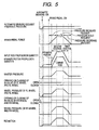
- FIG.5 shows a time chart of each state quantity when the second routine is activated.
- a situation in which the automatic braking is not released in step 206 is assumed.
- appropriate control is selected and executed according to the flowchart shown in FIG.4 .
- a situation in which control wheels are the two wheels on the left side is shown.
- appropriate control is selected and executed according to the flowchart shown in FIG.4 .
- the primary piston 40 is controlled by means of the master pressure control so that the master pressure is kept equal to the automatic braking request hydraulic pressure.
- the brake sensor 8 detects a driver's brake request. Therefore, based on this, IN-valves 52b,d, of the FR-wheel and the RR-wheel, which are non-control wheels, are opened. At this point in time, open timing for each IN-valve 52b,d can be staggered. By doing so, a time change rate of the displacement quantity of the primary piston 40 can be suppressed; consequently, change of the reduction can be further improved.
- the second control method continues to control the primary piston 40.
- prescribed reduction can be maintained.
- the first control method controls the primary piston 40.
- prescribed reduction can be achieved.
- a hydraulic braking device 1 in accordance with a first embodiment of the present invention even when a driver executes a brake operation during the automatic braking, it is possible to generate a brake force required by a driver. Therefore, vehicle behavior at the braking is stabilized, increasing the operability of the brake pedal 100.
- FIG.6 is a schematic drawing showing an entire configuration of a hydraulic braking device 1 according to a second embodiment of the present invention. The same number is assigned to the same portion as that of the first embodiment and description is omitted.
- the second embodiment differs from the first embodiment in that the input rod 7 is not inserted into the primary chamber 42; the conveying member 30 is connected to the moving member 28; the input rod 7 and the conveying member 30 are disposed with a certain gap; and the reaction force generation mechanism 103 is connected to the brake pedal 100.
- the reaction force generation mechanism 103 generates a prescribed reaction force according to a control command from the brake force control device 2 and makes the reaction force act upon the brake pedal 100.
- the first routine executed by the brake force control device 2 and the primary piston 40 control executed by the second routine are the same as those of the first embodiment. Therefore, in the same manner as the first embodiment, even when a driver executes a brake operation during the automatic braking, it is possible to generate a brake force required by a driver.
- a driver's brake pedal 100 force is conveyed to the primary piston 40 via the input rod 7, conveying member 30, and the moving member 28. Therefore, the master pressure increases thereby ensuring a prescribed brake force.
- reaction force generation mechanism 103 can arbitrarily determine the brake pedal 100 reaction force, it is easy to change the operational feeling of the brake pedal 100.
Landscapes
- Engineering & Computer Science (AREA)
- Transportation (AREA)
- Mechanical Engineering (AREA)
- Physics & Mathematics (AREA)
- Fluid Mechanics (AREA)
- Regulating Braking Force (AREA)
- Braking Systems And Boosters (AREA)
Claims (5)
- Dispositif de freinage hydraulique (1) comprenant
un maître-cylindre (9),
un premier moyen de pressurisation et de dépressurisation (7, 100) pour pressuriser et dépressuriser le maître-cylindre (9),
un second moyen de pressurisation et de dépressurisation (4, 40) pour pressuriser et dépressuriser le maître-cylindre (9) indépendamment du premier moyen de pressurisation et de dépressurisation (7),
un moyen de commande de force de freinage (2) pour calculer une force de freinage cible et déterminer une pression cible du maître-cylindre en se basant sur la force de freinage cible calculée, et
une pluralité de cylindres de roues (11a-11d) actionnés par une pression de fluide de travail appliquée par le maître-cylindre (9), dans lequel
le moyen de commande de force de freinage (2) est adapté à exécuter une commande de pression maître adaptée à commander le second moyen de pressurisation et de dépressurisation en accord avec la pression cible dans le maître-cylindre,
caractérisé en ce que
le moyen de commande de force de freinage (2) est en outre adapté à exécuter une pluralité de commandes de freinage, dans lesquelles
le moyen de commande de force de freinage (2) est adapté à sélectionner et à démarrer l'une des commandes de freinage quand le premier moyen de pressurisation et de dépressurisation (7, 100) est actionné par une opération de freinage du conducteur pendant la commande de pression maître, et dans lequel
le moyen de commande de force de freinage (2) est adapté à commander le second moyen de pressurisation et de dépressurisation (4, 40) dans l'état de commande de freinage en accord avec trois commandes de freinage :- une première commande de freinage qui déplace le second moyen de pressurisation et de dépressurisation (40) d'une quantité proportionnelle à une quantité de déplacement du premier moyen de pressurisation et de dépressurisation (7, 100),- une seconde commande de freinage qui déplace le second moyen de pressurisation et de dépressurisation (40) d'une quantité proportionnelle à une quantité de déplacement du premier moyen de pressurisation et de dépressurisation (7, 100) plus une quantité de déplacement prescrite, et- une troisième commande de freinage qui déplace le second moyen de pressurisation et de dépressurisation (40) de telle sorte que le second moyen de pressurisation et de dépressurisation (40) relâche la pression sur le maître-cylindre dans l'état dans lequel la quantité de déplacement du premier moyen de pressurisation et de dépressurisation (7, 100) est ramenée à zéro. - Dispositif de freinage hydraulique (1) selon la revendication 1, dans lequel
le moyen de commande de force de freinage (2) est adapté, quand tous les cylindres de roues (11a-11d) sont actionnés dans la commande de pression maître, après avoir commuté vers l'une des commandes de freinage, pour sélectionner la première commande de freinage quand le premier moyen de pressurisation et de dépressurisation (7, 100) fonctionne pour pressuriser le maître-cylindre (9), et pour sélectionner la première ou la troisième commande de freinage quand le premier moyen de pressurisation et de dépressurisation (7, 100) fonctionne pour dépressuriser le maître-cylindre (9). - Dispositif de freinage hydraulique (1) selon la revendication 1, dans lequel
le moyen de commande de force de freinage (2) est adapté, quand un ou plusieurs cylindres de roues (11a-11d) ne sont pas actionnés dans la commande de pression maître, après avoir commuté vers l'une des commandes de freinage, pour sélectionner la seconde commande de freinage quand le premier moyen de pressurisation et de dépressurisation (7, 100) fonctionne pour pressuriser le maître-cylindre (9), et pour sélectionner la première ou la troisième commande de freinage quand le premier moyen de pressurisation et de dépressurisation (7, 100) fonctionne pour dépressuriser le maître-cylindre (9). - Dispositif de freinage hydraulique (1) selon l'une au moins des revendications 1 à 3, dans lequel
le premier moyen de pressurisation et de dépressurisation (7, 100) pressurise et dépressurise le maître-cylindre (9) en actionnant le second moyen de pressurisation et de dépressurisation (4, 40). - Automobile comprenant un dispositif de freinage hydraulique (1) selon l'une au moins des revendications 1 à 4.
Applications Claiming Priority (1)
| Application Number | Priority Date | Filing Date | Title |
|---|---|---|---|
| JP2007195317A JP4881807B2 (ja) | 2007-07-27 | 2007-07-27 | 液圧ブレーキ装置 |
Publications (3)
| Publication Number | Publication Date |
|---|---|
| EP2019010A2 EP2019010A2 (fr) | 2009-01-28 |
| EP2019010A3 EP2019010A3 (fr) | 2010-11-10 |
| EP2019010B1 true EP2019010B1 (fr) | 2013-05-22 |
Family
ID=39828998
Family Applications (1)
| Application Number | Title | Priority Date | Filing Date |
|---|---|---|---|
| EP08012954.7A Active EP2019010B1 (fr) | 2007-07-27 | 2008-07-17 | Dispositif de freinage hydraulique |
Country Status (3)
| Country | Link |
|---|---|
| US (1) | US20090026835A1 (fr) |
| EP (1) | EP2019010B1 (fr) |
| JP (1) | JP4881807B2 (fr) |
Families Citing this family (23)
| Publication number | Priority date | Publication date | Assignee | Title |
|---|---|---|---|---|
| JP5107075B2 (ja) * | 2008-01-31 | 2012-12-26 | トヨタ自動車株式会社 | 制動装置 |
| JP5066004B2 (ja) * | 2008-06-06 | 2012-11-07 | 日立オートモティブシステムズ株式会社 | ブレーキシステム |
| JP5304274B2 (ja) * | 2009-01-29 | 2013-10-02 | 日産自動車株式会社 | 車両用制動制御装置 |
| US9233673B2 (en) * | 2009-04-14 | 2016-01-12 | Honda Motor Co., Ltd. | BBW brake device |
| DE102009028034A1 (de) * | 2009-07-27 | 2011-02-03 | Robert Bosch Gmbh | Hydraulischer Hauptbremszylinder |
| JP5400716B2 (ja) * | 2010-06-30 | 2014-01-29 | 日立建機株式会社 | 電動車両の駆動力制御装置 |
| DE102010042694B4 (de) * | 2010-07-27 | 2025-07-10 | Robert Bosch Gmbh | Kopplungsvorrichtung zum Verbinden eines Bremseingabeelements mit einem Hauptbremszylinder und Verfahren zum Betreiben einer derartigen Kopplungsvorrichtung |
| US9878697B2 (en) * | 2010-09-17 | 2018-01-30 | Ipgate Ag | Actuating device for a motor vehicle brake system |
| US9061669B2 (en) * | 2010-12-01 | 2015-06-23 | Toyota Jidosha Kabushiki Kaisha | Hydraulic brake system |
| DE102011101066B4 (de) * | 2011-05-10 | 2024-08-01 | Zf Active Safety Gmbh | Hydraulische Fahrzeug-Bremsanlage mit elektromechanischem Aktuator |
| DE102011112515A1 (de) * | 2011-08-29 | 2013-02-28 | Ipgate Ag | Betätigungsvorrichtung für eine Kraftfahrzeug-Bremsanlage |
| JP5610308B2 (ja) * | 2011-09-27 | 2014-10-22 | 豊田合成株式会社 | ガラスラン |
| DE102011083827A1 (de) * | 2011-09-30 | 2013-04-04 | Robert Bosch Gmbh | Primärkolbenbaugruppe für einen Hauptbremszylinder eines Bremssystems eines Fahrzeugs, Herstellungsverfahren für ein Bremsgerät und Verfahren zum Betreiben eines Bremsgeräts |
| JP5673639B2 (ja) * | 2012-03-22 | 2015-02-18 | 株式会社アドヴィックス | 電動駐車ブレーキ制御装置 |
| JP5814171B2 (ja) * | 2012-03-30 | 2015-11-17 | トヨタ自動車株式会社 | シリンダ装置および液圧ブレーキシステム |
| EP2650607B1 (fr) | 2012-04-13 | 2014-07-23 | Hella KGaA Hueck & Co | Lumière DEL modulaire |
| US9248815B2 (en) | 2012-12-07 | 2016-02-02 | Robert Bosch Gmbh | System and method for emergency braking |
| US9409559B2 (en) * | 2013-03-13 | 2016-08-09 | Autoliv Asp, Inc. | Vehicle braking system with electric brake booster |
| US9969374B2 (en) | 2013-05-31 | 2018-05-15 | Ford Global Technologies, Llc | Control and delivery of hydraulic fluid in vehicle braking system |
| JP6063352B2 (ja) * | 2013-05-31 | 2017-01-18 | 富士重工業株式会社 | 車両用制御装置 |
| KR101764401B1 (ko) * | 2013-12-27 | 2017-08-14 | 주식회사 만도 | 드래그 저감 기능을 갖는 브레이크 시스템 및 그의 제어방법 |
| JP2016002977A (ja) * | 2014-06-19 | 2016-01-12 | 日立オートモティブシステムズ株式会社 | ブレーキ装置 |
| KR102731648B1 (ko) * | 2020-02-25 | 2024-11-19 | 에이치엘만도 주식회사 | 브레이크 페달 이동장치 |
Citations (3)
| Publication number | Priority date | Publication date | Assignee | Title |
|---|---|---|---|---|
| EP0379329A2 (fr) * | 1989-01-18 | 1990-07-25 | LUCAS INDUSTRIES public limited company | Amplificateurs activés par pression de fluide dans un système de freinage de véhicule |
| US20020158510A1 (en) * | 2001-04-26 | 2002-10-31 | Kazuo Kobayashi | Electrically driven brake booster |
| JP2002356149A (ja) * | 2001-05-31 | 2002-12-10 | Tokico Ltd | 制御型ブレーキブースタおよびアダプティブクルーズコントローラの制御解除プログラム |
Family Cites Families (21)
| Publication number | Priority date | Publication date | Assignee | Title |
|---|---|---|---|---|
| DE3240680A1 (de) * | 1982-11-04 | 1984-05-10 | Robert Bosch Gmbh, 7000 Stuttgart | Hauptbremszylinder |
| JPS6092151A (ja) * | 1983-10-25 | 1985-05-23 | Mazda Motor Corp | 自動車の電磁サ−ボブレ−キ装置 |
| DE3417018A1 (de) * | 1984-05-09 | 1985-11-14 | Alfred Teves Gmbh, 6000 Frankfurt | Hydraulische bremsanlage mit schlupfregelung |
| DE3526556A1 (de) * | 1985-07-25 | 1987-01-29 | Teves Gmbh Alfred | Bremsanlage mit hydraulischer bremskraftverstaerkung |
| JPH07223529A (ja) * | 1994-02-10 | 1995-08-22 | Toyota Motor Corp | アンチロック型ブレーキシステム |
| JPH08198075A (ja) * | 1995-01-30 | 1996-08-06 | Mazda Motor Corp | 車両の自動ブレーキ装置 |
| DE19624794A1 (de) * | 1996-06-21 | 1998-01-02 | Teves Gmbh Alfred | Bremsanlage für Kraftfahrzeuge |
| GB2321681B (en) * | 1997-02-03 | 2000-11-29 | Lucas Industries Ltd | Electronic braking system for vehicles |
| JP3644222B2 (ja) * | 1997-11-28 | 2005-04-27 | トヨタ自動車株式会社 | 制動制御装置 |
| EP1044124A1 (fr) * | 1998-01-07 | 2000-10-18 | Continental Teves AG & Co. oHG | Systeme de regulation de la dynamique du mouvement de vehicules et procede d'exploitation d'un tel systeme |
| EP1078833B1 (fr) * | 1999-08-25 | 2005-11-16 | Continental Teves & Co. oHG | Système de freinage pour véhicule automobile et procédé de fonctionnement d'un système de freinage |
| JP2003182550A (ja) * | 2001-12-25 | 2003-07-03 | Aisin Seiki Co Ltd | 車両の制動制御装置 |
| EP1521696B1 (fr) * | 2002-07-09 | 2006-12-27 | Continental Teves AG & Co. oHG | Dispositif d'actionnement de frein a commande electrique |
| EP1470979B1 (fr) * | 2003-04-24 | 2006-12-27 | Nissan Motor Company Limited | Système de freinage pour véhicule |
| US8789896B2 (en) * | 2004-10-08 | 2014-07-29 | Cequent Electrical Products | Brake control unit |
| JP4300365B2 (ja) * | 2004-10-13 | 2009-07-22 | 日産自動車株式会社 | 車両の制動力制御装置 |
| DE102005017958A1 (de) * | 2004-10-15 | 2006-04-27 | Continental Teves Ag & Co. Ohg | Bremsanlage für Kraftfahrzeuge |
| US7367187B2 (en) * | 2005-06-30 | 2008-05-06 | Hitachi, Ltd. | Electrically actuated brake booster |
| CN101287633B (zh) * | 2005-09-26 | 2011-09-07 | 株式会社日立制作所 | 电动助力装置 |
| JP2007145285A (ja) * | 2005-11-30 | 2007-06-14 | Advics:Kk | 車両用ブレーキ制御装置 |
| US7597409B2 (en) * | 2006-04-03 | 2009-10-06 | Advics Co., Ltd. | Control unit of brake apparatus for vehicle |
-
2007
- 2007-07-27 JP JP2007195317A patent/JP4881807B2/ja active Active
-
2008
- 2008-07-17 EP EP08012954.7A patent/EP2019010B1/fr active Active
- 2008-07-24 US US12/179,440 patent/US20090026835A1/en not_active Abandoned
Patent Citations (3)
| Publication number | Priority date | Publication date | Assignee | Title |
|---|---|---|---|---|
| EP0379329A2 (fr) * | 1989-01-18 | 1990-07-25 | LUCAS INDUSTRIES public limited company | Amplificateurs activés par pression de fluide dans un système de freinage de véhicule |
| US20020158510A1 (en) * | 2001-04-26 | 2002-10-31 | Kazuo Kobayashi | Electrically driven brake booster |
| JP2002356149A (ja) * | 2001-05-31 | 2002-12-10 | Tokico Ltd | 制御型ブレーキブースタおよびアダプティブクルーズコントローラの制御解除プログラム |
Also Published As
| Publication number | Publication date |
|---|---|
| US20090026835A1 (en) | 2009-01-29 |
| EP2019010A2 (fr) | 2009-01-28 |
| EP2019010A3 (fr) | 2010-11-10 |
| JP2009029265A (ja) | 2009-02-12 |
| JP4881807B2 (ja) | 2012-02-22 |
Similar Documents
| Publication | Publication Date | Title |
|---|---|---|
| EP2019010A2 (fr) | Dispositif de freinage hydraulique | |
| JP5065955B2 (ja) | ブレーキ制御システム | |
| US11820342B2 (en) | Hydraulic motor vehicle braking system and method for operating same | |
| JP5514805B2 (ja) | ブレーキ制御装置 | |
| US8672808B2 (en) | Brake control system | |
| US8348352B2 (en) | Brake control apparatus and method | |
| CN102463976B (zh) | 电动助力装置 | |
| US20150061362A1 (en) | Brake control apparatus | |
| US20130025273A1 (en) | Electric booster | |
| US8602507B2 (en) | Method for controlling the activation of a hydraulic vehicle brake system and electromechanical brake booster | |
| JP5061051B2 (ja) | ブレーキ制御装置 | |
| KR20150091244A (ko) | 브레이크 제어 장치 | |
| US20120074771A1 (en) | Method for Operating a Hydraulic Vehicle Braking System that has an Anti-Lock Control Unit | |
| KR20130035204A (ko) | 브레이크 제어 장치 | |
| WO2016136671A1 (fr) | Dispositif de commande de frein | |
| KR101281999B1 (ko) | 차량의 능동 유압 부스트 장치 및 그 제어 방법 | |
| JP5428201B2 (ja) | 電動倍力式液圧ブレーキ装置 | |
| JP6221118B2 (ja) | ブレーキシステム | |
| KR20210117472A (ko) | 브레이크 제어장치 및 그 제어방법 | |
| CN121794168A (zh) | 液压控制装置及制动液压控制单元的控制方法 |
Legal Events
| Date | Code | Title | Description |
|---|---|---|---|
| PUAI | Public reference made under article 153(3) epc to a published international application that has entered the european phase |
Free format text: ORIGINAL CODE: 0009012 |
|
| AK | Designated contracting states |
Kind code of ref document: A2 Designated state(s): AT BE BG CH CY CZ DE DK EE ES FI FR GB GR HR HU IE IS IT LI LT LU LV MC MT NL NO PL PT RO SE SI SK TR |
|
| AX | Request for extension of the european patent |
Extension state: AL BA MK RS |
|
| 17P | Request for examination filed |
Effective date: 20090420 |
|
| PUAL | Search report despatched |
Free format text: ORIGINAL CODE: 0009013 |
|
| AK | Designated contracting states |
Kind code of ref document: A3 Designated state(s): AT BE BG CH CY CZ DE DK EE ES FI FR GB GR HR HU IE IS IT LI LT LU LV MC MT NL NO PL PT RO SE SI SK TR |
|
| AX | Request for extension of the european patent |
Extension state: AL BA MK RS |
|
| AKX | Designation fees paid |
Designated state(s): DE FR GB IT |
|
| 17Q | First examination report despatched |
Effective date: 20110819 |
|
| GRAP | Despatch of communication of intention to grant a patent |
Free format text: ORIGINAL CODE: EPIDOSNIGR1 |
|
| RIC1 | Information provided on ipc code assigned before grant |
Ipc: B60T 13/74 20060101ALN20121105BHEP Ipc: B60T 8/40 20060101AFI20121105BHEP |
|
| GRAS | Grant fee paid |
Free format text: ORIGINAL CODE: EPIDOSNIGR3 |
|
| GRAA | (expected) grant |
Free format text: ORIGINAL CODE: 0009210 |
|
| AK | Designated contracting states |
Kind code of ref document: B1 Designated state(s): DE FR GB IT |
|
| REG | Reference to a national code |
Ref country code: GB Ref legal event code: FG4D |
|
| RAP2 | Party data changed (patent owner data changed or rights of a patent transferred) |
Owner name: HITACHI, LTD. |
|
| REG | Reference to a national code |
Ref country code: DE Ref legal event code: R096 Ref document number: 602008024683 Country of ref document: DE Effective date: 20130718 |
|
| PG25 | Lapsed in a contracting state [announced via postgrant information from national office to epo] |
Ref country code: IT Free format text: LAPSE BECAUSE OF FAILURE TO SUBMIT A TRANSLATION OF THE DESCRIPTION OR TO PAY THE FEE WITHIN THE PRESCRIBED TIME-LIMIT Effective date: 20130522 |
|
| PLBE | No opposition filed within time limit |
Free format text: ORIGINAL CODE: 0009261 |
|
| STAA | Information on the status of an ep patent application or granted ep patent |
Free format text: STATUS: NO OPPOSITION FILED WITHIN TIME LIMIT |
|
| 26N | No opposition filed |
Effective date: 20140225 |
|
| REG | Reference to a national code |
Ref country code: DE Ref legal event code: R097 Ref document number: 602008024683 Country of ref document: DE Effective date: 20140225 |
|
| REG | Reference to a national code |
Ref country code: FR Ref legal event code: PLFP Year of fee payment: 9 |
|
| REG | Reference to a national code |
Ref country code: FR Ref legal event code: PLFP Year of fee payment: 10 |
|
| REG | Reference to a national code |
Ref country code: FR Ref legal event code: PLFP Year of fee payment: 11 |
|
| REG | Reference to a national code |
Ref country code: DE Ref legal event code: R081 Ref document number: 602008024683 Country of ref document: DE Owner name: HITACHI ASTEMO, LTD., HITACHINAKA-SHI, JP Free format text: FORMER OWNER: HITACHI AUTOMOTIVE SYSTEMS, LTD., HITACHINAKA-SHI, IBARAKI, JP Ref country code: DE Ref legal event code: R081 Ref document number: 602008024683 Country of ref document: DE Owner name: HITACHI ASTEMO, LTD., HITACHINAKA-SHI, JP Free format text: FORMER OWNER: HITACHI, LTD., TOKYO, JP |
|
| REG | Reference to a national code |
Ref country code: GB Ref legal event code: 732E Free format text: REGISTERED BETWEEN 20210930 AND 20211006 |
|
| PGFP | Annual fee paid to national office [announced via postgrant information from national office to epo] |
Ref country code: GB Payment date: 20250529 Year of fee payment: 18 |
|
| PGFP | Annual fee paid to national office [announced via postgrant information from national office to epo] |
Ref country code: FR Payment date: 20250610 Year of fee payment: 18 |
|
| PGFP | Annual fee paid to national office [announced via postgrant information from national office to epo] |
Ref country code: DE Payment date: 20250528 Year of fee payment: 18 |