EP2019012B1 - Transmission à rapports multiples - Google Patents
Transmission à rapports multiples Download PDFInfo
- Publication number
- EP2019012B1 EP2019012B1 EP08017785A EP08017785A EP2019012B1 EP 2019012 B1 EP2019012 B1 EP 2019012B1 EP 08017785 A EP08017785 A EP 08017785A EP 08017785 A EP08017785 A EP 08017785A EP 2019012 B1 EP2019012 B1 EP 2019012B1
- Authority
- EP
- European Patent Office
- Prior art keywords
- transmission
- ratio
- speed
- gearbox
- range
- Prior art date
- Legal status (The legal status is an assumption and is not a legal conclusion. Google has not performed a legal analysis and makes no representation as to the accuracy of the status listed.)
- Expired - Lifetime
Links
Images

Classifications
-
- B—PERFORMING OPERATIONS; TRANSPORTING
- B60—VEHICLES IN GENERAL
- B60K—ARRANGEMENT OR MOUNTING OF PROPULSION UNITS OR OF TRANSMISSIONS IN VEHICLES; ARRANGEMENT OR MOUNTING OF PLURAL DIVERSE PRIME-MOVERS IN VEHICLES; AUXILIARY DRIVES FOR VEHICLES; INSTRUMENTATION OR DASHBOARDS FOR VEHICLES; ARRANGEMENTS IN CONNECTION WITH COOLING, AIR INTAKE, GAS EXHAUST OR FUEL SUPPLY OF PROPULSION UNITS IN VEHICLES
- B60K20/00—Arrangement or mounting of change-speed gearing control devices in vehicles
- B60K20/02—Arrangement or mounting of change-speed gearing control devices in vehicles of initiating means
-
- B—PERFORMING OPERATIONS; TRANSPORTING
- B60—VEHICLES IN GENERAL
- B60K—ARRANGEMENT OR MOUNTING OF PROPULSION UNITS OR OF TRANSMISSIONS IN VEHICLES; ARRANGEMENT OR MOUNTING OF PLURAL DIVERSE PRIME-MOVERS IN VEHICLES; AUXILIARY DRIVES FOR VEHICLES; INSTRUMENTATION OR DASHBOARDS FOR VEHICLES; ARRANGEMENTS IN CONNECTION WITH COOLING, AIR INTAKE, GAS EXHAUST OR FUEL SUPPLY OF PROPULSION UNITS IN VEHICLES
- B60K35/00—Instruments specially adapted for vehicles; Arrangement of instruments in or on vehicles
- B60K35/10—Input arrangements, i.e. from user to vehicle, associated with vehicle functions or specially adapted therefor
-
- F—MECHANICAL ENGINEERING; LIGHTING; HEATING; WEAPONS; BLASTING
- F16—ENGINEERING ELEMENTS AND UNITS; GENERAL MEASURES FOR PRODUCING AND MAINTAINING EFFECTIVE FUNCTIONING OF MACHINES OR INSTALLATIONS; THERMAL INSULATION IN GENERAL
- F16H—GEARING
- F16H59/00—Control inputs to control units of change-speed- or reversing-gearings for conveying rotary motion
- F16H59/02—Selector apparatus
-
- F—MECHANICAL ENGINEERING; LIGHTING; HEATING; WEAPONS; BLASTING
- F16—ENGINEERING ELEMENTS AND UNITS; GENERAL MEASURES FOR PRODUCING AND MAINTAINING EFFECTIVE FUNCTIONING OF MACHINES OR INSTALLATIONS; THERMAL INSULATION IN GENERAL
- F16H—GEARING
- F16H59/00—Control inputs to control units of change-speed- or reversing-gearings for conveying rotary motion
- F16H59/02—Selector apparatus
- F16H59/04—Ratio selector apparatus
-
- F—MECHANICAL ENGINEERING; LIGHTING; HEATING; WEAPONS; BLASTING
- F16—ENGINEERING ELEMENTS AND UNITS; GENERAL MEASURES FOR PRODUCING AND MAINTAINING EFFECTIVE FUNCTIONING OF MACHINES OR INSTALLATIONS; THERMAL INSULATION IN GENERAL
- F16H—GEARING
- F16H59/00—Control inputs to control units of change-speed- or reversing-gearings for conveying rotary motion
- F16H59/02—Selector apparatus
- F16H59/08—Range selector apparatus
-
- F—MECHANICAL ENGINEERING; LIGHTING; HEATING; WEAPONS; BLASTING
- F16—ENGINEERING ELEMENTS AND UNITS; GENERAL MEASURES FOR PRODUCING AND MAINTAINING EFFECTIVE FUNCTIONING OF MACHINES OR INSTALLATIONS; THERMAL INSULATION IN GENERAL
- F16H—GEARING
- F16H59/00—Control inputs to control units of change-speed- or reversing-gearings for conveying rotary motion
- F16H59/74—Inputs being a function of engine parameters
-
- F—MECHANICAL ENGINEERING; LIGHTING; HEATING; WEAPONS; BLASTING
- F16—ENGINEERING ELEMENTS AND UNITS; GENERAL MEASURES FOR PRODUCING AND MAINTAINING EFFECTIVE FUNCTIONING OF MACHINES OR INSTALLATIONS; THERMAL INSULATION IN GENERAL
- F16H—GEARING
- F16H61/00—Control functions within control units of change-speed- or reversing-gearings for conveying rotary motion ; Control of exclusively fluid gearing, friction gearing, gearings with endless flexible members or other particular types of gearing
- F16H61/02—Control functions within control units of change-speed- or reversing-gearings for conveying rotary motion ; Control of exclusively fluid gearing, friction gearing, gearings with endless flexible members or other particular types of gearing characterised by the signals used
- F16H61/0202—Control functions within control units of change-speed- or reversing-gearings for conveying rotary motion ; Control of exclusively fluid gearing, friction gearing, gearings with endless flexible members or other particular types of gearing characterised by the signals used the signals being electric
-
- F—MECHANICAL ENGINEERING; LIGHTING; HEATING; WEAPONS; BLASTING
- F16—ENGINEERING ELEMENTS AND UNITS; GENERAL MEASURES FOR PRODUCING AND MAINTAINING EFFECTIVE FUNCTIONING OF MACHINES OR INSTALLATIONS; THERMAL INSULATION IN GENERAL
- F16H—GEARING
- F16H61/00—Control functions within control units of change-speed- or reversing-gearings for conveying rotary motion ; Control of exclusively fluid gearing, friction gearing, gearings with endless flexible members or other particular types of gearing
- F16H61/02—Control functions within control units of change-speed- or reversing-gearings for conveying rotary motion ; Control of exclusively fluid gearing, friction gearing, gearings with endless flexible members or other particular types of gearing characterised by the signals used
- F16H61/0202—Control functions within control units of change-speed- or reversing-gearings for conveying rotary motion ; Control of exclusively fluid gearing, friction gearing, gearings with endless flexible members or other particular types of gearing characterised by the signals used the signals being electric
- F16H61/0248—Control units where shifting is directly initiated by the driver, e.g. semi-automatic transmissions
-
- F—MECHANICAL ENGINEERING; LIGHTING; HEATING; WEAPONS; BLASTING
- F16—ENGINEERING ELEMENTS AND UNITS; GENERAL MEASURES FOR PRODUCING AND MAINTAINING EFFECTIVE FUNCTIONING OF MACHINES OR INSTALLATIONS; THERMAL INSULATION IN GENERAL
- F16H—GEARING
- F16H61/00—Control functions within control units of change-speed- or reversing-gearings for conveying rotary motion ; Control of exclusively fluid gearing, friction gearing, gearings with endless flexible members or other particular types of gearing
- F16H61/70—Control functions within control units of change-speed- or reversing-gearings for conveying rotary motion ; Control of exclusively fluid gearing, friction gearing, gearings with endless flexible members or other particular types of gearing specially adapted for change-speed gearing in group arrangement, i.e. with separate change-speed gear trains arranged in series, e.g. range or overdrive-type gearing arrangements
-
- B—PERFORMING OPERATIONS; TRANSPORTING
- B60—VEHICLES IN GENERAL
- B60K—ARRANGEMENT OR MOUNTING OF PROPULSION UNITS OR OF TRANSMISSIONS IN VEHICLES; ARRANGEMENT OR MOUNTING OF PLURAL DIVERSE PRIME-MOVERS IN VEHICLES; AUXILIARY DRIVES FOR VEHICLES; INSTRUMENTATION OR DASHBOARDS FOR VEHICLES; ARRANGEMENTS IN CONNECTION WITH COOLING, AIR INTAKE, GAS EXHAUST OR FUEL SUPPLY OF PROPULSION UNITS IN VEHICLES
- B60K2360/00—Indexing scheme associated with groups B60K35/00 or B60K37/00 relating to details of instruments or dashboards
- B60K2360/126—Rotatable input devices for instruments
-
- F—MECHANICAL ENGINEERING; LIGHTING; HEATING; WEAPONS; BLASTING
- F16—ENGINEERING ELEMENTS AND UNITS; GENERAL MEASURES FOR PRODUCING AND MAINTAINING EFFECTIVE FUNCTIONING OF MACHINES OR INSTALLATIONS; THERMAL INSULATION IN GENERAL
- F16H—GEARING
- F16H59/00—Control inputs to control units of change-speed- or reversing-gearings for conveying rotary motion
- F16H59/02—Selector apparatus
- F16H59/08—Range selector apparatus
- F16H2059/081—Range selector apparatus using knops or discs for rotary range selection
-
- Y—GENERAL TAGGING OF NEW TECHNOLOGICAL DEVELOPMENTS; GENERAL TAGGING OF CROSS-SECTIONAL TECHNOLOGIES SPANNING OVER SEVERAL SECTIONS OF THE IPC; TECHNICAL SUBJECTS COVERED BY FORMER USPC CROSS-REFERENCE ART COLLECTIONS [XRACs] AND DIGESTS
- Y10—TECHNICAL SUBJECTS COVERED BY FORMER USPC
- Y10T—TECHNICAL SUBJECTS COVERED BY FORMER US CLASSIFICATION
- Y10T74/00—Machine element or mechanism
- Y10T74/19—Gearing
- Y10T74/19219—Interchangeably locked
- Y10T74/19251—Control mechanism
- Y10T74/19256—Automatic
- Y10T74/1926—Speed responsive
Definitions
- This invention relates to multi-ratio tractor transmissions which have an automated mode of operation.
- Such a transmission is known, for example, from EP 0 547598A .
- An infinitely variable transmission is known from US 2002/0010534 A .
- multi-ratio tractor transmission system comprising a series arrangement of a speed changing gearbox and a range changing gearbox, the system being selectively operable in a field working automatic mode and a road working automatic mode, wherein the transmission can only operate automatically within its speed change gearbox when the system is operating in the field working automatic mode.
- the speed changing box may be a multi-ratio epicyclic unit and the range change box may be a synchromesh unit. With such series arrangements it is desirable to provide some so-called "speed matching" capability when the overall control of the active transmission ratio ensures that when a range change is made the ratio selected in the speed changing box is also adjusted to ensure that the ratio provided by the overall transmission is the next overall available ratio in the transmission.
- the transmission system may be operable in a speed-matching mode wherein the ratio of the speed changing gearbox is automatically selected so as to deliver the next overall available ratio in the transmission in response to the operator changing the ratio of the range changing gearbox. Therefore, when a range change occurs, the overall control of the transmission adjusts the ratio of the speed changing box to ensure that the ratio provided by the overall transmission is the next overall available ratio in the transmission. When in these "speed matching" zones the ratio changes must be commanded by the operator.
- the engine speed at which the transmission changes up in ratio when operating automatically can being selectable by the operator.
- the engine speed at which the transmission changes up in ratio may be selectable within a pre-defined range. Typically this change-up speed may be variable between say 1600rpm and 2200rpm.
- the speed at which the transmission changes down when in the automatic mode may conveniently be linked to the selected change-up speed.
- the change down may be arranged to be initiated when the engine speed has fallen to 20% below the selected change-up speed.
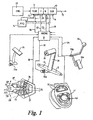
- FIG. 1 this show in diagrammatic form the controls of a multi-ratio tractor transmission in which an engine 10 drives a multi-ratio epicyclic gearbox 11 in series with forward and reverse clutches F and R and a multi-ratio synchromesh gearbox 12 whose output 13 drives the wheels of the tractor via suitable differentials and final drive gears etc which are not shown.
- the epicyclical gearbox 11 will provide six ratios and the synchromesh gearbox 12 will provide four range ratios. These ratios are changed hydraulically by pressurised fluid provided from a hydraulic source 14 which includes a hydraulic pump etc.
- the ratio changes are controlled by solenoid operated hydraulic control valves 15 associated with epicyclic gearbox 10 and similar valves 16 associated with synchromesh box 12. These valves are in turn operated by electrical signals from a microprocessor control unit 17 via lines 18 and 19 respectively.
- the forward and reverse clutches F and R are also hydraulically operated with pressure from source 14 and are controlled by solenoid operated valves 20 and 21 respectively via lines 22 and 23.
- Microprocessor control unit 17 receives inputs from the following driver operated controls and from other sensors on the tractor.
- a sensor (not shown) which indicates the position of lever 24 is connected to microprocessor control unit 17 via line 28.
- Lever 24 has a central neutral zone 25 (shown in figure 1 ), a forward zone of operation 26 and a reverse zone of operation 27. When in the forward zone of operation 26 the associated transmission can be changed up a ratio in the forward direction each time the lever 24 is moved in the UF direction and down a ration each time the lever 24 is moved in the DF direction.
- the associated transmission can be changed up a ratio in the reverse direction each time the lever 24 is moved in the UR direction and down a ratio each time the lever 24 is moved in the DR direction.
- These movements of lever 24 trigger all the necessary operations of the ratio changing valves 15 and 16 and the clutch valves 20 and 21 to make the requested ratio changes
- the lever 24 also disengages the operative forward or reverse clutch (F,R) if the lever is pulled up towards the operator, as indicated by arrow 24a.
- the transmission is also controllable by a control lever 30 which when moved in the upward direction U and held displaced in this direction causes the transmission to progressively shift up through the six ratios provided by epicyclical gearbox 11 and, if a range change is required in synchromesh gearbox 12, the drive can be disconnected by pressing button 31 on the end of lever 30 to disengage either the forward or reverse drive clutch F or R depending on which clutch is currently operative.
- each pressing of button 31 causes the transmission to shift up a range in the gearbox 12.
- the transmission can he caused to shift quickly up through the ratios provided by box 11 by quickly pulsing the lever 30 in direction U, each pulsing movement of lever 30 producing a change up in ratio.
- lever 30 in the down change direction D results in progressive changes down in ratio with the same facility to quickly change down one ratio at a time by pulsing the lever 30 in the D direction. Also each pressing of the button 31 with the lever displaced in the downward direction D causes the transmission to shift down a range in gearbox 12.
- Lever 30 is provided with a position sensor 30a which is connected to control unit 17 via line 32.
- a hand throttle lever 33 is also provided which sets the engine speed and which is mechanically linked with a throttle pedal 33a which has a sensor 33b which is connected to control unit 17 via line 34.
- a clutch pedal 35 is also provide which when pressed disconnects the operative forward or reverse clutch F or R to disconnect drive through the transmission. This pedal, which also has a sensor 35a connected with the control unit 17, is used primarily when starting the vehicle and as an emergency method of disconnecting drive.
- a further transmission controller is provided in the form of a dial 40 (see figures 2 and 3 ) which has a datum indicator 41 which is rotatable in two selection zones, a field working zone 42 entered by clockwise rotation from a central position 43 and a road working zone 44 entered by anti-clockwise rotation from central position 43.
- the transmission When in the dial is set in the central position 43 the transmission operates in a manual selection mode in which the is no matching of the speed when a range changes occur.
- the transmission will change to operating in the sixth ratio of box 11 and range 2 which is not the next higher transmission ratio overall.
- basic protection is provided to prevent ratios being engaged which could result in overspeeding of the transmission or engine.
- Either side of the central position 43 are two so-called "speed matching" zones 45 and 46 in which the above problem when changing between ranges is automatically catered for and the transmission selects the appropriate transmission in box I 1 and box 12 to ensure that the next overall ratio of the transmission is selected.
- the transmission can only operated automatically for changes within the epicyclic box 11 at the selected change up speed.
- This change up speed can by varied on the go by the operator in a continuous manner for all speeds in the 1600 to 2200 rpm range. If a range change is required the button 31 must be depressed.
- the console in which dial 40 is mounted also includes a set of indicator lights 50 which indicate which range is currently operating.
- the speeds at which the transmission changes down when operating automatically may conveniently be linked to the selected change-up speed.
- the change down speed may be arranged to be initiated when the engine speed has fallen to 20% below the selected change-up speed.
- control member in the form of a dial 40
- the control member may take any other convenient form.
- it may comprise a lever moveable linearly in opposite direction from a control position in its field and road working zones.
Landscapes
- Engineering & Computer Science (AREA)
- General Engineering & Computer Science (AREA)
- Mechanical Engineering (AREA)
- Chemical & Material Sciences (AREA)
- Combustion & Propulsion (AREA)
- Transportation (AREA)
- Control Of Transmission Device (AREA)
- Arrangement Or Mounting Of Control Devices For Change-Speed Gearing (AREA)
Claims (7)
- Dispositif de transmission de tracteur à plusieurs rapport comprenant un agencement en série d'une boîte de changement de vitesse (11) et d'une boîte de changement de régime (12), le dispositif pouvant être commandé de manière sélective dans un mode automatique adapté au champ et un mode automatique adapté à la route, dans lequel la transmission peut seulement fonctionner automatiquement avec sa boîte de changement de vitesse (11) lorsque le dispositif fonctionne dans le mode automatique adapté au champ.
- Dispositif de transmission selon la revendication 1, dans lequel le régime de moteur auquel la transmission change pour un rapport supérieur peut être sélectionné par l'opérateur.
- Dispositif de transmission selon la revendication 2, dans lequel le régime de moteur auquel la transmission change pour un rapport supérieur peut être sélectionné dans une plage prédéfinie.
- Dispositif de transmission selon la revendication 3, dans lequel la plage est de 1600 à 2200 t/mn.
- Dispositif de transmission selon l'une quelconque des revendications 2 à 4, dans lequel le régime de moteur auquel la transmission change pour un rapport inférieur est lié au régime de moteur auquel la transmission change pour un rapport supérieur selon une relation prédéterminée.
- Dispositif de transmission selon l'une quelconque des revendications précédentes, dans lequel la boîte de changement de vitesse (11) est une boîte de vitesse épicycloïdale à plusieurs rapports et la boîte de changement de régime (12) est une boîte de vitesse à synchroniseur.
- Dispositif de transmission selon l'une quelconque des revendications précédentes, pouvant être commandé de manière sélective dans un mode d'adaptation de vitesse dans lequel le rapport de la boîte de changement de vitesse est sélectionné de manière automatique afin de délivrer le rapport disponible global suivant dans la transmission en réponse au changement par l'opérateur du rapport de la boîte de changement de régime.
Applications Claiming Priority (2)
| Application Number | Priority Date | Filing Date | Title |
|---|---|---|---|
| GBGB0502867.5A GB0502867D0 (en) | 2005-02-11 | 2005-02-11 | Transmission controllers |
| EP06001673A EP1717123B1 (fr) | 2005-02-11 | 2006-01-27 | Contrôleur de changement de vitesse |
Related Parent Applications (1)
| Application Number | Title | Priority Date | Filing Date |
|---|---|---|---|
| EP06001673A Division EP1717123B1 (fr) | 2005-02-11 | 2006-01-27 | Contrôleur de changement de vitesse |
Publications (2)
| Publication Number | Publication Date |
|---|---|
| EP2019012A1 EP2019012A1 (fr) | 2009-01-28 |
| EP2019012B1 true EP2019012B1 (fr) | 2009-11-25 |
Family
ID=34356168
Family Applications (2)
| Application Number | Title | Priority Date | Filing Date |
|---|---|---|---|
| EP06001673A Expired - Lifetime EP1717123B1 (fr) | 2005-02-11 | 2006-01-27 | Contrôleur de changement de vitesse |
| EP08017785A Expired - Lifetime EP2019012B1 (fr) | 2005-02-11 | 2006-01-27 | Transmission à rapports multiples |
Family Applications Before (1)
| Application Number | Title | Priority Date | Filing Date |
|---|---|---|---|
| EP06001673A Expired - Lifetime EP1717123B1 (fr) | 2005-02-11 | 2006-01-27 | Contrôleur de changement de vitesse |
Country Status (5)
| Country | Link |
|---|---|
| US (2) | US20060183597A1 (fr) |
| EP (2) | EP1717123B1 (fr) |
| BR (1) | BRPI0600483B1 (fr) |
| DE (2) | DE602006010749D1 (fr) |
| GB (2) | GB0502867D0 (fr) |
Families Citing this family (4)
| Publication number | Priority date | Publication date | Assignee | Title |
|---|---|---|---|---|
| US20140191558A1 (en) * | 2013-01-08 | 2014-07-10 | Caterpillar Inc. | Operator panel for a machine |
| KR101499223B1 (ko) * | 2014-03-04 | 2015-03-05 | 현대자동차주식회사 | 통합형 전자식 변속레버 |
| CN108869718B (zh) * | 2018-06-15 | 2020-03-31 | 南京奥吉智能汽车技术研究院有限公司 | 升降式旋钮换挡器旋钮升降速度的自学习方法 |
| DE102018122360B4 (de) | 2018-09-13 | 2025-06-26 | Alber Gmbh | Hilfsantriebsvorrichtung für einen Rollstuhl |
Family Cites Families (13)
| Publication number | Priority date | Publication date | Assignee | Title |
|---|---|---|---|---|
| ES2007211A6 (es) * | 1987-05-27 | 1989-06-01 | Zahnradfabrik Friedrichshafen | Dispositivo de mando. |
| JP2748642B2 (ja) * | 1990-03-12 | 1998-05-13 | トヨタ自動車株式会社 | 自動変速機の制御装置 |
| GB9100665D0 (en) * | 1991-01-11 | 1991-02-27 | Massey Ferguson Services Nv | Implement control |
| JP2992624B2 (ja) * | 1991-06-12 | 1999-12-20 | マツダ株式会社 | エンジンの制御装置 |
| DE69212446T2 (de) * | 1991-12-19 | 1996-11-28 | Mitsubishi Heavy Ind Ltd | Elektronisch, gesteuertes, automatisches Getriebe eines Fahrzeugs |
| US5406861A (en) * | 1993-09-22 | 1995-04-18 | Eaton Corporation | Manual modification of automatic mode shift points |
| US6151543A (en) * | 1999-01-14 | 2000-11-21 | Case Corporation | Method and apparatus for skip shifting in a power transmission |
| US6615569B1 (en) * | 1999-10-05 | 2003-09-09 | Case Corporation | Control system to automatically center an agricultural harvester header |
| JP2001248728A (ja) * | 2000-03-07 | 2001-09-14 | Kanzaki Kokyukoki Mfg Co Ltd | 車軸駆動装置 |
| DE10031128B4 (de) | 2000-06-30 | 2010-07-01 | Robert Bosch Gmbh | Verfahren und Vorrichtung zur Erkennung eines Spurwechsels |
| EP1172248A3 (fr) * | 2000-07-12 | 2006-10-04 | Deere & Company | Véhicule de travail à commande de charge sélectionné par l'opérateur |
| US6761658B1 (en) * | 2003-02-14 | 2004-07-13 | Deere & Company | Four mode hydro-mechanical transmission |
| US6892124B2 (en) * | 2003-07-31 | 2005-05-10 | Deere & Company | Adjustable axle control |
-
2005
- 2005-02-11 GB GBGB0502867.5A patent/GB0502867D0/en not_active Ceased
-
2006
- 2006-01-24 US US11/275,680 patent/US20060183597A1/en not_active Abandoned
- 2006-01-27 EP EP06001673A patent/EP1717123B1/fr not_active Expired - Lifetime
- 2006-01-27 EP EP08017785A patent/EP2019012B1/fr not_active Expired - Lifetime
- 2006-01-27 DE DE602006010749T patent/DE602006010749D1/de not_active Expired - Lifetime
- 2006-01-27 DE DE602006003933T patent/DE602006003933D1/de not_active Expired - Lifetime
- 2006-01-30 GB GB0601758A patent/GB2423123A/en not_active Withdrawn
- 2006-02-09 BR BRPI0600483-0A patent/BRPI0600483B1/pt not_active IP Right Cessation
-
2008
- 2008-10-30 US US12/261,298 patent/US8311713B2/en active Active
Also Published As
| Publication number | Publication date |
|---|---|
| US20090062996A1 (en) | 2009-03-05 |
| GB2423123A (en) | 2006-08-16 |
| EP1717123B1 (fr) | 2008-12-03 |
| DE602006010749D1 (de) | 2010-01-07 |
| DE602006003933D1 (de) | 2009-01-15 |
| EP1717123A1 (fr) | 2006-11-02 |
| GB0601758D0 (en) | 2006-03-08 |
| EP2019012A1 (fr) | 2009-01-28 |
| GB0502867D0 (en) | 2005-03-16 |
| BRPI0600483A (pt) | 2006-10-03 |
| US8311713B2 (en) | 2012-11-13 |
| BRPI0600483B1 (pt) | 2018-07-24 |
| US20060183597A1 (en) | 2006-08-17 |
Similar Documents
| Publication | Publication Date | Title |
|---|---|---|
| EP0547598B1 (fr) | Transmission automatique à commande électronique pour véhicules | |
| EP0696695B1 (fr) | Transmission de véhicule, en particulier pour tracteurs agricoles | |
| EP2545302B1 (fr) | Transmission intégrée et commande de boîte de vitesses auxiliaire | |
| US5105357A (en) | Shift implementation control system and method for mechanical transmission system | |
| EP0449499A2 (fr) | Méthode de commande de démarrage | |
| JPH04351371A (ja) | 車両の半自動機械式ギヤ変速システムの制御方法および装置 | |
| US8311713B2 (en) | Multi ratio transmission | |
| EP0289466B1 (fr) | Transmission à accouplements hydrauliques commandés électroniquement pour tracteurs agricoles et véhicules similaires | |
| GB2446958A (en) | Transmission speed change gearbox operating automatically in a field working mode | |
| CZ127593A3 (en) | Control system and control method of a semi-automatic performance of selected gear change of a semi-automatic mechanical gearing system | |
| KR0175156B1 (ko) | 작업차의 주행변속시스템 | |
| EP0565257A1 (fr) | Système de transmission mécanique semi-automatique | |
| CA1212263A (fr) | Mecanisme de passage des vitesses | |
| EP0931686B1 (fr) | Limitation du couple moteur pendant le démarrage d'un véhicule | |
| JP2002013561A (ja) | 車両の変速制御装置 | |
| JP3495316B2 (ja) | 作業車の走行変速構造 | |
| JPH05223158A (ja) | ダイレクトパワーシフトトランスミッション | |
| JP5122415B2 (ja) | 作業車両の走行変速装置 | |
| JP3495094B2 (ja) | 作業車の走行変速構造 | |
| JP5078833B2 (ja) | 作業車両の走行変速装置 | |
| JP3266805B2 (ja) | 作業車の走行変速構造 | |
| JP2000018375A (ja) | 作業車両の変速操作機構 | |
| JP2002106697A (ja) | 作業車の走行変速構造 | |
| JP2002104003A (ja) | 作業車の走行変速構造 | |
| JPH05223152A (ja) | ダイレクトパワーシフトトランスミッション |
Legal Events
| Date | Code | Title | Description |
|---|---|---|---|
| PUAI | Public reference made under article 153(3) epc to a published international application that has entered the european phase |
Free format text: ORIGINAL CODE: 0009012 |
|
| AC | Divisional application: reference to earlier application |
Ref document number: 1717123 Country of ref document: EP Kind code of ref document: P |
|
| AK | Designated contracting states |
Kind code of ref document: A1 Designated state(s): DE FR GB IT |
|
| 17P | Request for examination filed |
Effective date: 20090122 |
|
| GRAP | Despatch of communication of intention to grant a patent |
Free format text: ORIGINAL CODE: EPIDOSNIGR1 |
|
| AKX | Designation fees paid |
Designated state(s): DE FR GB IT |
|
| GRAS | Grant fee paid |
Free format text: ORIGINAL CODE: EPIDOSNIGR3 |
|
| GRAA | (expected) grant |
Free format text: ORIGINAL CODE: 0009210 |
|
| AC | Divisional application: reference to earlier application |
Ref document number: 1717123 Country of ref document: EP Kind code of ref document: P |
|
| AK | Designated contracting states |
Kind code of ref document: B1 Designated state(s): DE FR GB IT |
|
| REG | Reference to a national code |
Ref country code: GB Ref legal event code: FG4D |
|
| REF | Corresponds to: |
Ref document number: 602006010749 Country of ref document: DE Date of ref document: 20100107 Kind code of ref document: P |
|
| PLBE | No opposition filed within time limit |
Free format text: ORIGINAL CODE: 0009261 |
|
| STAA | Information on the status of an ep patent application or granted ep patent |
Free format text: STATUS: NO OPPOSITION FILED WITHIN TIME LIMIT |
|
| 26N | No opposition filed |
Effective date: 20100826 |
|
| REG | Reference to a national code |
Ref country code: FR Ref legal event code: PLFP Year of fee payment: 11 |
|
| REG | Reference to a national code |
Ref country code: FR Ref legal event code: PLFP Year of fee payment: 12 |
|
| REG | Reference to a national code |
Ref country code: FR Ref legal event code: PLFP Year of fee payment: 13 |
|
| PGFP | Annual fee paid to national office [announced via postgrant information from national office to epo] |
Ref country code: DE Payment date: 20250121 Year of fee payment: 20 |
|
| PGFP | Annual fee paid to national office [announced via postgrant information from national office to epo] |
Ref country code: FR Payment date: 20250127 Year of fee payment: 20 |
|
| PGFP | Annual fee paid to national office [announced via postgrant information from national office to epo] |
Ref country code: IT Payment date: 20250123 Year of fee payment: 20 Ref country code: GB Payment date: 20250128 Year of fee payment: 20 |
|
| REG | Reference to a national code |
Ref country code: DE Ref legal event code: R071 Ref document number: 602006010749 Country of ref document: DE |
|
| REG | Reference to a national code |
Ref country code: GB Ref legal event code: PE20 Expiry date: 20260126 |