EP2019014A2 - Jack lift - Google Patents
Jack lift Download PDFInfo
- Publication number
- EP2019014A2 EP2019014A2 EP08009398A EP08009398A EP2019014A2 EP 2019014 A2 EP2019014 A2 EP 2019014A2 EP 08009398 A EP08009398 A EP 08009398A EP 08009398 A EP08009398 A EP 08009398A EP 2019014 A2 EP2019014 A2 EP 2019014A2
- Authority
- EP
- European Patent Office
- Prior art keywords
- load
- section
- truck according
- arms
- forming
- Prior art date
- Legal status (The legal status is an assumption and is not a legal conclusion. Google has not performed a legal analysis and makes no representation as to the accuracy of the status listed.)
- Granted
Links
Images


Classifications
-
- B—PERFORMING OPERATIONS; TRANSPORTING
- B62—LAND VEHICLES FOR TRAVELLING OTHERWISE THAN ON RAILS
- B62B—HAND-PROPELLED VEHICLES, e.g. HAND CARTS OR PERAMBULATORS; SLEDGES
- B62B3/00—Hand carts having more than one axis carrying transport wheels; Steering devices therefor; Equipment therefor
- B62B3/04—Hand carts having more than one axis carrying transport wheels; Steering devices therefor; Equipment therefor involving means for grappling or securing in place objects to be carried; Loading or unloading equipment
- B62B3/06—Hand carts having more than one axis carrying transport wheels; Steering devices therefor; Equipment therefor involving means for grappling or securing in place objects to be carried; Loading or unloading equipment for simply clearing the load from the ground
- B62B3/0625—Hand carts having more than one axis carrying transport wheels; Steering devices therefor; Equipment therefor involving means for grappling or securing in place objects to be carried; Loading or unloading equipment for simply clearing the load from the ground using rigid mechanical lifting mechanisms, e.g. levers, cams or gears
Definitions
- the invention relates to a lift truck with a drive part and a liftable relative to the drive part load part, wherein the drive part is provided with a steerable by a steering shaft drive wheel and the load part has load arms, on each of which at least one load roller is mounted, wherein for lifting the load arms each one provided with the load roller operatively connected linkage.
- Such trucks which are supported by means of the drive wheel and arranged on the load arms load rollers on a roadway, are preferably designed as low pallet truck.
- an actuator such as a hydraulic cylinder
- the force exerted by the hydraulic cylinder on the load part lifting movement is translated by a lever assembly in a horizontal movement of the linkage, which causes a pivoting movement of the load arms arranged on the load carrier, in which the load rollers are mounted, whereby a lifting of the load arms is achieved by means of load rollers.
- a generic, designed as a pallet truck pallet truck is from the DE 42 09 863 A1 known.
- the load arms are made of sheet steel and each formed as a hollow profile with a downwardly open cross section, wherein in each case the provided for actuating the load rollers linkage is arranged in the hollow profile.
- the drive part generic pallet truck is usually assembled from plate-shaped sheet metal parts, whereby the truck has a high weight.
- the present invention has for its object to provide a truck of the type mentioned available, which allows for a light and robust design, a protected arrangement of the linkage and a simple and safe handling by an operator.
- the drive part and / or the load part is essentially formed of one-piece hollow sections with a closed cross section, wherein within the load arms forming hollow sections, the linkage are arranged.
- the idea according to the invention thus consists in assembling the drive part and the load part of the lift truck from integral hollow profiles which have a closed profile. Such hollow profiles have a high stiffness and strength at a low weight.
- an inventive truck is provided, which has a solid and stable construction with low weight. Due to the arrangement of the load rollers actuated linkage within the hollow arms forming the load arms, a further arrangement of the linkage protected from damage or deformation when passing over obstacles is achieved.
- the hollow sections expediently have a circular cross section.
- the load arms are each provided on the upper side with a flat surface. This can be done on simple Way at the top of the load arms a flat support surface for a load, such as a pallet, a mesh box or a small parts container, and thus a secure transport of the load can be achieved.
- a load such as a pallet, a mesh box or a small parts container
- the hollow arms forming the load arms are provided at the top with a flat surface and thus the flat surface is integrally formed on the hollow profiles forming the load arms.
- this one-piece design can be arranged according to a further embodiment of the invention at the top of the load arms forming hollow profiles each provided with a flat surface, another profile element. Due to the further profile element can be produced at low additional construction cost, the flat surface at the top of the load arms for secure transport of the recorded load in hollow sections, which have a circular cross-section and the load arms. In addition, a further increase in stability of the load arms, in particular an increased torsional stiffness of the load arms, can be achieved with little construction effort by the further profile element.
- the further profile element advantageously has a downwardly open U-shaped cross-section, wherein the hollow section forming the load arm extends over the lateral limbs of the profile element.
- the further profile element in the region of the drive part-side end of the load arm has a smaller width than in the region of the load-part-side end of the load arm.
- hollow profiles may be formed according to an embodiment of the invention by a respective hollow profile having a substantially circular cross section, which at the top with a flat surface is provided.
- a flattened at the top tube profile can be produced in a simple manner and has a high stability and strength to form a flat surface for the load bearing.
- the hollow arms forming the load arms can each have a triangular cross section, wherein the base of the triangular cross section forms the flat surface arranged on the upper side of the load arm and the tip of the triangular cross section is rounded.
- the hollow sections forming the drive part form a bow-shaped frame section for receiving the drive wheel.
- a bow-shaped frame portion drive part has a low weight on a high stability and strength and can be easily formed by hollow sections.
- the drive wheel is designed as a pneumatic tire drive wheel.
- the pallet truck according to the invention for applications outside of warehouses and production facilities is suitable in which an uneven road surface is given, for example, on streets and squares, which overcome obstacles due to the drive wheel designed as tire drive wheel with the truck according to the invention obstacles, such as curbs and curbs, in a simple manner can be.
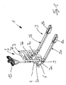
- FIG. 1 is an inventive, designed as a pallet truck pallet truck 1 with a drive part 2 and a load part 3 shown.
- the drive part 2 comprises a bow-shaped frame portion 2a, on which a drive wheel 4 having a drive unit is arranged steerable.
- the steering of the lift truck 1 is effected by means of a drawbar 15 connected to the drive wheel 4.
- the drive wheel 4 is in this case designed as a pneumatic tire drive wheel.
- For load part 3 includes two load arms 5a, 5b, with which loads, such as pallets, lattice boxes or small parts container can be added, lifted and transported.
- loads such as pallets, lattice boxes or small parts container
- a vertical strap section 7 is arranged on the load part 3, which is formed by lateral longitudinal braces 7a, 7b, a lower transverse bow 7c and an upper transverse bow 7d.
- the load part 3 is arranged on the drive part 2 by means of a lever assembly formed by articulated levers 6 movable in the vertical direction.
- a not shown hydraulic cylinder is provided, which is arranged between the drive part 2 and the load part 3 and generates a force acting on the load part 3 lifting movement.
- the load part 3 is supported by means of load rollers 8a, 8b on a roadway.
- the load rollers 8a, 8b are arranged rotatably on the load-side ends of the load arms 5a, 5b in pivotable manner on the load arms 5a, 5b, not shown load roller carriers.
- the load roller supports are in this case by means of a linkage 9 with the corresponding articulated lever 6 in operative connection, whereby a lifting movement of a hydraulic cylinder, not shown, which is disposed between the load part and the drive part, by means of the hinge lever 6 and the linkage 9 in a vertical movement of the load rollers 8a, 8b is converted and thus the load part 3 relative to the drive part 2 can be raised and lowered.
- the linkage 9 may be formed here as push rods or tie rods.
- the bow-shaped frame section 2a of the drive part 2 and the load part 3 formed by the load arms 5a, 5b and the strap section 7 are essentially formed by one-piece hollow profiles 10a, 10b, 11 with a closed cross-section.
- the frame portion 2a and the bracket portion 7 forming hollow sections 10a, 10b may be formed of tubular profiles with an annular cross-section.
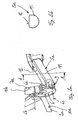
- the articulated lever 6 is mounted on the bow-shaped frame section 2a on a first articulation axis 6a on the lateral longitudinal bow 7a and on a second articulation axis 6b and is rotatably connected to the linkage 9 by means of a third articulation axis 6c.
- the load arms 5a, 5b forming hollow sections 11 are each provided at the top with a flat surface 12.
- the hollow section 11 of the load arms 5a and 5b has - as from FIG. 2b visible - in this case a substantially circular cross-section, which is provided in the upper region with a flattening, which forms the flat surface 12.
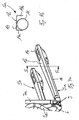
- FIGS. 3a and 3b a further embodiment of the invention is shown, wherein the load arms 5a, 5b forming hollow sections 11 each have a triangular cross-section.
- the base of the triangular cross section forms the planar surface 12 arranged on the upper side of the load arm 5a or 5b.
- the tip 13 of the triangular cross section of the hollow profiles 11 is rounded.
- the planar surface 12 is formed in each case on the hollow profile 11 forming the load arm 5a or 5b, and thus the hollow profile 11 and the flat surface 12 are integrally formed.
- the flat surface 12 is formed on a further profile element 14 which is arranged on the upper side of the load arm 5a and 5b forming the hollow section 11.
- the hollow section 11 is formed here as a tubular profile with a circular cross-section.
- the further profile element 14 is provided with a downwardly open U-shaped Cross section provided.
- the lateral limbs 14a, 14b of the further profile element 14 are in this case dimensioned such that the hollow profile 11 extends over the lateral limbs 14a, 14b of the profile element 14.
- the further profile element 14 in each case in the region of the drive part 2 has a smaller width than in the region of the load rollers 8a and 8b and thus of the load-side end, whereby the flat surface 12 at the top of the load arms 5a and 5b with increasing distance increases from the drive part 2.
- an inventive truck Due to the design of the drive part 2 and the load part 3 of hollow sections 10, 10b, 11 with a closed cross-section, an inventive truck is provided, which has a low weight and high strength and stability and thus a robust construction.
- the load rollers 8a, 8b actuated linkage 9 within the load arms 5a, 5b forming hollow sections 11 a protected from damage arrangement of the linkage 9 is achieved, in conjunction with the designed as a pneumatic drive wheel drive wheel 4 with the pallet truck according to the invention 1 obstacles can be overcome in a simple manner and the truck is suitable for applications outside of warehouses and production facilities with an uneven road surface, for example, on streets and squares.
Landscapes
- Engineering & Computer Science (AREA)
- Chemical & Material Sciences (AREA)
- Combustion & Propulsion (AREA)
- Transportation (AREA)
- Mechanical Engineering (AREA)
- Handcart (AREA)
- Forklifts And Lifting Vehicles (AREA)
Abstract
Description
Die Erfindung betrifft einen Hubwagen mit einem Antriebsteil und einem relativ zum Antriebsteil anhebbaren Lastteil, wobei der Antriebsteil mit einem mittels einer Lenkdeichsel lenkbaren Antriebrad versehen ist und der Lastteil Lastarme aufweist, an denen jeweils mindestens eine Lastrolle gelagert ist, wobei zum Anheben der Lastarme jeweils ein mit der Lastrolle in Wirkverbindung stehendes Gestänge vorgesehen ist.The invention relates to a lift truck with a drive part and a liftable relative to the drive part load part, wherein the drive part is provided with a steerable by a steering shaft drive wheel and the load part has load arms, on each of which at least one load roller is mounted, wherein for lifting the load arms each one provided with the load roller operatively connected linkage.
Derartige Hubwagen, die mittels des Antriebsrades und an den Lastarmen angeordneter Lastrollen auf einer Fahrbahn abgestützt sind, werden bevorzugt als Niederhubwagen ausgeführt. Zum Anheben des Lastteils relativ zum Antriebsteil ist ein Stellglied, beispielsweise ein Hydraulikzylinder, vorgesehen, der zwischen dem Antriebsteil und dem Lastteil, angeordnet ist. Die von dem Hydraulikzylinder auf den Lastteil ausgeübte Hubbewegung wird mittels einer Hebelanordnung in eine Horizontalbewegung der Gestänge übersetzt, welches eine Schwenkbewegung der an den Lastarmen angeordneten Lastrollenträger bewirkt, in denen die Lastrollen gelagert sind, wodurch ein Anheben der Lastarme mittels der Lastrollen erzielt wird.Such trucks, which are supported by means of the drive wheel and arranged on the load arms load rollers on a roadway, are preferably designed as low pallet truck. For lifting the load part relative to the drive part, an actuator, such as a hydraulic cylinder, is provided, which is arranged between the drive part and the load part. The force exerted by the hydraulic cylinder on the load part lifting movement is translated by a lever assembly in a horizontal movement of the linkage, which causes a pivoting movement of the load arms arranged on the load carrier, in which the load rollers are mounted, whereby a lifting of the load arms is achieved by means of load rollers.
Ein gattungsgemäßer, als Niederhubwagen ausgebildeter Hubwagen ist aus der
Bei derartigen Hubwagen kann es jedoch vorkommen, insbesondere bei angehobenen Lastarmen, dass sich das Gestänge außerhalb des Hohlprofils befindet, so dass das Gestänge beim Überfahren von Hindernissen, beispielsweise beim Überfahren von Bordsteinkanten oder Bordsteinabsenkungen an Grundstückseinfahrten, beschädigt oder verformt werden kann.In such lift trucks, however, it may happen, especially with raised load arms, that the linkage is outside the hollow profile, so that the linkage when driving over obstacles, such as when driving over curbs or curbs on land entrances, damaged or deformed.
Bei gattungsgemäßen Hubwagen kann zudem aufgrund der nach unten offenen Hohlprofile der Lastarme eine Bedienperson beim Umgreifen der Lastarme, um den Hubwagen zu transportieren oder anzuheben, einem erhöhten Verletzungsrisiko ausgesetzt sein.In generic lift truck can also be exposed to increased risk of injury due to the downwardly open hollow sections of the load arms an operator when gripping the load arms to transport or lift the pallet truck.
Der vorliegenden Erfindung liegt die Aufgabe zugrunde, einen Hubwagen der eingangs genannten Gattung zur Verfügung zu stellen, der bei leichter und robuster Bauweise eine geschützte Anordnung des Gestänges und eine einfache und sichere Handhabung durch eine Bedienperson ermöglicht.The present invention has for its object to provide a truck of the type mentioned available, which allows for a light and robust design, a protected arrangement of the linkage and a simple and safe handling by an operator.
Die Aufgabe wird erfindungsgemäß dadurch gelöst, dass der Antriebsteil und/oder der Lastteil im Wesentlichen von einstückigen Hohlprofilen mit einem geschlossenen Querschnitt gebildet ist, wobei innerhalb der die Lastarme bildenden Hohlprofile die Gestänge angeordnet sind. Der erfindungsgemäße Gedanke besteht somit darin, den Antriebsteil und den Lastteil des Hubwagens aus einstückigen Hohlprofilen zusammenzusetzen, die ein geschlossenes Profil aufweisen. Derartige Hohlprofile weisen bei einem geringen Gewicht eine hohe Steifigkeit und Festigkeit auf. Dadurch wird ein erfindungsgemäßer Hubwagen zur Verfügung gestellt, der bei geringem Eigengewicht eine robuste und stabile Bauweise aufweist. Durch die Anordnung der die Lastrollen betätigenden Gestänge innerhalb der die Lastarme bildenden Hohlprofile wird weiterhin eine vor Beschädigungen oder Verformungen beim Überfahren von Hindernissen geschützte Anordnung der Gestänge erzielt. Zudem ermöglicht die Bauweise des Antriebsteils und des Lastteils aus Hohlprofilen, die einen geschlossenen Querschnitt aufweisen, dass der Hubwagen von einer Bedienperson, insbesondere im Bereich der Lastarme des Lastteils mit der Hand sicher und mit geringer Verletzungsgefahr umgriffen werden kann, wodurch der erfindungsgemäße Hubwagen auf sichere Weise transportiert oder angehoben werden kann.The object is achieved in that the drive part and / or the load part is essentially formed of one-piece hollow sections with a closed cross section, wherein within the load arms forming hollow sections, the linkage are arranged. The idea according to the invention thus consists in assembling the drive part and the load part of the lift truck from integral hollow profiles which have a closed profile. Such hollow profiles have a high stiffness and strength at a low weight. As a result, an inventive truck is provided, which has a solid and stable construction with low weight. Due to the arrangement of the load rollers actuated linkage within the hollow arms forming the load arms, a further arrangement of the linkage protected from damage or deformation when passing over obstacles is achieved. In addition, the design of the drive part and the load part of hollow sections, which have a closed cross-section that the truck can be embraced by an operator, especially in the load arms of the load part by hand safely and with little risk of injury, causing the truck according to the invention on safe Can be transported or raised manner.
Die Hohlprofile weisen hierbei zweckmäßigerweise einen kreisförmigen Querschnitt auf. Mit derartigen Rohrprofilen wird bei geringem Eigengewicht eine hohe Stabilität und Festigkeit des Hubwagen erzielt, wobei zudem ein sicheres Umgreifen der Rohrprofile durch die Bedienperson ermöglicht wird.The hollow sections expediently have a circular cross section. With such pipe profiles a high stability and strength of the truck is achieved with low weight, in addition, a secure gripping the pipe sections is made possible by the operator.
Gemäß einer bevorzugten Ausführungsform der Erfindung sind die Lastarme an der Oberseite jeweils mit einer ebenen Fläche versehen. Hierdurch kann auf einfache Weise an der Oberseite der Lastarme eine ebene Auflagefläche für eine Last, beispielsweise eine Palette, eine Gitterbox oder einen Kleinteilebehälter, und somit ein sicherer Transport der Last erzielt werden.According to a preferred embodiment of the invention, the load arms are each provided on the upper side with a flat surface. This can be done on simple Way at the top of the load arms a flat support surface for a load, such as a pallet, a mesh box or a small parts container, and thus a secure transport of the load can be achieved.
Hinsichtlich eines geringen Bauaufwands ist es vorteilhaft, wenn gemäß einer Ausgestaltungsform der Erfindung die die Lastarme bildenden Hohlprofile an der Oberseite jeweils mit einer ebenen Fläche versehen sind und somit die ebene Fläche einstückig an den die Lastarme bildenden Hohlprofilen angeformt ist.With regard to a low construction cost, it is advantageous if, according to an embodiment of the invention, the hollow arms forming the load arms are provided at the top with a flat surface and thus the flat surface is integrally formed on the hollow profiles forming the load arms.
Gegenüber dieser einstückigen Bauweise kann gemäß einer weiteren Ausgestaltungsform der Erfindung an der Oberseite der die Lastarme bildenden Hohlprofile jeweils ein mit einer ebenen Fläche versehenes, weiteres Profilelement angeordnet sein. Durch das weitere Profilelement kann bei Hohlprofilen, die einen kreisförmigen Querschnitt aufweisen und die Lastarme bilden, mit geringem zusätzlichen Bauaufwand die ebene Fläche an der Oberseite der Lastarme für einen sicheren Transport der aufgenommenen Last erzeugt werden. Zudem ist durch das weitere Profilelement eine weitere Stabilitätserhöhung der Lastarme, insbesondere eine erhöhte Verwindungssteifigkeit der Lastarme, mit geringem Bauaufwand erzielbar.Compared to this one-piece design can be arranged according to a further embodiment of the invention at the top of the load arms forming hollow profiles each provided with a flat surface, another profile element. Due to the further profile element can be produced at low additional construction cost, the flat surface at the top of the load arms for secure transport of the recorded load in hollow sections, which have a circular cross-section and the load arms. In addition, a further increase in stability of the load arms, in particular an increased torsional stiffness of the load arms, can be achieved with little construction effort by the further profile element.
Das weitere Profilelement weist vorteilhafterweise einen nach unten offenen U-förmigen Querschnitt auf, wobei sich das den Lastarm bildende Hohlprofil über die seitliche Schenkel des Profilelements erstreckt. Hierdurch kann mittels des weiteren Profilelements auf einfache Weise die ebene Fläche und eine stabilitätserhöhende Wirkung an den Lastarmen erzielt werden, wobei dadurch, dass sich das Hohlprofil über die seitlichen Schenkel des weiteren Profilelements erstreckt, scharfe Kanten beim Umgreifen des von dem Hohlprofil und dem Profilelement gebildeten Lastarms wirksam vermieden werden.The further profile element advantageously has a downwardly open U-shaped cross-section, wherein the hollow section forming the load arm extends over the lateral limbs of the profile element. As a result, the planar surface and a stability-increasing effect on the load arms can be achieved in a simple manner by means of the further profile element, wherein the fact that the hollow profile extends over the lateral legs of the further profile element, sharp edges when gripping the formed by the hollow profile and the profile element Lastarms be effectively avoided.
Weitere Vorteile sind erzielbar, wenn das weitere Profilelement im Bereich des antriebsteilseitigen Endes des Lastarmes eine geringere Breite als im Bereich des lastteilseitigen Endes des Lastarmes aufweist. Hierdurch wird auf einfache Weise die Verwindungssteifigkeit der Lastarme erhöht und zudem erzielt, dass am lastteilseitigen Ende der Lastarme im Bereich der Lastrollen eine große Aufstandsfläche für die Last zur Verfügung steht, um beispielsweise bei einer lediglich an den Spitzen der Lastarme teilsweise aufgenommenen Last ein Ziehen oder Schieben der von einer Palette, einer Gitterbox oder einem Kleinteilebehälter gebildeten Last zu ermöglichen.Further advantages can be achieved if the further profile element in the region of the drive part-side end of the load arm has a smaller width than in the region of the load-part-side end of the load arm. As a result, the torsional stiffness of the load arms is increased in a simple manner and also achieved that the load-side end of the load arms in the load rollers a large footprint for the load is available, for example, only at the tips of the load arms partially loaded load to allow pulling or pushing the load formed by a pallet, a grid box or a small parts container.
Bei einer einstückigen Ausbildung der die Lastarme bildenden Hohlprofile mit der ebenen Fläche an der Oberseite der Lastarme können die die Lastarme bildenden Hohlprofile gemäß einer Ausgestaltungsform der Erfindung von jeweils einem Hohlprofil mit einem im wesentlichen kreisförmigen Querschnitt gebildet sein, der an der Oberseite mit einer ebenen Fläche versehen ist. Ein derartiges, an der Oberseite abgeplattetes Rohrprofil ist auf einfache Weise herstellbar und weist unter Bildung einer ebenen Fläche für die Lastaufnahme eine hohe Stabilität und Festigkeit auf.In a one-piece design of the load arms forming hollow sections with the flat surface at the top of the load arms forming the load arms hollow profiles may be formed according to an embodiment of the invention by a respective hollow profile having a substantially circular cross section, which at the top with a flat surface is provided. Such a flattened at the top tube profile can be produced in a simple manner and has a high stability and strength to form a flat surface for the load bearing.
Gemäß einer weiteren Ausgestaltungsform der Erfindung können die die Lastarme bildenden Hohlprofile jeweils einen dreieckförmigen Querschnitt aufweisen, wobei die Basis des dreieckförmigen Querschnitts die an der Oberseite des Lastarmes angeordnete ebene Fläche bildet und die Spitze des dreieckförmigen Querschnitts abgerundet ist. Hierdurch wird ebenfalls auf einfache Weise ein Hohlprofil mit einer hohen Stabilität und Festigkeit zur Verfügung gestellt, das eine ebene Fläche für die Lastaufnahme aufweist, wobei aufgrund der abgerundeten Spitze eine sichere Handhabung und ein sicheres Umgreifen durch die Bedienperson ermöglicht wird.According to a further embodiment of the invention, the hollow arms forming the load arms can each have a triangular cross section, wherein the base of the triangular cross section forms the flat surface arranged on the upper side of the load arm and the tip of the triangular cross section is rounded. As a result, a hollow profile with a high stability and strength is also provided in a simple manner, which has a flat surface for the load-bearing, which due to the rounded tip safe handling and safe grasping is made possible by the operator.
Besondere Vorteile ergeben sich, wenn an den den Lastarmen bildenden Hohlprofilen an dem dem Antriebsteil zugewandten Bereich ein von einstückigen, geschlossenen Hohlprofilen gebildeter Bügelabschnitt angeordnet ist. Hierdurch kann mit geringem Bauaufwand und mit geringem Eigengewicht eine Abgrenzung zwischen dem Lastteil und dem Antriebsteil erzielt werden, wobei an diesem Bügelabschnitt auf einfache Weise weitere Aggregate, beispielsweise eine Batterie für ein batterie-elektrisches Antriebssystem des Hubwagens angeordnet werden kann.Particular advantages arise when arranged on the load arms forming hollow profiles on the drive part facing region of a one-piece, closed hollow sections formed strap section. As a result, a demarcation between the load part and the drive part can be achieved with little construction effort and low weight, with further units, such as a battery for a battery-electric drive system of the lift truck can be arranged on this bracket section in a simple manner.
Zweckmäßigerweise bilden die den Antriebsteil bildenden Hohlprofile einen bügelförmigen Rahmenabschnitt zur Aufnahme des Antriebsrades. Ein derartiges, von einem bügelförmigen Rahmenabschnitt gebildetes Antriebsteil weist bei geringem Eigengewicht eine hohe Stabilität und Festigkeit auf und kann auf einfache Weise von Hohlprofilen gebildet werden.Expediently, the hollow sections forming the drive part form a bow-shaped frame section for receiving the drive wheel. Such, formed by a bow-shaped frame portion drive part has a low weight on a high stability and strength and can be easily formed by hollow sections.
Zweckmäßigerweise ist das Antriebsrad als luftbereiftes Antriebsrad ausgebildet. Hierdurch ist der erfindungsgemäße Hubwagen für Anwendungen außerhalb von Lagerhallen und Produktionsbetrieben geeignet bei denen eine unebene Fahrbahnoberfläche gegeben ist, beispielsweise auf Straßen und Plätzen, wodurch aufgrund des als luftbereiften Antriebsrades ausgebildeten Antriebsrades mit dem erfindungsgemäßen Hubwagen Hindernisse, beispielsweise Bordsteinkanten und Bordsteinabsenkungen, auf einfache Weise überwunden werden können.Conveniently, the drive wheel is designed as a pneumatic tire drive wheel. As a result, the pallet truck according to the invention for applications outside of warehouses and production facilities is suitable in which an uneven road surface is given, for example, on streets and squares, which overcome obstacles due to the drive wheel designed as tire drive wheel with the truck according to the invention obstacles, such as curbs and curbs, in a simple manner can be.
Weitere Vorteile und Einzelheiten der Erfindung werden anhand der in den schematischen Figuren dargestellten Ausführungsbeispiele näher erläutert. Hierbei zeigt
Figur 1- einen erfindungsgemäßen Hubwagen in einer perspektivischen Darstellung,
- Figur 2a
- eine perspektivische Darstellung eines Lastarmes einer ersten Ausführungsform eines erfindungsgemäßen Hubwagens,
- Figur 2b
- einen Schnitt entlang der Linie A-A in
Figur 2a , - Figur 3a
- eine perspektivische Darstellung eines Lastarmes gemäß der
Figur 2a in einer zweiten Ausführungsform eines erfindungsgemäßen Hubwagens - Figur 3b
- einen Schnitt entlang der Linie B-B in
Figur 3a , - Figur 4a
- eine perspektivische Darstellung eines Lastarmes gemäß der
Figur 2a einer dritten Ausführungsform eines erfindungsgemäßen Hubwagens, - Figur 4b
- einen Schnitt entlang der Linie C-C in
Figur 4a und - Figur 5
- eine Draufsicht auf die Lastarme eine Hubwagens gemäß den
Figuren 4a, 4b .
- FIG. 1
- a lifting truck according to the invention in a perspective view,
- FIG. 2a
- a perspective view of a load arm of a first embodiment of a lift truck according to the invention,
- FIG. 2b
- a section along the line AA in
FIG. 2a . - FIG. 3a
- a perspective view of a load arm according to the
FIG. 2a in a second embodiment of a lift truck according to the invention - FIG. 3b
- a section along the line BB in
FIG. 3a . - FIG. 4a
- a perspective view of a load arm according to the
FIG. 2a a third embodiment of a lift truck according to the invention, - FIG. 4b
- a section along the line CC in
FIG. 4a and - FIG. 5
- a plan view of the load arms of a lift truck according to the
FIGS. 4a, 4b ,
In der
Zum Lastteil 3 gehören zwei Lastarme 5a, 5b, mit denen Lasten, beispielsweise Paletten, Gitterboxen oder Kleinteilebehälter aufgenommen, angehoben und transportiert werden können. An dem dem Antriebsteil 2 zugewandten Bereich des Lastteils 3 ist am Lastteil 3 ein vertikaler Bügelabschnitt 7 angeordnet, der von seitlichen Längsbügeln 7a, 7b, einem unteren Querbügel 7c und einem oberen Querbügel 7d gebildet ist.For
Der Lastteil 3 ist an dem Antriebsteil 2 mittels einer von Gelenkhebeln 6 gebildeten Hebelanordnung in vertikaler Richtung bewegbar angeordnet. Hierzu ist ein nicht mehr dargestellter Hydraulikzylinder vorgesehen, der zwischen dem Antriebsteil 2 und dem Lastteil 3 angeordnet ist und eine auf den Lastteil 3 wirkende Hubbewegung erzeugt.The
Der Lastteil 3 stützt sich mittels Lastrollen 8a, 8b auf einer Fahrbahn ab. Die Lastrollen 8a, 8b sind an den lastseitigen Enden der Lastarme 5a, 5b in schwenkbar an den Lastarmen 5a, 5b angeordneten, nicht mehr dargestellten Lastrollenträgern drehbar angeordnet. Die Lastrollenträger stehen hierbei mittels jeweils eines Gestänges 9 mit dem entsprechenden Gelenkhebel 6 in Wirkverbindung, wodurch eine Hubbewegung eines nicht mehr dargestellten Hydraulikzylinders, der zwischen dem Lastteil und dem Antriebsteil angeordnet ist, mittels der Gelenkhebel 6 und der Gestänge 9 in eine vertikale Bewegung der Lastrollen 8a, 8b umgewandelt wird und somit der Lastteil 3 relativ zum Antriebsteil 2 anhebbar und absenkbar ist. Die Gestänge 9 können hierbei als Druckstangen oder Zugstangen ausgebildet sein.The
Erfindungsgemäß ist der bügelförmige Rahmenabschnitt 2a des Antriebsteils 2 und der von den Lastarmen 5a, 5b sowie dem Bügelabschnitt 7 gebildete Lastteil 3 im Wesentlichen von einstückigen Hohlprofilen 10a, 10b, 11 mit einem geschlossenen Querschnitt gebildet.According to the invention, the bow-shaped frame section 2a of the drive part 2 and the
Wie aus der
Innerhalb der die Lastarme 5a bzw. 5b bildenden Hohlprofile 11 ist jeweils das mit dem Gelenkhebel 6 und dem Lastrollenträger in Wirkverbindung stehende Gestänge 9 angeordnet.Within the load arms 5a and 5b forming
Der Gelenkhebel 6 ist hierbei an einer ersten Gelenkachse 6a an dem seitlichen Längsbügel 7a und an einer zweiten Gelenkachse 6b an dem bügelförmigen Rahmenabschnitt 2a gelagert und steht mittels einer dritten Gelenkachse 6c drehbar mit dem Gestänge 9 in Verbindung.The articulated
Die die Lastarme 5a, 5b bildenden Hohlprofile 11 sind jeweils an der Oberseite mit einer ebenen Fläche 12 versehen. Das Hohlprofil 11 der Lastarme 5a bzw. 5b weist - wie aus der
In den
Gemäß den
Bei der in den
Wie aus der
Aufgrund der Bauweise des Antriebsteils 2 sowie des Lastteils 3 aus Hohlprofilen 10, 10b, 11 mit einem geschlossenen Querschnitt wird ein erfindungsgemäßer Hubwagen zur Verfügung gestellt, der bei geringem Eigengewicht eine hohe Festigkeit und Stabilität und somit eine robuste Bauweise aufweist. Durch die Anordnung der die Lastrollen 8a, 8b betätigenden Gestänge 9 innerhalb der die Lastarme 5a, 5b bildenden Hohlprofile 11 wird eine vor Beschädigungen geschützte Anordnung der Gestänge 9 erzielt, wobei in Verbindung mit dem als luftbereiften Antriebsrad ausgebildeten Antriebsrad 4 mit dem erfindungsgemäßen Hubwagen 1 Hindernisse auf einfache Weise überwunden werden können und der Hubwagen für Anwendungen außerhalb von Lagerhallen und Produktionsbetrieben mit einer unebenen Fahrbahnoberfläche, beispielsweise auf Straßen und Plätzen geeignet ist. Durch die leichte Bauweise des erfindungsgemäßen Hubwagens 1 und die Verwendung von geschlossenen Hohlprofilen 10a, 10b, 11 kann zudem eine Bedienperson den erfindungsgemäßen Hubwagen 1 an den Hohlprofilen 10a, 10b, 11 sicher umgreifen, um den erfindungsgemäßen Hubwagen 1 zum Transport auf ein Transportfahrzeug anzuheben und zu verladen.Due to the design of the drive part 2 and the
Claims (12)
Applications Claiming Priority (1)
| Application Number | Priority Date | Filing Date | Title |
|---|---|---|---|
| DE200710034745 DE102007034745A1 (en) | 2007-07-25 | 2007-07-25 | lift trucks |
Publications (3)
| Publication Number | Publication Date |
|---|---|
| EP2019014A2 true EP2019014A2 (en) | 2009-01-28 |
| EP2019014A3 EP2019014A3 (en) | 2010-09-01 |
| EP2019014B1 EP2019014B1 (en) | 2016-12-07 |
Family
ID=40029018
Family Applications (1)
| Application Number | Title | Priority Date | Filing Date |
|---|---|---|---|
| EP08009398.2A Not-in-force EP2019014B1 (en) | 2007-07-25 | 2008-05-21 | Jack lift |
Country Status (3)
| Country | Link |
|---|---|
| EP (1) | EP2019014B1 (en) |
| JP (1) | JP5348959B2 (en) |
| DE (1) | DE102007034745A1 (en) |
Cited By (2)
| Publication number | Priority date | Publication date | Assignee | Title |
|---|---|---|---|---|
| NL2009088C2 (en) * | 2012-06-29 | 2013-12-31 | Ravas Europ B V | FORKLIFT. |
| WO2020043912A3 (en) * | 2018-08-30 | 2020-05-14 | Deckel Maho Pfronten Gmbh | Transport device for transporting one or more handling devices |
Families Citing this family (1)
| Publication number | Priority date | Publication date | Assignee | Title |
|---|---|---|---|---|
| DE102007035268A1 (en) * | 2007-07-27 | 2009-01-29 | Linde Material Handling Gmbh | Warehousing vehicle, in particular low-lift trucks |
Citations (4)
| Publication number | Priority date | Publication date | Assignee | Title |
|---|---|---|---|---|
| US2940767A (en) | 1955-10-04 | 1960-06-14 | Yale & Towne Mfg Co | Light duty hydraulic truck |
| US4027771A (en) | 1975-05-08 | 1977-06-07 | Adams Thomas F | Pallet truck for use with fork lift truck |
| DE4209863A1 (en) | 1992-03-26 | 1993-09-30 | Linde Ag | Pallet truck |
| DE19934993A1 (en) | 1999-07-26 | 2001-02-08 | Jungheinrich Ag | Wheel arms for low-lift fork truck has closed box construction, with tapered end formed by pressing, and front end of end section is open for insertion of pre-assembled unit comprising pressure rod, swinging arm and running wheel |
Family Cites Families (8)
| Publication number | Priority date | Publication date | Assignee | Title |
|---|---|---|---|---|
| GB804092A (en) * | 1954-02-15 | 1958-11-05 | Einar Danielsen | Improvements in or relating to transport platforms or skids |
| GB1005291A (en) * | 1963-01-31 | 1965-09-22 | Lansing Bagnall Ltd | Improvements in or relating to pallet trucks |
| JPS58173572U (en) * | 1982-05-18 | 1983-11-19 | 佐藤 政太郎 | Loader for pallet handling |
| JPH0381179U (en) * | 1989-12-08 | 1991-08-20 | ||
| US20070116548A1 (en) * | 2005-11-18 | 2007-05-24 | Cooper David A | Fork-type pallet-lifting device |
| JP2008043507A (en) * | 2006-08-15 | 2008-02-28 | Smk:Kk | Ball box lifting device |
| DE102007034743A1 (en) * | 2007-07-25 | 2009-01-29 | Linde Material Handling Gmbh | Pallet truck with a battery compartment and a battery |
| DE102007035268A1 (en) * | 2007-07-27 | 2009-01-29 | Linde Material Handling Gmbh | Warehousing vehicle, in particular low-lift trucks |
-
2007
- 2007-07-25 DE DE200710034745 patent/DE102007034745A1/en not_active Withdrawn
-
2008
- 2008-05-21 EP EP08009398.2A patent/EP2019014B1/en not_active Not-in-force
- 2008-07-24 JP JP2008190686A patent/JP5348959B2/en not_active Expired - Fee Related
Patent Citations (4)
| Publication number | Priority date | Publication date | Assignee | Title |
|---|---|---|---|---|
| US2940767A (en) | 1955-10-04 | 1960-06-14 | Yale & Towne Mfg Co | Light duty hydraulic truck |
| US4027771A (en) | 1975-05-08 | 1977-06-07 | Adams Thomas F | Pallet truck for use with fork lift truck |
| DE4209863A1 (en) | 1992-03-26 | 1993-09-30 | Linde Ag | Pallet truck |
| DE19934993A1 (en) | 1999-07-26 | 2001-02-08 | Jungheinrich Ag | Wheel arms for low-lift fork truck has closed box construction, with tapered end formed by pressing, and front end of end section is open for insertion of pre-assembled unit comprising pressure rod, swinging arm and running wheel |
Cited By (9)
| Publication number | Priority date | Publication date | Assignee | Title |
|---|---|---|---|---|
| NL2009088C2 (en) * | 2012-06-29 | 2013-12-31 | Ravas Europ B V | FORKLIFT. |
| WO2014003569A1 (en) * | 2012-06-29 | 2014-01-03 | Ravas Europe B.V. | Lift truck |
| WO2020043912A3 (en) * | 2018-08-30 | 2020-05-14 | Deckel Maho Pfronten Gmbh | Transport device for transporting one or more handling devices |
| WO2020043915A3 (en) * | 2018-08-30 | 2020-07-23 | Deckel Maho Pfronten Gmbh | Transport device for receiving one or more module units having machine tool accessory devices and for transporting the one or more received module units |
| CN112789138A (en) * | 2018-08-30 | 2021-05-11 | 德克尔马霍普夫龙滕有限公司 | Transport device for receiving one or more modular units with machine tool accessory devices and for transporting the one or more received modular units |
| EP3746262B1 (en) | 2018-08-30 | 2021-06-30 | DECKEL MAHO Pfronten GmbH | Transport device for transporting one or more handling devices |
| US20210346998A1 (en) * | 2018-08-30 | 2021-11-11 | Deckel Maho Pfronten Gmbh | Transport Device for Receiving one or more Module Units Having Machine Tool Accessory Devices and for Transporting the one or more Received Module Units |
| US11938583B2 (en) * | 2018-08-30 | 2024-03-26 | Deckel Maho Pfronten Gmbh | Transport device for receiving one or more module units having machine tool accessory devices and for transporting the one or more received module units |
| US12251784B2 (en) | 2018-08-30 | 2025-03-18 | Deckel Maho Pfronten Gmbh | Transport device for transporting one or more handling devices |
Also Published As
| Publication number | Publication date |
|---|---|
| JP2009029412A (en) | 2009-02-12 |
| JP5348959B2 (en) | 2013-11-20 |
| EP2019014A3 (en) | 2010-09-01 |
| DE102007034745A1 (en) | 2009-01-29 |
| EP2019014B1 (en) | 2016-12-07 |
Similar Documents
| Publication | Publication Date | Title |
|---|---|---|
| EP2910416B1 (en) | Trailer for a route train | |
| DE102014100865B4 (en) | Tugger train trailer with a chassis and a transport device | |
| DE2654286A1 (en) | LOADING DEVICE FOR TRUCK BODIES | |
| EP2719603A1 (en) | Industrial truck with load rollers arranged in load roller mounts on a wheel arm | |
| EP0808747A1 (en) | Loading tailgate system | |
| EP2020358B1 (en) | Jack lift with lift arm | |
| EP2719601B1 (en) | Industrial truck, in particular jack lift | |
| DE2944289A1 (en) | LIFTING VEHICLE | |
| EP2019014B1 (en) | Jack lift | |
| DE202018101228U1 (en) | Palettenhubanhänger | |
| EP2969890B1 (en) | Mast assembly for an industrial truck | |
| EP2719602B1 (en) | Industrial truck with load rollers arranged in load roller mounts on a wheel arm | |
| EP1690823B1 (en) | Industrial truck | |
| DE102008063593A1 (en) | Pallet truck, in particular pallet truck | |
| DE102009059949A1 (en) | Ground conveyor has lifting device, which is arranged on each of wheel arms and cooperates with wheel arm lever, where drive part is tilted over its drive wheel | |
| DE102016107538A1 (en) | Truck with a pair of height-adjustable fork arms | |
| EP1077169B1 (en) | Industrial truck with supporting wheels | |
| EP1106431B1 (en) | Loading tailgate system | |
| DE102009004403A1 (en) | Ground conveyor, particularly hand lift, has drive component and load component which is vertically movable relative to drive component, where load component has load arms which are supported by load roller unit having load roller | |
| DE102008049072A1 (en) | Ground conveyor i.e. high elevating platform truck, has force-transmitting linkage device for operating carrier, and cam roller arranged at linkage device in longitudinal direction of ground conveyor spaced at distance to load roller | |
| EP3819167B1 (en) | Load lifting device | |
| DE102010010747A1 (en) | Pallet for a storage system | |
| DE102009004405A1 (en) | Industrial truck i.e. freight forwarder, has coupling shaft provided with deflection lever between level arms, where deflection lever is operatively connected with lifting path, where level arms are hinged at outer regions of coupling shaft | |
| DE202009002125U1 (en) | Construction of a transport vehicle | |
| EP1688300B1 (en) | Device for loading and unloading a platform |
Legal Events
| Date | Code | Title | Description |
|---|---|---|---|
| PUAI | Public reference made under article 153(3) epc to a published international application that has entered the european phase |
Free format text: ORIGINAL CODE: 0009012 |
|
| AK | Designated contracting states |
Kind code of ref document: A2 Designated state(s): AT BE BG CH CY CZ DE DK EE ES FI FR GB GR HR HU IE IS IT LI LT LU LV MC MT NL NO PL PT RO SE SI SK TR |
|
| AX | Request for extension of the european patent |
Extension state: AL BA MK RS |
|
| PUAL | Search report despatched |
Free format text: ORIGINAL CODE: 0009013 |
|
| AK | Designated contracting states |
Kind code of ref document: A3 Designated state(s): AT BE BG CH CY CZ DE DK EE ES FI FR GB GR HR HU IE IS IT LI LT LU LV MC MT NL NO PL PT RO SE SI SK TR |
|
| AX | Request for extension of the european patent |
Extension state: AL BA MK RS |
|
| 17P | Request for examination filed |
Effective date: 20110301 |
|
| AKX | Designation fees paid |
Designated state(s): AT BE BG CH CY CZ DE DK EE ES FI FR GB GR HR HU IE IS IT LI LT LU LV MC MT NL NO PL PT RO SE SI SK TR |
|
| 17Q | First examination report despatched |
Effective date: 20150918 |
|
| RAP1 | Party data changed (applicant data changed or rights of an application transferred) |
Owner name: LINDE MATERIAL HANDLING GMBH |
|
| GRAP | Despatch of communication of intention to grant a patent |
Free format text: ORIGINAL CODE: EPIDOSNIGR1 |
|
| INTG | Intention to grant announced |
Effective date: 20160708 |
|
| GRAS | Grant fee paid |
Free format text: ORIGINAL CODE: EPIDOSNIGR3 |
|
| STAA | Information on the status of an ep patent application or granted ep patent |
Free format text: STATUS: GRANT OF PATENT IS INTENDED |
|
| GRAA | (expected) grant |
Free format text: ORIGINAL CODE: 0009210 |
|
| STAA | Information on the status of an ep patent application or granted ep patent |
Free format text: STATUS: THE PATENT HAS BEEN GRANTED |
|
| AK | Designated contracting states |
Kind code of ref document: B1 Designated state(s): AT BE BG CH CY CZ DE DK EE ES FI FR GB GR HR HU IE IS IT LI LT LU LV MC MT NL NO PL PT RO SE SI SK TR |
|
| REG | Reference to a national code |
Ref country code: GB Ref legal event code: FG4D Free format text: NOT ENGLISH |
|
| REG | Reference to a national code |
Ref country code: CH Ref legal event code: EP Ref country code: AT Ref legal event code: REF Ref document number: 851408 Country of ref document: AT Kind code of ref document: T Effective date: 20161215 |
|
| REG | Reference to a national code |
Ref country code: IE Ref legal event code: FG4D Free format text: LANGUAGE OF EP DOCUMENT: GERMAN |
|
| REG | Reference to a national code |
Ref country code: DE Ref legal event code: R082 Ref document number: 502008014858 Country of ref document: DE Representative=s name: PATENTSHIP PATENTANWALTSGESELLSCHAFT MBH, DE |
|
| REG | Reference to a national code |
Ref country code: DE Ref legal event code: R096 Ref document number: 502008014858 Country of ref document: DE |
|
| REG | Reference to a national code |
Ref country code: DE Ref legal event code: R082 Ref document number: 502008014858 Country of ref document: DE Representative=s name: PATENTSHIP PATENTANWALTSGESELLSCHAFT MBH, DE |
|
| PG25 | Lapsed in a contracting state [announced via postgrant information from national office to epo] |
Ref country code: LV Free format text: LAPSE BECAUSE OF FAILURE TO SUBMIT A TRANSLATION OF THE DESCRIPTION OR TO PAY THE FEE WITHIN THE PRESCRIBED TIME-LIMIT Effective date: 20161207 |
|
| REG | Reference to a national code |
Ref country code: LT Ref legal event code: MG4D |
|
| REG | Reference to a national code |
Ref country code: NL Ref legal event code: MP Effective date: 20161207 |
|
| PG25 | Lapsed in a contracting state [announced via postgrant information from national office to epo] |
Ref country code: SE Free format text: LAPSE BECAUSE OF FAILURE TO SUBMIT A TRANSLATION OF THE DESCRIPTION OR TO PAY THE FEE WITHIN THE PRESCRIBED TIME-LIMIT Effective date: 20161207 Ref country code: GR Free format text: LAPSE BECAUSE OF FAILURE TO SUBMIT A TRANSLATION OF THE DESCRIPTION OR TO PAY THE FEE WITHIN THE PRESCRIBED TIME-LIMIT Effective date: 20170308 Ref country code: LT Free format text: LAPSE BECAUSE OF FAILURE TO SUBMIT A TRANSLATION OF THE DESCRIPTION OR TO PAY THE FEE WITHIN THE PRESCRIBED TIME-LIMIT Effective date: 20161207 Ref country code: NO Free format text: LAPSE BECAUSE OF FAILURE TO SUBMIT A TRANSLATION OF THE DESCRIPTION OR TO PAY THE FEE WITHIN THE PRESCRIBED TIME-LIMIT Effective date: 20170307 |
|
| REG | Reference to a national code |
Ref country code: FR Ref legal event code: PLFP Year of fee payment: 10 |
|
| PG25 | Lapsed in a contracting state [announced via postgrant information from national office to epo] |
Ref country code: ES Free format text: LAPSE BECAUSE OF FAILURE TO SUBMIT A TRANSLATION OF THE DESCRIPTION OR TO PAY THE FEE WITHIN THE PRESCRIBED TIME-LIMIT Effective date: 20161207 Ref country code: HR Free format text: LAPSE BECAUSE OF FAILURE TO SUBMIT A TRANSLATION OF THE DESCRIPTION OR TO PAY THE FEE WITHIN THE PRESCRIBED TIME-LIMIT Effective date: 20161207 Ref country code: FI Free format text: LAPSE BECAUSE OF FAILURE TO SUBMIT A TRANSLATION OF THE DESCRIPTION OR TO PAY THE FEE WITHIN THE PRESCRIBED TIME-LIMIT Effective date: 20161207 |
|
| PG25 | Lapsed in a contracting state [announced via postgrant information from national office to epo] |
Ref country code: NL Free format text: LAPSE BECAUSE OF FAILURE TO SUBMIT A TRANSLATION OF THE DESCRIPTION OR TO PAY THE FEE WITHIN THE PRESCRIBED TIME-LIMIT Effective date: 20161207 |
|
| PG25 | Lapsed in a contracting state [announced via postgrant information from national office to epo] |
Ref country code: RO Free format text: LAPSE BECAUSE OF FAILURE TO SUBMIT A TRANSLATION OF THE DESCRIPTION OR TO PAY THE FEE WITHIN THE PRESCRIBED TIME-LIMIT Effective date: 20161207 Ref country code: CZ Free format text: LAPSE BECAUSE OF FAILURE TO SUBMIT A TRANSLATION OF THE DESCRIPTION OR TO PAY THE FEE WITHIN THE PRESCRIBED TIME-LIMIT Effective date: 20161207 Ref country code: IS Free format text: LAPSE BECAUSE OF FAILURE TO SUBMIT A TRANSLATION OF THE DESCRIPTION OR TO PAY THE FEE WITHIN THE PRESCRIBED TIME-LIMIT Effective date: 20170407 Ref country code: SK Free format text: LAPSE BECAUSE OF FAILURE TO SUBMIT A TRANSLATION OF THE DESCRIPTION OR TO PAY THE FEE WITHIN THE PRESCRIBED TIME-LIMIT Effective date: 20161207 Ref country code: EE Free format text: LAPSE BECAUSE OF FAILURE TO SUBMIT A TRANSLATION OF THE DESCRIPTION OR TO PAY THE FEE WITHIN THE PRESCRIBED TIME-LIMIT Effective date: 20161207 |
|
| PG25 | Lapsed in a contracting state [announced via postgrant information from national office to epo] |
Ref country code: BG Free format text: LAPSE BECAUSE OF FAILURE TO SUBMIT A TRANSLATION OF THE DESCRIPTION OR TO PAY THE FEE WITHIN THE PRESCRIBED TIME-LIMIT Effective date: 20170307 Ref country code: PT Free format text: LAPSE BECAUSE OF FAILURE TO SUBMIT A TRANSLATION OF THE DESCRIPTION OR TO PAY THE FEE WITHIN THE PRESCRIBED TIME-LIMIT Effective date: 20170407 Ref country code: IT Free format text: LAPSE BECAUSE OF FAILURE TO SUBMIT A TRANSLATION OF THE DESCRIPTION OR TO PAY THE FEE WITHIN THE PRESCRIBED TIME-LIMIT Effective date: 20161207 Ref country code: PL Free format text: LAPSE BECAUSE OF FAILURE TO SUBMIT A TRANSLATION OF THE DESCRIPTION OR TO PAY THE FEE WITHIN THE PRESCRIBED TIME-LIMIT Effective date: 20161207 Ref country code: LU Free format text: LAPSE BECAUSE OF NON-PAYMENT OF DUE FEES Effective date: 20170531 |
|
| REG | Reference to a national code |
Ref country code: DE Ref legal event code: R097 Ref document number: 502008014858 Country of ref document: DE |
|
| PLBE | No opposition filed within time limit |
Free format text: ORIGINAL CODE: 0009261 |
|
| STAA | Information on the status of an ep patent application or granted ep patent |
Free format text: STATUS: NO OPPOSITION FILED WITHIN TIME LIMIT |
|
| 26N | No opposition filed |
Effective date: 20170908 |
|
| PG25 | Lapsed in a contracting state [announced via postgrant information from national office to epo] |
Ref country code: SI Free format text: LAPSE BECAUSE OF FAILURE TO SUBMIT A TRANSLATION OF THE DESCRIPTION OR TO PAY THE FEE WITHIN THE PRESCRIBED TIME-LIMIT Effective date: 20161207 Ref country code: DK Free format text: LAPSE BECAUSE OF FAILURE TO SUBMIT A TRANSLATION OF THE DESCRIPTION OR TO PAY THE FEE WITHIN THE PRESCRIBED TIME-LIMIT Effective date: 20161207 |
|
| REG | Reference to a national code |
Ref country code: CH Ref legal event code: PL |
|
| PG25 | Lapsed in a contracting state [announced via postgrant information from national office to epo] |
Ref country code: MC Free format text: LAPSE BECAUSE OF FAILURE TO SUBMIT A TRANSLATION OF THE DESCRIPTION OR TO PAY THE FEE WITHIN THE PRESCRIBED TIME-LIMIT Effective date: 20161207 |
|
| REG | Reference to a national code |
Ref country code: IE Ref legal event code: MM4A |
|
| PG25 | Lapsed in a contracting state [announced via postgrant information from national office to epo] |
Ref country code: LI Free format text: LAPSE BECAUSE OF NON-PAYMENT OF DUE FEES Effective date: 20170531 Ref country code: CH Free format text: LAPSE BECAUSE OF NON-PAYMENT OF DUE FEES Effective date: 20170531 |
|
| PG25 | Lapsed in a contracting state [announced via postgrant information from national office to epo] |
Ref country code: LU Free format text: LAPSE BECAUSE OF NON-PAYMENT OF DUE FEES Effective date: 20170521 |
|
| REG | Reference to a national code |
Ref country code: BE Ref legal event code: MM Effective date: 20170531 |
|
| PG25 | Lapsed in a contracting state [announced via postgrant information from national office to epo] |
Ref country code: IE Free format text: LAPSE BECAUSE OF NON-PAYMENT OF DUE FEES Effective date: 20170521 |
|
| REG | Reference to a national code |
Ref country code: FR Ref legal event code: PLFP Year of fee payment: 11 |
|
| REG | Reference to a national code |
Ref country code: AT Ref legal event code: MM01 Ref document number: 851408 Country of ref document: AT Kind code of ref document: T Effective date: 20170521 |
|
| PG25 | Lapsed in a contracting state [announced via postgrant information from national office to epo] |
Ref country code: BE Free format text: LAPSE BECAUSE OF NON-PAYMENT OF DUE FEES Effective date: 20170531 Ref country code: AT Free format text: LAPSE BECAUSE OF NON-PAYMENT OF DUE FEES Effective date: 20170521 |
|
| PG25 | Lapsed in a contracting state [announced via postgrant information from national office to epo] |
Ref country code: MT Free format text: LAPSE BECAUSE OF FAILURE TO SUBMIT A TRANSLATION OF THE DESCRIPTION OR TO PAY THE FEE WITHIN THE PRESCRIBED TIME-LIMIT Effective date: 20161207 |
|
| PG25 | Lapsed in a contracting state [announced via postgrant information from national office to epo] |
Ref country code: HU Free format text: LAPSE BECAUSE OF FAILURE TO SUBMIT A TRANSLATION OF THE DESCRIPTION OR TO PAY THE FEE WITHIN THE PRESCRIBED TIME-LIMIT; INVALID AB INITIO Effective date: 20080521 |
|
| PG25 | Lapsed in a contracting state [announced via postgrant information from national office to epo] |
Ref country code: CY Free format text: LAPSE BECAUSE OF NON-PAYMENT OF DUE FEES Effective date: 20161207 |
|
| PG25 | Lapsed in a contracting state [announced via postgrant information from national office to epo] |
Ref country code: TR Free format text: LAPSE BECAUSE OF FAILURE TO SUBMIT A TRANSLATION OF THE DESCRIPTION OR TO PAY THE FEE WITHIN THE PRESCRIBED TIME-LIMIT Effective date: 20161207 |
|
| PGFP | Annual fee paid to national office [announced via postgrant information from national office to epo] |
Ref country code: DE Payment date: 20200525 Year of fee payment: 13 |
|
| PGFP | Annual fee paid to national office [announced via postgrant information from national office to epo] |
Ref country code: GB Payment date: 20200522 Year of fee payment: 13 |
|
| PGFP | Annual fee paid to national office [announced via postgrant information from national office to epo] |
Ref country code: FR Payment date: 20210525 Year of fee payment: 14 |
|
| REG | Reference to a national code |
Ref country code: DE Ref legal event code: R119 Ref document number: 502008014858 Country of ref document: DE |
|
| GBPC | Gb: european patent ceased through non-payment of renewal fee |
Effective date: 20210521 |
|
| PG25 | Lapsed in a contracting state [announced via postgrant information from national office to epo] |
Ref country code: GB Free format text: LAPSE BECAUSE OF NON-PAYMENT OF DUE FEES Effective date: 20210521 Ref country code: DE Free format text: LAPSE BECAUSE OF NON-PAYMENT OF DUE FEES Effective date: 20211201 |
|
| PG25 | Lapsed in a contracting state [announced via postgrant information from national office to epo] |
Ref country code: FR Free format text: LAPSE BECAUSE OF NON-PAYMENT OF DUE FEES Effective date: 20220531 |