EP2019026B1 - Renforcement central intégré - Google Patents
Renforcement central intégré Download PDFInfo
- Publication number
- EP2019026B1 EP2019026B1 EP20080075665 EP08075665A EP2019026B1 EP 2019026 B1 EP2019026 B1 EP 2019026B1 EP 20080075665 EP20080075665 EP 20080075665 EP 08075665 A EP08075665 A EP 08075665A EP 2019026 B1 EP2019026 B1 EP 2019026B1
- Authority
- EP
- European Patent Office
- Prior art keywords
- frame structure
- instrument panel
- frame
- holding element
- decorative layer
- Prior art date
- Legal status (The legal status is an assumption and is not a legal conclusion. Google has not performed a legal analysis and makes no representation as to the accuracy of the status listed.)
- Not-in-force
Links
- 230000002787 reinforcement Effects 0.000 title description 11
- 239000004033 plastic Substances 0.000 claims description 32
- 229920003023 plastic Polymers 0.000 claims description 32
- 238000000034 method Methods 0.000 claims description 15
- 238000001746 injection moulding Methods 0.000 claims description 10
- 238000004519 manufacturing process Methods 0.000 claims description 7
- 238000005187 foaming Methods 0.000 claims description 6
- 238000003780 insertion Methods 0.000 claims description 5
- 230000037431 insertion Effects 0.000 claims description 5
- 229910052751 metal Inorganic materials 0.000 claims description 5
- 238000004026 adhesive bonding Methods 0.000 claims description 3
- 230000003014 reinforcing effect Effects 0.000 claims description 3
- 239000002657 fibrous material Substances 0.000 claims description 2
- 239000010985 leather Substances 0.000 claims description 2
- 239000007769 metal material Substances 0.000 claims 1
- 239000000463 material Substances 0.000 description 14
- 239000000835 fiber Substances 0.000 description 6
- 239000006260 foam Substances 0.000 description 4
- 239000003365 glass fiber Substances 0.000 description 4
- 238000009434 installation Methods 0.000 description 4
- 239000002184 metal Substances 0.000 description 4
- 239000004743 Polypropylene Substances 0.000 description 3
- -1 polypropylene Polymers 0.000 description 3
- 229920001155 polypropylene Polymers 0.000 description 3
- 101100390736 Danio rerio fign gene Proteins 0.000 description 2
- FYYHWMGAXLPEAU-UHFFFAOYSA-N Magnesium Chemical compound [Mg] FYYHWMGAXLPEAU-UHFFFAOYSA-N 0.000 description 2
- 101100390738 Mus musculus Fign gene Proteins 0.000 description 2
- 229910052782 aluminium Inorganic materials 0.000 description 2
- XAGFODPZIPBFFR-UHFFFAOYSA-N aluminium Chemical compound [Al] XAGFODPZIPBFFR-UHFFFAOYSA-N 0.000 description 2
- 238000005538 encapsulation Methods 0.000 description 2
- 230000004927 fusion Effects 0.000 description 2
- 239000012948 isocyanate Substances 0.000 description 2
- 150000002513 isocyanates Chemical class 0.000 description 2
- 239000007788 liquid Substances 0.000 description 2
- 229910052749 magnesium Inorganic materials 0.000 description 2
- 239000011777 magnesium Substances 0.000 description 2
- 230000002093 peripheral effect Effects 0.000 description 2
- 239000004417 polycarbonate Substances 0.000 description 2
- 229920005862 polyol Polymers 0.000 description 2
- 150000003077 polyols Chemical class 0.000 description 2
- 238000003825 pressing Methods 0.000 description 2
- 210000002105 tongue Anatomy 0.000 description 2
- 239000002699 waste material Substances 0.000 description 2
- 238000003466 welding Methods 0.000 description 2
- 229920000049 Carbon (fiber) Polymers 0.000 description 1
- 239000004696 Poly ether ether ketone Substances 0.000 description 1
- 239000004952 Polyamide Substances 0.000 description 1
- 229920002873 Polyethylenimine Polymers 0.000 description 1
- 239000004642 Polyimide Substances 0.000 description 1
- 229920000491 Polyphenylsulfone Polymers 0.000 description 1
- 229910000831 Steel Inorganic materials 0.000 description 1
- 238000004378 air conditioning Methods 0.000 description 1
- 238000005452 bending Methods 0.000 description 1
- JUPQTSLXMOCDHR-UHFFFAOYSA-N benzene-1,4-diol;bis(4-fluorophenyl)methanone Chemical compound OC1=CC=C(O)C=C1.C1=CC(F)=CC=C1C(=O)C1=CC=C(F)C=C1 JUPQTSLXMOCDHR-UHFFFAOYSA-N 0.000 description 1
- 239000004917 carbon fiber Substances 0.000 description 1
- 239000012876 carrier material Substances 0.000 description 1
- 238000010276 construction Methods 0.000 description 1
- 230000000694 effects Effects 0.000 description 1
- 238000004049 embossing Methods 0.000 description 1
- 239000004744 fabric Substances 0.000 description 1
- 239000011152 fibreglass Substances 0.000 description 1
- 238000002844 melting Methods 0.000 description 1
- 230000008018 melting Effects 0.000 description 1
- 150000002739 metals Chemical class 0.000 description 1
- 230000003287 optical effect Effects 0.000 description 1
- 239000012994 photoredox catalyst Substances 0.000 description 1
- 229920001982 poly(ester urethane) Polymers 0.000 description 1
- 229920002492 poly(sulfone) Polymers 0.000 description 1
- 229920002647 polyamide Polymers 0.000 description 1
- 229920006393 polyether sulfone Polymers 0.000 description 1
- 229920002530 polyetherether ketone Polymers 0.000 description 1
- 229920001601 polyetherimide Polymers 0.000 description 1
- 229920001721 polyimide Polymers 0.000 description 1
- 229920000069 polyphenylene sulfide Polymers 0.000 description 1
- 229920001343 polytetrafluoroethylene Polymers 0.000 description 1
- 239000004810 polytetrafluoroethylene Substances 0.000 description 1
- 229920005989 resin Polymers 0.000 description 1
- 239000011347 resin Substances 0.000 description 1
- 239000000243 solution Substances 0.000 description 1
- 238000005507 spraying Methods 0.000 description 1
- 239000010959 steel Substances 0.000 description 1
- 239000003351 stiffener Substances 0.000 description 1
- 238000005728 strengthening Methods 0.000 description 1
- 239000000126 substance Substances 0.000 description 1
- 229920001169 thermoplastic Polymers 0.000 description 1
- 239000012815 thermoplastic material Substances 0.000 description 1
- 229920001187 thermosetting polymer Polymers 0.000 description 1
- 239000004416 thermosoftening plastic Substances 0.000 description 1
- 230000007704 transition Effects 0.000 description 1
- 238000009423 ventilation Methods 0.000 description 1
- 230000000007 visual effect Effects 0.000 description 1
- 239000002759 woven fabric Substances 0.000 description 1
Images


Classifications
-
- B—PERFORMING OPERATIONS; TRANSPORTING
- B62—LAND VEHICLES FOR TRAVELLING OTHERWISE THAN ON RAILS
- B62D—MOTOR VEHICLES; TRAILERS
- B62D25/00—Superstructure or monocoque structure sub-units; Parts or details thereof not otherwise provided for
- B62D25/08—Front or rear portions
- B62D25/14—Dashboards as superstructure sub-units
Definitions
- the invention relates to a reinforcement of a recording of control and display devices in the center console of a self-supporting instrument panel.
- Instrument panels or methods for their production are for example from the publications DE 103 17 900 A1 , see preamble of present claim 9, US 2004/145208 A1 .
- DE 10 2006 040 032 A1 and US 5,823,602 A removable are common, that a large number of parts must be put together in numerous work steps.
- Object of the present invention is therefore to provide a solution with a recording for devices can be realized in the center console of a self-supporting instrument panel cost and with few steps. This object is solved by the subject matters of the independent claims.
- the frame structure consists of line-shaped elements which are partially closed with plastic plate elements, wherein line-shaped elements and plastic plate elements in a single, e.g. Injection molding process, can be produced. While it is possible for the line-shaped elements to have a core of a different material (such as metal or elongate fiber bundles), it is preferred that the frame structure be made of a single material, the reinforcement in the area of the linear elements then being achieved by these on the vehicle interior laterally preferably facing away from side stiffening ribs, in particular cross reinforcements, honeycomb stiffeners, etc.
- the holding element in which electronic devices can be used directly, is from the outset an integral part of the frame structure.
- the production of an instrument panel according to the invention is facilitated and the production costs are reduced.
- the insertion of the retaining element takes place integrally, ie in a single eg injection molding process with the production of the remaining elements of the support structure. It is therefore not necessary to subsequently weld a corresponding frame, the interface represents a possible breakage here.
- the production is cheaper due to the "integral" design, Since no expensive additional parts made of metals or a high-quality plastic must be added, here are also compatibility problems to be solved.
- the tolerance chain is shortened, allowing the device to fit better and also results in a cleaner joint pattern.
- the devices simply have to be inserted only in the frame structure of the instrument panel and no further additional components are necessary.
- the introduced device is a car radio, a navigation device or a head-up display.
- the head-up display is an insertion of the device from above, so that a projection of driver information on the windshield is possible.
- a particularly advantageous embodiment provides that before the onset of the electronic device, the frame structure is covered with a decorative layer.
- This decorative layer may be made of leather or plastic and bonded directly to the frame structure, for example.
- the frame structure which preferably contains sheet-like plastic plate elements, is provided by foaming with a decorative layer.
- a skin made of plastic for example, a slush skin
- the gap between frame structure and decorative layer is then foamed with a foam (for example, by foaming polyol and isocyanate).
- a foam for example, by foaming polyol and isocyanate
- the decorative layer during insertion into the first tool part in the region of the opening of the later holding element is continuous.
- the final opening is already included in this holding element.
- the decorative layer must then be cut out if necessary and no longer underlying parts of the frame structure, this results in a less waste, on the other hand, the Be440frac is less expensive, also the edges of the frame structure can be protected by a suitably superior decorative layer become. This also makes it possible that the visible side in the joint area around the devices only decorative layer is visible.
- the electronic devices are used so that they cover the decorative layer, at least in sections, at the edge.
- the retaining element is set back relative to the front of the instrument panel that can be assigned to a motor vehicle interior.
- a flat Arrangement of the front part of the device to be used with the rest of the instrument panel allows.
- a joint is usually provided, at least in regions, between and subsequent sections of the instrument panel (ie parts of the frame support and / or a decorative layer above).
- the "integral" design and the resulting shortened tolerance chain it is possible to make this gap very evenly, since neither attachments nor intermediate parts are required for installation.
- the holding element itself can have different designs. On the one hand, a "cuboid" design is possible, which has a particularly good stiffening effect (see, for example Fig. 3 ).
- the holding element may have only one (preferably closed) front frame with an opening therein and that this frame is subsequently pushed backwards, e.g. triangular elements are provided, in which the devices can be inserted.
- the retaining element may also already have detents, for example, the rearwardly projecting parts (tongues) may be slightly elastic, so that by a slight pressing apart of these elements, each to the outside, the snapping of a corresponding device is possible.
- the instrument panel according to the invention is particularly characterized in that on the one hand the frame structure of the instrument panel is directly connected to a decorative layer by gluing or foaming and the frame structure on the other hand directly connected to the motor vehicle and the stability of the frame structure of the instrument panel is designed such that a separate, over the entire vehicle width of a motor vehicle extending cross member is dispensable. This ensures that the instrument panel perceives both decorative and supporting functions and not several components (for example, different shells with different stabilities or additional support) would be necessary.
- the frame structure serves as a base for the decorative layer
- the frame structure (for example via bores, which are preferably provided with reinforcing bushes) can be connected directly to the motor vehicle, for example to the A-pillars of the motor vehicle.
- the instrument panel will then also have a supporting function and separate components for strengthening the stability (for example, a cross-beam) can be dispensed with
- the frame structure is made of a relatively stable plastic material Bending elastic modulus of preferably between 2000 and 3500 N / mm 2. This may for example be a polypropylene with a long fiberglass addition.
- the invention can be used in instrument panels with a frame structure constructed from line-shaped elements, areas of the frame structure delimited by line-shaped elements being at least partially closed by plastic plate elements, and the plastic plate elements being connected in a materially bonded manner to the linear elements.
- the plastic plate elements are thus supported by a structure of linear elements.
- the frame structure is calculated in such a way that the forces acting on the instrument panel are mainly be caught by their appropriate structure.
- the plastic plate elements which also contribute to a stiffening of the instrument panel, as they are materially connected in their edge regions with the line-shaped elements.
- cohesive connection is meant primarily a remelting or melting of liquid plastic to the linear elements.
- cohesive connection e.g. Welding process or other methods of "chemical fusion", as meant by plastic resins.
- the plastic plate elements are in this case preferably introduced in an injection molding process as a liquid plastic in a corresponding mold in which the line-shaped elements are provided.
- the linear elements As materials for the linear elements come diverse materials into consideration. It is preferred that the linear elements consist of the same material as the plastic plate elements located therebetween, so that both can be produced in a single injection molding or embossing process. To increase the stability, however, the line-shaped elements preferably also have a stiffening structure, for example in the form of ribbing, in particular cross ribbing. Inserted line-shaped elements can also be made of sheet metal, such as sheet steel, perforated metal sheet or eg aluminum or magnesium. Of course, it is also possible to provide fiber materials. In principle, strip-shaped woven fabrics or knitted fabrics can be used which only have their full strength in the encapsulation process unfold. It is also possible that the linear elements are made of continuous fibers.
- tubes made of continuous fibers as base fibers here glass fibers or carbon fibers are used, which are already bound for example before spraying with a thermoplastic material.
- the subsequent encapsulation with the plastic, which forms the later plastic plate elements, results in a particularly good fusion of these linear elements in the forest.
- the support structure may be formed from a thermoplastic, for example PP30LGF, a polypropylene material having long fiber content.
- These long fiber parts are glass fibers, in the injection molding process according to the invention, these glass fibers preferably have a length of 10 mm, in the pressing method according to the invention preferably has a length of 25 mm.
- Alternative plastics for this purpose are, for example, polyamides PA, ABS, PC, ABS / PC, polyimides, PEEK, PEU, PPS, PEI, PSU, PESU, PPSU and PTFE. Of course, other plastics, such as thermosetting plastics are possible.
- a detailed description of such self-supporting instrument panels can be found in the WO 2004/050409 A1 , whose disclosure content with respect to the support structure shown therein is hereby fully incorporated into the present application.
- the present invention relates to a receptacle for control and display devices preferably in the center console of an instrument panel, for example, in this center console one or more openings are present in which, for example, display and control elements or devices can be accommodated.
- a car radio or air conditioning can be installed here become.
- a holding element hereinafter the terms “holder” and “holding element” synonymous used
- this holder is now part of the frame structure of the instrument panel. Since the execution of the center reinforcement as a separate component leads to higher component costs, thereby costs can be saved. So the center reinforcement is integrated in the instrument panel carrier. Due to the already reinforced structure of the self-supporting instrument panel (INPAMO) it is sufficient to integrate device reception points.
- IPAMO self-supporting instrument panel
- the center console can be reinforced by the line-shaped elements in the vertical and horizontal directions. This increases the strength of the structure.
- the instrument support may be formed as a supporting structure extending rearwardly away from the instrument panel behind the instrument panel opening.
- the devices are held and close with their front opening. Rear, they are held by the holder, depending on the embodiment.
- the holder may be formed as forward to the opening of the instrument panel open box.
- the holder can also be designed as a supporting frame.
- the frame may have struts that form the edges of a cuboid. These aspirations can be reinforced by further, for example, diagonal struts. All struts can be made here of the materials of the overall construction, in particular of the material of the plastic plates and the material of the linear elements.
- detents or device receiving points may be arranged to hold and / or support the instruments.
- Holding elements, detents or device receiving points may be formed as sheet-like elements, which are fastened with an edge of their surface to a strut of the holder and are otherwise not connected to the holder, so that they around the fixed edge (eg to allow a detent) are easily bendable.
- the holding elements, detents or device receiving points may for example be triangular and be attached to one of the edges of the triangle on the holder.
- the detents and device receiving points can also protrude into the volume of the cuboid described by the holder. Now instruments are inserted into the holder, they push apart the notches and device receiving points and are held by them. Also for the detents and device receiving points a cohesive connection is preferred.
- one or two latching or holding elements can each be arranged on one, several or all of the surfaces of the cuboid.
- the bracket is integral with the instrument panel.
- the edge of the opening so designed is that the equipment and instruments used provide a seamless transition to the devices or instruments. This may be accomplished by passing a decorative layer disposed on the instrument panel around the edges of the opening so that it continues over a certain depth into the opening, possibly also into the holder.
- the optical result can be further improved if the instrument panel is set back a little around the opening so that the opening is surrounded by a slightly inwardly offset frame.
- Such a reset can also accommodate parts of devices that, such as the control surface, protrude slightly beyond the main body at the edge. On the surface of the instrument panel then results in a substantially smooth surface.
- the carrier material into which, for example, an operating unit can be inserted, can be assigned at other locations directly with decorative material (for example foam-backed slush skin).
- decorative material for example foam-backed slush skin.
- Advantages of the invention are the better installation and a better vibration behavior. It is also advantageous that in the center console a frame for insertion or clipping of instruments could be provided so that no gap or Intermediate component is required here more expensive on the one hand and also causes additional installation effort.
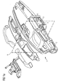
- Fig. 1a shows a first embodiment of an instrument panel according to the invention 1.
- This shows a frame structure 2, which is predominantly, especially in its upper area, provided with a decorative layer 8 on the visible side.
- visible is meant the side that will be associated with a later motor vehicle interior.
- Left side are in Fig. 1a still marked ventilation ducts or brackets for airbag modules shown and a steering column bracket (top left).
- the frame structure includes a holding member 4 for inserting electronic devices such as a car radio, a navigation device, etc.
- the holding member 4 has a central opening 3.
- the frame structure was produced in an injection molding process, wherein the frame-shaped holding element was produced here integrally. Subsequently, the frame structure 2 was inserted with a slush-skin in a tool and the space between the slush-skin and frame structure was foamed by isocyanate and polyol, so that in Fig. 1a to see, occupied with a decorative layer 8 frame structure 2 resulted.
- the decorative layer 8 does not go all the way to the edge of the opening 3.
- the decorative layer goes so far that a device to be inserted laterally at least partially overlaps the decorative layer in the edge region, so that no uncovered parts of the frame structure in this area are visible to the visible side of the vehicle interior to let.
- the frame structure 2 is constructed as a frame structure with line-shaped elements, wherein the line-shaped elements are partially closed with plastic plate elements 12.
- this is a framework structure, as in Fig. 3 is illustrated.
- the line-shaped elements and the plastic plate elements are made of the same plastic (polypropylene 30 with long glass fiber aggregate, this material has a flexural modulus in the range between 2500 and 3500 N / mm 2 ).
- the frame structure 2 has on its side facing away from the motor vehicle interior stiffening ribs (this in Fig. 3 indicated by an "X-ray view").
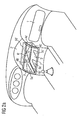
- Fig. 1b shows a section through the dashboard Fig. 1a according to section plane A (see Fig. 1a ). Shown here is the top view from the right, so on the driver side area.
- Fig. 1b shows in detail two substantially triangular elements, each serving as a slot for electronic devices.
- Electronic devices either in single-DIN or double-DIN format, can be inserted here, with no intermediate elements, such as intermediate frames necessary.
- the devices are inserted into the frame-shaped holding element 4, whereby a connecting edge 16 is provided, against which a section protruding laterally in the region of the panel of the device abuts (this is also particularly good in FIG Fig. 2b see, the local device is illustrated by the reference numeral 10).
- the holding element has detents in the present case, so that the device can be fixed in the triangular element 5a or the holding element 4 without additional fixing means.
- the triangular elements have towards the device in this case a peripheral edge, which protrudes from a substantially triangular base.
- This peripheral edge reinforcement results in a significant stiffening of the triangular elements 5a.
- these have a slight elasticity that it is possible, for example, to introduce on the triangular surface to a device 10 towards a locking lug which is pushed laterally outwardly by passing a corresponding locking tongue on the device 10 and then snaps to the device 10 accordingly fix.
- Rastungsde also can be additionally fixed by screws, if a particularly frequent removability of the devices is desired.
- Fig. 1b also shows that the decorative layer is angled in the area around the holding element 4. It can also be seen that the holding element with respect to the Vehicle interior assignable front of the instrument panel is set back.
- a rectangular opening 3" is provided, into which instruments and devices can be inserted, and behind the opening there is the center reinforcement 4a 'to 4f' and 5a 'to
- this support 4a 'to 4f' and 5a 'to 5c' has struts 4a 'to 4f' at the edges of a cuboid, these devices being used to hold devices in use In the case shown, they are substantially triangular and are fastened to one side of the triangle on the front side 7 'of the opening 3' in a material-locking manner.
- Fig. 2b shows a cross section through the opening 3 'of the holder according to the invention.
- the opening 3 ' here has steps 9a' and 9b ', over which the decor 8' extends to the holder 4a 'and 4b'.
- steps 9a' and 9b ' over which the decor 8' extends to the holder 4a 'and 4b'.
- a smooth appearance without significant steps is achieved.
- an electronic device 10 in the present case a car radio in a single DIN-slot format, the size dimensions of the essentially cuboid device, which shows a widening in the area of the control panel, is indicated by a dashed line.
- the device 10 is over Notches in the triangular element 5a 'engaged. Between device 10 and decorative layer 8 'is a joint of constant size to see, which is designated by the reference numeral 15'.
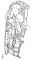
- Fig. 3 shows a frame structure in the "X-ray view".
- the line-shaped elements 11 actually have a ribbing or cross ribbing only on their side facing away from the vehicle interior 13. Between these line-shaped elements plastic plate elements 12 are arranged.
- frame structure on the one hand has an integrated center reinforcement or a holding element 4, also here a recording on a head-up display 15 is shown, this may have a corresponding receiving frame.
- FIG. 3 shown frame structure is so stable that can be dispensed with a continuous cross member between the A-pillars 14 of the motor vehicle.
Landscapes
- Engineering & Computer Science (AREA)
- Chemical & Material Sciences (AREA)
- Combustion & Propulsion (AREA)
- Transportation (AREA)
- Mechanical Engineering (AREA)
- Instrument Panels (AREA)
Claims (13)
- Procédé de fabrication d'un tableau de bord (1), dans lequel :a) une structure de cadre (2) est produite au cours d'un unique processus de moulage par injection et cette structure de cadre présente des éléments linéaires (11), qui sont obturés, par zones, par des éléments de plaque en matériau synthétique (12) et sont reliés par assemblage matériel, et
les éléments linéaires (11) présentent des nervures de renfort sur leur côté opposé à un futur habitacle (13) de véhicule automobile et la structure de cadre contient au moins un élément de retenue (4) en forme de cadre et cet élément de retenue en forme de cadre présente une ouverture (3) pour recevoir des appareils électroniques insérables (10), etb) l'appareil électronique (10) est inséré dans l'élément de retenue (4) en forme de cadre. - Procédé selon la revendication 1, caractérisé en ce que les éléments linéaires (11) présentent un noyau constitué de métal ou d'un matériau fibreux.
- Procédé selon la revendication 1 ou 2, caractérisé en ce que l'appareil (10) est un autoradio, un système de navigation GPS ou un affichage tête haute (Head-Up-Display).
- Procédé selon l'une quelconque des revendications précédentes, caractérisé en ce qu'avant l'insertion de l'appareil électronique (10), la structure de cadre (2) est revêtue d'une couche décorative.
- Procédé selon la revendication 4, caractérisé en ce que la couche décorative (8) est en cuir ou en matériau synthétique.
- Procédé selon la revendication 5, caractérisé en ce que les liaisons entre la couche décorative (8) et la structure de cadre (2) se font par application de colle ou de mousse.
- Procédé selon l'une quelconque des revendications 4 à 6, caractérisé en ce que l'appareil électronique (10) est inséré de sorte qu'il recouvre côté bord, par zones, la couche décorative (8).
- Procédé selon l'une quelconque des revendications précédentes, caractérisé en ce que, pour fabriquer la structure de cadre (2), on utilise un matériau synthétique dont le module d'élasticité à la flexion est compris entre 2000 et 3500 N/mm2.
- Tableau de bord (1) avec une structure de cadre (2) qui est produite selon un procédé de moulage par injection et qui contient au moins un élément de retenue en forme de cadre et cet élément de retenue (4) en forme de cadre présente une ouverture (3) pour recevoir des appareils électroniques insérables (10) et l'appareil électronique est inséré dans l'élément de retenue en forme de cadre,
caractérisé en ce que
la structure de cadre est produite au cours d'un unique processus de moulage par injection et cette structure de cadre présente des éléments linéaires (11), qui sont obturés, par zones, par des éléments de plaque en matériau synthétique (12) et sont reliés par assemblage matériel et en ce que les éléments linéaires présentent des nervures de renfort sur leur côté opposé à un futur habitacle de véhicule automobile. - Tableau de bord (1) selon la revendication 9, caractérisé en ce que la structure de cadre (2) du tableau de bord est reliée, d'une part, directement à une couche décorative (8) par application de colle ou de mousse et la structure de cadre peut être reliée, d'autre part, directement au véhicule automobile (14) et en ce que la stabilité de la structure de cadre (2) du tableau de bord (1) est conçue de manière à pouvoir renoncer à une traverse séparée s'étendant sur toute la largeur d'un véhicule automobile (14).
- Tableau de bord selon l'une quelconque des revendications 9 ou 10, caractérisé en ce que l'élément de retenue (4) est en retrait par rapport à l'avant du tableau de bord (1) qui peut être affecté à un habitacle de véhicule automobile (13).
- Tableau de bord selon la revendication 9, caractérisé en ce que la couche décorative (8) est rehaussée dans la zone environnante de l'appareil électronique.
- Tableau de bord selon l'une quelconque des revendications 9 ou 12, caractérisé en ce que l'on ne prévoit aucun cadre intermédiaire entre l'appareil électronique (10) et l'élément de retenue (4).
Applications Claiming Priority (3)
| Application Number | Priority Date | Filing Date | Title |
|---|---|---|---|
| DE102007035383 | 2007-07-26 | ||
| DE102007035382 | 2007-07-26 | ||
| DE102008006936A DE102008006936A1 (de) | 2007-07-26 | 2008-01-25 | Integrierte Center-Verstärkung |
Publications (2)
| Publication Number | Publication Date |
|---|---|
| EP2019026A1 EP2019026A1 (fr) | 2009-01-28 |
| EP2019026B1 true EP2019026B1 (fr) | 2010-11-17 |
Family
ID=39764956
Family Applications (1)
| Application Number | Title | Priority Date | Filing Date |
|---|---|---|---|
| EP20080075665 Not-in-force EP2019026B1 (fr) | 2007-07-26 | 2008-07-25 | Renforcement central intégré |
Country Status (1)
| Country | Link |
|---|---|
| EP (1) | EP2019026B1 (fr) |
Cited By (2)
| Publication number | Priority date | Publication date | Assignee | Title |
|---|---|---|---|---|
| EP3508399A1 (fr) | 2018-01-09 | 2019-07-10 | Motherson Innovations Company Limited | Structure de support autoportant pour un tableau de bord dans un véhicule, tableau de bord comprenant une telle structure de support et véhicule équipé d'un tel tableau de bord |
| EP4418033A1 (fr) * | 2023-02-20 | 2024-08-21 | Valeo Schalter und Sensoren GmbH | Unité de boîtier pour un affichage tête haute |
Families Citing this family (4)
| Publication number | Priority date | Publication date | Assignee | Title |
|---|---|---|---|---|
| DE102009047723A1 (de) | 2009-12-09 | 2011-06-16 | Robert Bosch Gmbh | Verfahren zur Montage von Anzeigemodulen in einer Instrumententafel |
| DE102011056699B4 (de) * | 2011-12-20 | 2018-11-08 | Benteler Automobiltechnik Gmbh | Verfahren zur Herstellung eines Instrumententafelträgers sowie Instrumententafelträger |
| EP3760466B1 (fr) | 2019-07-04 | 2023-06-07 | Motherson Innovations Company Limited | Structure de support autoportant pour un tableau de bord dans un véhicule, tableau de bord comprenant une telle structure de support, véhicule équipé d'un tel tableau de bord et procédé de fabrication d'un tel tableau de bord |
| DE102022120869A1 (de) | 2022-08-18 | 2024-02-29 | Kirchhoff Automotive Deutschland Gmbh | Instrumententafelträger |
Family Cites Families (4)
| Publication number | Priority date | Publication date | Assignee | Title |
|---|---|---|---|---|
| US5364159A (en) | 1993-06-15 | 1994-11-15 | Davidson Textron Inc. | Structural instrument panel carrier assembly |
| US7040686B2 (en) | 2002-06-28 | 2006-05-09 | Collins & Aikman Products Co. | Integrated center stack electronic module retention system |
| DE10317900B4 (de) | 2003-04-17 | 2007-10-31 | Siemens Ag | Instrumententafeleinheit |
| DE102006040032A1 (de) | 2006-08-23 | 2008-03-13 | Faurecia Innenraum Systeme Gmbh | Fahrzeug mit einer gegen einen Seitenaufprall ausgelegten Instrumententafel |
-
2008
- 2008-07-25 EP EP20080075665 patent/EP2019026B1/fr not_active Not-in-force
Cited By (2)
| Publication number | Priority date | Publication date | Assignee | Title |
|---|---|---|---|---|
| EP3508399A1 (fr) | 2018-01-09 | 2019-07-10 | Motherson Innovations Company Limited | Structure de support autoportant pour un tableau de bord dans un véhicule, tableau de bord comprenant une telle structure de support et véhicule équipé d'un tel tableau de bord |
| EP4418033A1 (fr) * | 2023-02-20 | 2024-08-21 | Valeo Schalter und Sensoren GmbH | Unité de boîtier pour un affichage tête haute |
Also Published As
| Publication number | Publication date |
|---|---|
| EP2019026A1 (fr) | 2009-01-28 |
Similar Documents
| Publication | Publication Date | Title |
|---|---|---|
| DE102008021103B4 (de) | Integriertes Verbundbauteil eines Kraftfahrzeugs und Verfahren zur Herstellung eines integrierten Verbundbauteils | |
| EP2019026B1 (fr) | Renforcement central intégré | |
| DE10158401B4 (de) | Moduldach für ein Kraftfahrzeug und Verfahren zu seiner Montage | |
| DE102011086701B4 (de) | Mittelkonsole für Fahrzeuge sowie Verfahren zu deren Herstellung | |
| DE10230410B4 (de) | Eigensteife Instrumentenaufnahmevorrichtung | |
| DE10296872B4 (de) | Armaturenbrett- und Teileanordnung | |
| DE102005004605A1 (de) | Querträgermodul für ein Kraftfahrzeug | |
| DE102011082651A1 (de) | Spiegelfuß für einen Außenspiegel eines Kraftfahrzeugs sowie Herstellungsverfahren für einen Spiegelfuß | |
| DE3806783A1 (de) | Instrumententafel | |
| DE102012104534A1 (de) | Innenverkleidung für ein Kraftfahrzeug, die einen Dachhimmel und einen Versteifungsrahmen aufweist, und Verfahren zu ihrer Herstellung | |
| EP3274215B1 (fr) | Procédé de fabrication d'un appui-tête pourvu d'un module fonctionnel intégré | |
| EP1925488B1 (fr) | Tableau de bord et son procédé de fabrication | |
| DE112006002513T5 (de) | Inneres Innenausstattungsteil eines Arbeitsfahrzeugs und Verfahren zur Herstellung desselben | |
| EP2525956A1 (fr) | Procédé de fabrication d'un élément de revêtement intérieur | |
| EP2178723A1 (fr) | Pièce moulée avec recouvrement intégré de coussin gonflable et tôle de recouvrement de coussin gonflable | |
| DE602005004699T2 (de) | Instrumententräger | |
| EP1791725B1 (fr) | Piece d'habillage comprenant une surface decorative | |
| EP1595747B1 (fr) | Console centrale constituée d'une partie de base et d'au moins un élément latéral | |
| DE102008006936A1 (de) | Integrierte Center-Verstärkung | |
| DE102007031585A1 (de) | Hutablage für ein Kraftfahrzeug und Kraftfahrzeug mit einer solchen Hutablage | |
| DE10249514B4 (de) | Armaturenbrettträger | |
| WO2022253975A1 (fr) | Composant pour un véhicule automobile, comprenant un support de tableau de bord et une unité, et procédé de fourniture dudit composant | |
| DE102017113355A1 (de) | Defrostkanal | |
| DE10241186B4 (de) | Dachmodul für ein Fahrzeug sowie Herstellungsverfahren dafür | |
| DE102024111221A1 (de) | Metallzierteil für ein Fahrzeug, Metallzierteil-System, Fahrzeug mit Metallzierteil-System und/oder Metallzierteil, Verfahren zum Herstellen des Metallzierteils und zur Ausbildung des Metallzierteil-Systems |
Legal Events
| Date | Code | Title | Description |
|---|---|---|---|
| PUAI | Public reference made under article 153(3) epc to a published international application that has entered the european phase |
Free format text: ORIGINAL CODE: 0009012 |
|
| AK | Designated contracting states |
Kind code of ref document: A1 Designated state(s): AT BE BG CH CY CZ DE DK EE ES FI FR GB GR HR HU IE IS IT LI LT LU LV MC MT NL NO PL PT RO SE SI SK TR |
|
| AX | Request for extension of the european patent |
Extension state: AL BA MK RS |
|
| 17P | Request for examination filed |
Effective date: 20090210 |
|
| 17Q | First examination report despatched |
Effective date: 20090408 |
|
| AKX | Designation fees paid |
Designated state(s): AT BE BG CH CY CZ DE DK EE ES FI FR GB GR HR HU IE IS IT LI LT LU LV MC MT NL NO PL PT RO SE SI SK TR |
|
| GRAC | Information related to communication of intention to grant a patent modified |
Free format text: ORIGINAL CODE: EPIDOSCIGR1 |
|
| GRAP | Despatch of communication of intention to grant a patent |
Free format text: ORIGINAL CODE: EPIDOSNIGR1 |
|
| GRAS | Grant fee paid |
Free format text: ORIGINAL CODE: EPIDOSNIGR3 |
|
| GRAA | (expected) grant |
Free format text: ORIGINAL CODE: 0009210 |
|
| AK | Designated contracting states |
Kind code of ref document: B1 Designated state(s): AT BE BG CH CY CZ DE DK EE ES FI FR GB GR HR HU IE IS IT LI LT LU LV MC MT NL NO PL PT RO SE SI SK TR |
|
| REG | Reference to a national code |
Ref country code: GB Ref legal event code: FG4D Free format text: NOT ENGLISH |
|
| REG | Reference to a national code |
Ref country code: CH Ref legal event code: EP |
|
| REG | Reference to a national code |
Ref country code: IE Ref legal event code: FG4D |
|
| REF | Corresponds to: |
Ref document number: 502008001805 Country of ref document: DE Date of ref document: 20101230 Kind code of ref document: P |
|
| REG | Reference to a national code |
Ref country code: NL Ref legal event code: VDEP Effective date: 20101117 |
|
| LTIE | Lt: invalidation of european patent or patent extension |
Effective date: 20101117 |
|
| PG25 | Lapsed in a contracting state [announced via postgrant information from national office to epo] |
Ref country code: NO Free format text: LAPSE BECAUSE OF FAILURE TO SUBMIT A TRANSLATION OF THE DESCRIPTION OR TO PAY THE FEE WITHIN THE PRESCRIBED TIME-LIMIT Effective date: 20110217 Ref country code: LT Free format text: LAPSE BECAUSE OF FAILURE TO SUBMIT A TRANSLATION OF THE DESCRIPTION OR TO PAY THE FEE WITHIN THE PRESCRIBED TIME-LIMIT Effective date: 20101117 |
|
| PG25 | Lapsed in a contracting state [announced via postgrant information from national office to epo] |
Ref country code: LV Free format text: LAPSE BECAUSE OF FAILURE TO SUBMIT A TRANSLATION OF THE DESCRIPTION OR TO PAY THE FEE WITHIN THE PRESCRIBED TIME-LIMIT Effective date: 20101117 Ref country code: SE Free format text: LAPSE BECAUSE OF FAILURE TO SUBMIT A TRANSLATION OF THE DESCRIPTION OR TO PAY THE FEE WITHIN THE PRESCRIBED TIME-LIMIT Effective date: 20101117 Ref country code: FI Free format text: LAPSE BECAUSE OF FAILURE TO SUBMIT A TRANSLATION OF THE DESCRIPTION OR TO PAY THE FEE WITHIN THE PRESCRIBED TIME-LIMIT Effective date: 20101117 Ref country code: PT Free format text: LAPSE BECAUSE OF FAILURE TO SUBMIT A TRANSLATION OF THE DESCRIPTION OR TO PAY THE FEE WITHIN THE PRESCRIBED TIME-LIMIT Effective date: 20110317 Ref country code: NL Free format text: LAPSE BECAUSE OF FAILURE TO SUBMIT A TRANSLATION OF THE DESCRIPTION OR TO PAY THE FEE WITHIN THE PRESCRIBED TIME-LIMIT Effective date: 20101117 Ref country code: IS Free format text: LAPSE BECAUSE OF FAILURE TO SUBMIT A TRANSLATION OF THE DESCRIPTION OR TO PAY THE FEE WITHIN THE PRESCRIBED TIME-LIMIT Effective date: 20110317 Ref country code: HR Free format text: LAPSE BECAUSE OF FAILURE TO SUBMIT A TRANSLATION OF THE DESCRIPTION OR TO PAY THE FEE WITHIN THE PRESCRIBED TIME-LIMIT Effective date: 20101117 Ref country code: SI Free format text: LAPSE BECAUSE OF FAILURE TO SUBMIT A TRANSLATION OF THE DESCRIPTION OR TO PAY THE FEE WITHIN THE PRESCRIBED TIME-LIMIT Effective date: 20101117 Ref country code: CY Free format text: LAPSE BECAUSE OF FAILURE TO SUBMIT A TRANSLATION OF THE DESCRIPTION OR TO PAY THE FEE WITHIN THE PRESCRIBED TIME-LIMIT Effective date: 20101117 Ref country code: BG Free format text: LAPSE BECAUSE OF FAILURE TO SUBMIT A TRANSLATION OF THE DESCRIPTION OR TO PAY THE FEE WITHIN THE PRESCRIBED TIME-LIMIT Effective date: 20110217 |
|
| REG | Reference to a national code |
Ref country code: IE Ref legal event code: FD4D |
|
| PG25 | Lapsed in a contracting state [announced via postgrant information from national office to epo] |
Ref country code: GR Free format text: LAPSE BECAUSE OF FAILURE TO SUBMIT A TRANSLATION OF THE DESCRIPTION OR TO PAY THE FEE WITHIN THE PRESCRIBED TIME-LIMIT Effective date: 20110218 |
|
| PG25 | Lapsed in a contracting state [announced via postgrant information from national office to epo] |
Ref country code: CZ Free format text: LAPSE BECAUSE OF FAILURE TO SUBMIT A TRANSLATION OF THE DESCRIPTION OR TO PAY THE FEE WITHIN THE PRESCRIBED TIME-LIMIT Effective date: 20101117 Ref country code: IE Free format text: LAPSE BECAUSE OF FAILURE TO SUBMIT A TRANSLATION OF THE DESCRIPTION OR TO PAY THE FEE WITHIN THE PRESCRIBED TIME-LIMIT Effective date: 20101117 Ref country code: ES Free format text: LAPSE BECAUSE OF FAILURE TO SUBMIT A TRANSLATION OF THE DESCRIPTION OR TO PAY THE FEE WITHIN THE PRESCRIBED TIME-LIMIT Effective date: 20110228 Ref country code: EE Free format text: LAPSE BECAUSE OF FAILURE TO SUBMIT A TRANSLATION OF THE DESCRIPTION OR TO PAY THE FEE WITHIN THE PRESCRIBED TIME-LIMIT Effective date: 20101117 |
|
| PG25 | Lapsed in a contracting state [announced via postgrant information from national office to epo] |
Ref country code: DK Free format text: LAPSE BECAUSE OF FAILURE TO SUBMIT A TRANSLATION OF THE DESCRIPTION OR TO PAY THE FEE WITHIN THE PRESCRIBED TIME-LIMIT Effective date: 20101117 Ref country code: PL Free format text: LAPSE BECAUSE OF FAILURE TO SUBMIT A TRANSLATION OF THE DESCRIPTION OR TO PAY THE FEE WITHIN THE PRESCRIBED TIME-LIMIT Effective date: 20101117 Ref country code: RO Free format text: LAPSE BECAUSE OF FAILURE TO SUBMIT A TRANSLATION OF THE DESCRIPTION OR TO PAY THE FEE WITHIN THE PRESCRIBED TIME-LIMIT Effective date: 20101117 Ref country code: SK Free format text: LAPSE BECAUSE OF FAILURE TO SUBMIT A TRANSLATION OF THE DESCRIPTION OR TO PAY THE FEE WITHIN THE PRESCRIBED TIME-LIMIT Effective date: 20101117 |
|
| PLBE | No opposition filed within time limit |
Free format text: ORIGINAL CODE: 0009261 |
|
| STAA | Information on the status of an ep patent application or granted ep patent |
Free format text: STATUS: NO OPPOSITION FILED WITHIN TIME LIMIT |
|
| 26N | No opposition filed |
Effective date: 20110818 |
|
| REG | Reference to a national code |
Ref country code: DE Ref legal event code: R097 Ref document number: 502008001805 Country of ref document: DE Effective date: 20110818 |
|
| PG25 | Lapsed in a contracting state [announced via postgrant information from national office to epo] |
Ref country code: IT Free format text: LAPSE BECAUSE OF FAILURE TO SUBMIT A TRANSLATION OF THE DESCRIPTION OR TO PAY THE FEE WITHIN THE PRESCRIBED TIME-LIMIT Effective date: 20101117 Ref country code: MT Free format text: LAPSE BECAUSE OF FAILURE TO SUBMIT A TRANSLATION OF THE DESCRIPTION OR TO PAY THE FEE WITHIN THE PRESCRIBED TIME-LIMIT Effective date: 20101117 |
|
| BERE | Be: lapsed |
Owner name: FAURECIA INNENRAUM SYSTEME G.M.B.H. Effective date: 20110731 |
|
| PG25 | Lapsed in a contracting state [announced via postgrant information from national office to epo] |
Ref country code: MC Free format text: LAPSE BECAUSE OF NON-PAYMENT OF DUE FEES Effective date: 20110731 |
|
| PG25 | Lapsed in a contracting state [announced via postgrant information from national office to epo] |
Ref country code: BE Free format text: LAPSE BECAUSE OF NON-PAYMENT OF DUE FEES Effective date: 20110731 |
|
| REG | Reference to a national code |
Ref country code: CH Ref legal event code: PL |
|
| GBPC | Gb: european patent ceased through non-payment of renewal fee |
Effective date: 20120725 |
|
| PG25 | Lapsed in a contracting state [announced via postgrant information from national office to epo] |
Ref country code: LI Free format text: LAPSE BECAUSE OF NON-PAYMENT OF DUE FEES Effective date: 20120731 Ref country code: GB Free format text: LAPSE BECAUSE OF NON-PAYMENT OF DUE FEES Effective date: 20120725 Ref country code: CH Free format text: LAPSE BECAUSE OF NON-PAYMENT OF DUE FEES Effective date: 20120731 |
|
| PG25 | Lapsed in a contracting state [announced via postgrant information from national office to epo] |
Ref country code: LU Free format text: LAPSE BECAUSE OF NON-PAYMENT OF DUE FEES Effective date: 20110725 |
|
| PG25 | Lapsed in a contracting state [announced via postgrant information from national office to epo] |
Ref country code: TR Free format text: LAPSE BECAUSE OF FAILURE TO SUBMIT A TRANSLATION OF THE DESCRIPTION OR TO PAY THE FEE WITHIN THE PRESCRIBED TIME-LIMIT Effective date: 20101117 |
|
| PG25 | Lapsed in a contracting state [announced via postgrant information from national office to epo] |
Ref country code: HU Free format text: LAPSE BECAUSE OF FAILURE TO SUBMIT A TRANSLATION OF THE DESCRIPTION OR TO PAY THE FEE WITHIN THE PRESCRIBED TIME-LIMIT Effective date: 20101117 |
|
| REG | Reference to a national code |
Ref country code: AT Ref legal event code: MM01 Ref document number: 488420 Country of ref document: AT Kind code of ref document: T Effective date: 20130725 |
|
| PG25 | Lapsed in a contracting state [announced via postgrant information from national office to epo] |
Ref country code: AT Free format text: LAPSE BECAUSE OF NON-PAYMENT OF DUE FEES Effective date: 20130725 |
|
| REG | Reference to a national code |
Ref country code: FR Ref legal event code: PLFP Year of fee payment: 9 |
|
| REG | Reference to a national code |
Ref country code: FR Ref legal event code: PLFP Year of fee payment: 10 |
|
| REG | Reference to a national code |
Ref country code: FR Ref legal event code: PLFP Year of fee payment: 11 |
|
| PGFP | Annual fee paid to national office [announced via postgrant information from national office to epo] |
Ref country code: FR Payment date: 20180621 Year of fee payment: 11 |
|
| PGFP | Annual fee paid to national office [announced via postgrant information from national office to epo] |
Ref country code: DE Payment date: 20180620 Year of fee payment: 11 |
|
| REG | Reference to a national code |
Ref country code: DE Ref legal event code: R119 Ref document number: 502008001805 Country of ref document: DE |
|
| PG25 | Lapsed in a contracting state [announced via postgrant information from national office to epo] |
Ref country code: DE Free format text: LAPSE BECAUSE OF NON-PAYMENT OF DUE FEES Effective date: 20200201 |
|
| PG25 | Lapsed in a contracting state [announced via postgrant information from national office to epo] |
Ref country code: FR Free format text: LAPSE BECAUSE OF NON-PAYMENT OF DUE FEES Effective date: 20190731 |