EP2019178A2 - Serrure à barres articulées - Google Patents
Serrure à barres articulées Download PDFInfo
- Publication number
- EP2019178A2 EP2019178A2 EP20080010992 EP08010992A EP2019178A2 EP 2019178 A2 EP2019178 A2 EP 2019178A2 EP 20080010992 EP20080010992 EP 20080010992 EP 08010992 A EP08010992 A EP 08010992A EP 2019178 A2 EP2019178 A2 EP 2019178A2
- Authority
- EP
- European Patent Office
- Prior art keywords
- lock
- bolt
- bar
- lock body
- locking
- Prior art date
- Legal status (The legal status is an assumption and is not a legal conclusion. Google has not performed a legal analysis and makes no representation as to the accuracy of the status listed.)
- Granted
Links
Images


Classifications
-
- E—FIXED CONSTRUCTIONS
- E05—LOCKS; KEYS; WINDOW OR DOOR FITTINGS; SAFES
- E05B—LOCKS; ACCESSORIES THEREFOR; HANDCUFFS
- E05B67/00—Padlocks; Details thereof
- E05B67/003—Chain, wire or cable locks
-
- E—FIXED CONSTRUCTIONS
- E05—LOCKS; KEYS; WINDOW OR DOOR FITTINGS; SAFES
- E05B—LOCKS; ACCESSORIES THEREFOR; HANDCUFFS
- E05B37/00—Permutation or combination locks; Puzzle locks
- E05B37/02—Permutation or combination locks; Puzzle locks with tumbler discs or rings arranged on a single axis, each disc being adjustable independently of the others
- E05B37/025—Permutation or combination locks; Puzzle locks with tumbler discs or rings arranged on a single axis, each disc being adjustable independently of the others in padlocks
-
- E—FIXED CONSTRUCTIONS
- E05—LOCKS; KEYS; WINDOW OR DOOR FITTINGS; SAFES
- E05B—LOCKS; ACCESSORIES THEREFOR; HANDCUFFS
- E05B17/00—Accessories in connection with locks
- E05B17/0054—Fraction or shear lines; Slip-clutches, resilient parts or the like for preventing damage when forced or slammed
- E05B17/0062—Fraction or shear lines; Slip-clutches, resilient parts or the like for preventing damage when forced or slammed with destructive disengagement
-
- E—FIXED CONSTRUCTIONS
- E05—LOCKS; KEYS; WINDOW OR DOOR FITTINGS; SAFES
- E05B—LOCKS; ACCESSORIES THEREFOR; HANDCUFFS
- E05B71/00—Locks specially adapted for bicycles, other than padlocks
-
- Y—GENERAL TAGGING OF NEW TECHNOLOGICAL DEVELOPMENTS; GENERAL TAGGING OF CROSS-SECTIONAL TECHNOLOGIES SPANNING OVER SEVERAL SECTIONS OF THE IPC; TECHNICAL SUBJECTS COVERED BY FORMER USPC CROSS-REFERENCE ART COLLECTIONS [XRACs] AND DIGESTS
- Y10—TECHNICAL SUBJECTS COVERED BY FORMER USPC
- Y10T—TECHNICAL SUBJECTS COVERED BY FORMER US CLASSIFICATION
- Y10T70/00—Locks
- Y10T70/40—Portable
- Y10T70/402—Fetters
- Y10T70/409—Shackles
-
- Y—GENERAL TAGGING OF NEW TECHNOLOGICAL DEVELOPMENTS; GENERAL TAGGING OF CROSS-SECTIONAL TECHNOLOGIES SPANNING OVER SEVERAL SECTIONS OF THE IPC; TECHNICAL SUBJECTS COVERED BY FORMER USPC CROSS-REFERENCE ART COLLECTIONS [XRACs] AND DIGESTS
- Y10—TECHNICAL SUBJECTS COVERED BY FORMER USPC
- Y10T—TECHNICAL SUBJECTS COVERED BY FORMER US CLASSIFICATION
- Y10T70/00—Locks
- Y10T70/40—Portable
- Y10T70/413—Padlocks
- Y10T70/417—Combination-controlled
- Y10T70/435—Flexible shackle
-
- Y—GENERAL TAGGING OF NEW TECHNOLOGICAL DEVELOPMENTS; GENERAL TAGGING OF CROSS-SECTIONAL TECHNOLOGIES SPANNING OVER SEVERAL SECTIONS OF THE IPC; TECHNICAL SUBJECTS COVERED BY FORMER USPC CROSS-REFERENCE ART COLLECTIONS [XRACs] AND DIGESTS
- Y10—TECHNICAL SUBJECTS COVERED BY FORMER USPC
- Y10T—TECHNICAL SUBJECTS COVERED BY FORMER US CLASSIFICATION
- Y10T70/00—Locks
- Y10T70/40—Portable
- Y10T70/413—Padlocks
- Y10T70/437—Key-controlled
- Y10T70/483—Flexible shackle
-
- Y—GENERAL TAGGING OF NEW TECHNOLOGICAL DEVELOPMENTS; GENERAL TAGGING OF CROSS-SECTIONAL TECHNOLOGIES SPANNING OVER SEVERAL SECTIONS OF THE IPC; TECHNICAL SUBJECTS COVERED BY FORMER USPC CROSS-REFERENCE ART COLLECTIONS [XRACs] AND DIGESTS
- Y10—TECHNICAL SUBJECTS COVERED BY FORMER USPC
- Y10T—TECHNICAL SUBJECTS COVERED BY FORMER US CLASSIFICATION
- Y10T70/00—Locks
- Y10T70/50—Special application
- Y10T70/5611—For control and machine elements
- Y10T70/5646—Rotary shaft
- Y10T70/565—Locked stationary
- Y10T70/5655—Housing-carried lock
- Y10T70/5664—Latching bolt
Definitions
- the present invention relates to a hinged bar lock comprising a lock body and a hinge bar having first and second ends, the first end permanently connected to the lock body, and the second end connectable to the lock body at a lock portion of the lock body.
- a bolt provided on the lock body can be selectively moved to a locking position in which the latch engages the second end of the hinge bar when it is connected to the lock body, or the latch can be moved to a release position in which the second end of the Articulated bar is released for removal from the lock body.
- Such a hinged bar lock is off DE 10 2005 040 066 A1 known and used, for example, to secure a bicycle to a bicycle stand, a lamp post or the like.
- hinge rods of the hinge bar bracket are unfolded, and a closing rod on which the second end of the hinge bar is formed is locked to the lock body, thereby forming a closed loop.
- This closed loop may, for example, engage around a frame portion of the bicycle and the bicycle stand, lamp post or the like, or the hinged bar handle encloses only a rim of the bicycle to prevent unauthorized persons from driving away.
- a lock cylinder is used, which is rotatably actuated by an associated key or other identification means to move the latch selectively in the locked position or in the release position.
- the invention has for its object to provide a hinged bar lock with a numerical locking mechanism that is easy to use and whose lock body has a small size.
- a hinged bar lock with the features of claim 1 and in particular by the fact that the lock has a coupled via a connecting portion with the latch actuator to move the latch from the locking position, in which the latch is biased in the release position and in that the lock body accommodates a number lock mechanism for selectively locking or releasing the lock, the operation means being disposed opposite to the lock area of the lock body opposite to the number lock mechanism.
- the number locking mechanism is intended to block the latch in said locking position or to release it for movement into said release position.
- the numerical locking mechanism may be a known number-locking mechanism having a plurality of juxtaposed, rotatable number rings that release the bolt of the toggle lock when setting a release number combination corresponding to a predetermined rotational position of the number rings to each other block the bar with other number combinations or rotary positions.
- the number-closing mechanism and the actuator are disposed on different sides with respect to the lock portion of the lock body.
- the bolt is biased in the locking position.
- the latch - if it is released by the number-locking mechanism - can be moved into the release position by simply pressing on the coupled via the connecting portion with the latch actuator.
- the actuating device is thus in particular a feeler device.
- the locking and unlocking of the second end of the hinge rod bracket on the lock body is particularly easy and comfortable possible when the number locking mechanism is in a position in which the latch is released.
- the actuator can be pressed to lock the actuator, then inserted the second end of the hinge rod bracket in the locking portion of the lock body and finally the actuator are released again.
- the actuating device can first be pressed, then the second end of the articulated rod bracket can be removed from the locking area of the lock body, and finally the actuating device can be released again.
- the lock body of the hinge pin lock can be made particularly compact due to the simple structure of the locking mechanism.
- said connecting portion which couples the actuator to the latch, is fixedly connected to the latch, in particular an integral part of the latch.
- the connecting portion with respect to the longitudinal axis of the bolt which corresponds to the axis of rotation of the numerical locking mechanism, laterally offset. Due to the eccentric arrangement of the connecting portion with respect to the longitudinal axis of the bolt, a breaking tool, such as a screwdriver, which is forcibly inserted into the housing channel for the connecting portion, not readily in the latch channel and thus in the Advancing area of the number lock mechanism. Thus, the security against breakage of the toggle bar lock can be increased.
- the connecting portion is formed weaker, in particular, the connecting portion has a smaller cross-sectional area than the part of the bolt, which is arranged in the locking position of the bolt in the locking region of the lock body.
- the connecting portion thus acts as a predetermined breaking point. If the connecting portion is broken, the bolt can not be moved and remains in the locking area of the lock housing, so that the second end of the hinged bar is blocked against removal from the lock body. It is sufficient if the connecting portion is formed weaker at least at one point, as the located in the locking position in the locking portion of the bolt.
- the second end of the Gelenkstabbügels on an outwardly open passage slot which in particular runs parallel to the removal direction of the Gelenkstabbügels.
- This passport passes inwardly into a latch receiving opening, which is widened with respect to the passage slot.
- the latch receiving aperture is adapted to permit engagement of the latch in the second end of the hinge bar strap to lock the second end of the hinge bar strap to the latch portion of the latch body.
- the width of the passage slot is smaller than the extension of the bolt receiving opening in the corresponding direction to prevent in the locking position of the bolt a threading of the bolt through the slot.
- the width of the passage slot corresponds to the width of the connecting portion or is greater than its width, so that the second end of the hinged bar handle despite the locking area penetrating connection portion can be inserted or removed from the lock body.
- the pass-through slot is preferably formed at the axial end of the closing rod of the articulated rod bracket in order to allow axial insertion of the locking rod into the locking region of the lock body with respect to the longitudinal axis of the locking rod.
- the pass-through slot can also be formed laterally of the axial end of the locking bar at the second end of the hinge rod bracket, in order to enable a lateral pivoting of the second end of the hinge rod bracket into the locking region of the lock body.
- the locking portion of the lock body comprises a support portion which engages in the bolt receiving opening of the second end of the hinge bar, wherein the width of the support portion corresponds at most to the width of the aforementioned pass slot.
- the latch is then stabilized with respect to a lateral application of force, for example when trying to forcibly pull the second end of the hinge bar out of the latch body, without the latch engaging a housing portion of the latch body beyond the latching area, that is, beyond the plane of movement of the latch bar got to.
- the stability of the articulated bar lock can be increased.
- the increased stability is achieved with a minimum axial stroke of the bolt, whereby an advantageous size of the lock body is made possible. Since the width of the support portion corresponds at most to the width of the passage slot, it can be ensured that the support section does not hinder the insertion of the second end of the hinge rod bracket into the locking region of the lock body.
- the support portion of the lock body engages in a formed on the connecting portion axially facing the end of the bolt support portion receiving, wherein the bolt adjacent to the support portion receiving a blocking region, which optionally abuts the support portion.
- the bolt on the connecting portion axially facing the end of a thickening, which is arranged in the locking position of the bolt in the locking region of the lock body.
- a thickening By thickening a laterally offset arrangement of the connecting portion relative to the longitudinal axis of the bolt can be facilitated.
- the contact area with which the latch cooperates lockingly with the second end of the hinged bar handle can be increased.
- the formation of a support section receptacle in the bolt can be facilitated.
- the thickening is preferably formed as a disc section. The thickening may be arranged eccentrically to the longitudinal axis of the bolt.
- the number-closing mechanism has a number-combination adjusting mechanism disposed at the axial end of the number-closing mechanism opposite to the locking portion. As a result, the adjustment is easily accessible when a new release number combination is to be set.
- the philosophicalkombinationsverstellmechanismus may be a per se known gestationverstellmechanismus.
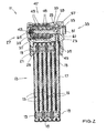
- the articulated bar lock shown has a lock body 11 and a hinged rod bracket 13 attached thereto.
- the articulated rod bracket 13 can, as in particular in FIGS Fig. 1 and 2 is shown folded into a compact unit and locked in this state also on the lock body 11.
- the Gelenkstabbügel 13 can also be unfolded (not shown) to a known per se To form a loop and thereby lock a bicycle or to another object, such as a bicycle stand to secure.
- the Gelenkstabbügel 13 has a plurality of hinge rods 15, one of which is designed as a closing rod 17.
- the joint rods 15, 17 are each formed flat and made of hardened steel.
- the articulated rods 15, 17 are hinged to one another in sequence in such a way by a respective rivet 19 that the articulation axes run parallel to one another and the articulated rod bracket 13 can be folded together in the manner of a folding rule.
- the longitudinal axes of the hinge rods 15, 17 extend in a plane parallel to each other.
- a first end 21 of the thus formed Gelenkstabbügels 13 is permanently articulated to the lock body 11.
- a second end 23 of the Gelenkstabbügels 13 is formed by the free end of the closing rod 17.
- the lock bar 17 has Fig. 3 an outwardly open passing slot 31 formed along the longitudinal axis of the lock bar 17.
- the passage slot 31 merges at its inner end into a circular latch receiving opening 41 whose diameter is greater than the width of the passage slot 31.
- the lock body 11 has an elongate housing 25, for example made of hardened steel, with a longitudinal axis which runs parallel to the joint axes of the joint rods 15, 17.
- a laterally projecting mounting portion 29 is integrally formed on the housing 25, to which the first end 21 of the Gelenkstabbügels 13 is articulated. Further, the housing 25 has at the first end 27 frontally a mounting opening 35, which opens into a cavity of the housing 25. Through the mounting hole 35, a lock mechanism is inserted into the housing 25, which includes an elongate latch 53 and a number-lock mechanism 47. The number-closing mechanism 47 has at its the mounting opening 35 end facing a philosophicalkombinationsverstellmechanismus. The mounting opening 35 is closed by a shutter disc 45 held by means of a securing ring 37.
- the housing 25 has a side receptacle 39.
- the side receptacle 39 is formed on a hinge bar 13 facing side surface of the housing 25 and serves to receive the second end 23 of the Gelenkstabbügels 13 and the free end of the Locking bar 17.
- the side receptacle 39 enters a locking area 59 (FIG. Fig. 2 ) of the lock body 11, in which the second end 23 of the Gelenkstabbügels 13 is when the locking bar 17 is completely inserted through the side receptacle 39 in the lock body 11.
- the extent of the locking portion 59 along said longitudinal axis of the housing 25 is determined by the clear height of the side receptacle 39, which in turn corresponds to the height of the free end 23 of the locking bar 17.
- a flat strap support 43 is integrally formed on the housing 25, which projects laterally from the housing 25 in alignment with the attachment section 29 at the first end 27 of the housing 25.
- the distance between the attachment portion 29 and the temple support 43 along the longitudinal axis of the housing 25 corresponds to the thickness or height of the folded hinge bar 13.
- the arranged in the cavity of the housing 25 numerical locking mechanism 47 comprises a plurality of juxtaposed, rotatable number rings 49 which form a latch channel, in which the latch 53 is inserted.
- the number rings 49 are adapted to allow each other at an adjustable predetermined rotational position an axial movement of the bolt 53 along its longitudinal axis, whereas in all other rotational positions of the number rings 49 to each other axial movement of the bolt 53 is blocked.
- the latch 53 has several along its longitudinal extent alternately arranged lateral elevations and depressions.
- the predetermined rotational position which may also be referred to as a latch release position, corresponds to a predetermined release-number combination which can be set in a known manner by the abovementioned number combination adjustment mechanism.
- the latch 53 protrudes from the latch channel formed by the number-closing mechanism 47 toward the second end 33 of the housing 25.
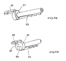
- a disc portion 57 At the second end 33 of the housing 25 facing the end of the bolt 53 is formed as a disc portion 57 ( Fig. 3 . 4 ), wherein the disc portion 57 is dimensioned larger in a direction radial to the longitudinal axis of the bolt 53, as the remaining portion of the bolt 53.
- the disc portion 57 is thereby arranged eccentrically to the longitudinal axis of the bolt 53.
- an elongated connecting portion 55 is integrally formed, on which a button 51 is attached.
- the connecting portion is laterally with respect to the longitudinal axis of the bolt 53 offset and arranged on an outer periphery of the disc portion 57.
- the key 51 is disposed opposite to the number-lock mechanism 47, that is, the key 51 is disposed on a different side of the lock portion 59 than the number-lock mechanism.
- a pushbutton section can be formed integrally in extension of the connecting section 55.
- Fig. 2 the bolt 53 is shown in the locking position, ie the bolt 53 engages in the second end 23 of the Gelenkstabbügels 13, wherein the latch 53 is biased by means of an inside of the shutter disc 45 supporting spring 65 in the direction of the locking position. More specifically, the disk portion 57 of the bolt 53 engages with the bolt receiving opening 41 of the lock bar 17, preventing retraction of the lock bar 17 from the lock body 11 due to the smaller width of the passport slot 31 with respect to the diameter of the disk portion 57.
- the connecting portion 55 extends in the locking position of the bolt 53 through the formed in the second end 23 of the Gelenkstabbügels 13 Passierschlitz 31 therethrough.
- the latch 53 has at its end facing the second end 33 of the housing 25, ie at the disc section 57, a support section receptacle 63 arranged adjacent to a blocking region 67 of the disc section 57 ( Fig. 4 ) into which a support section 61 (FIG. Fig. 2 ) of the lock body 11, wherein the support portion 61 is formed on an inner side of the second end 33 of the housing 25.
- the width of the support portion 61 corresponds in about the width of the passage slot 31 of the second end 23 of the hinge bar 13, so as not to hinder the insertion of the second end 23 of the hinge bar 13 in the lock body 11.
- the latch 53 In order to enable a release of the locking rod 17 of the lock body 11, the latch 53 by pressing the button 51, which is retractable in an outer recess of the housing 25, via the connecting portion 55 and against the bias of the spring 65 in a release position (not shown ) emotional. However, this presupposes that the number-closing mechanism 47 does not block the movement of the bolt 53.
- the disc portion 57 of the latch 53 By moving the latch 53 to the release position, the disc portion 57 of the latch 53 is temporarily disengaged from the latch receiving hole 41 of the lock rod 17, so that the lock rod 17 can be pulled out of the lock portion 59 and the side socket 39 of the lock body 11.
- the connecting portion 55 is located in the locking portion 59. However, the connecting portion 55, the removal of the locking rod 17 is not in the way, since the width of the connecting portion 55 corresponds approximately to the width of formed in the locking bar 17 Passierschlitzes 31st
Landscapes
- Lock And Its Accessories (AREA)
- Refuge Islands, Traffic Blockers, Or Guard Fence (AREA)
- Clamps And Clips (AREA)
Applications Claiming Priority (1)
| Application Number | Priority Date | Filing Date | Title |
|---|---|---|---|
| DE200710035116 DE102007035116A1 (de) | 2007-07-27 | 2007-07-27 | Gelenkstabschloss |
Publications (3)
| Publication Number | Publication Date |
|---|---|
| EP2019178A2 true EP2019178A2 (fr) | 2009-01-28 |
| EP2019178A3 EP2019178A3 (fr) | 2011-05-04 |
| EP2019178B1 EP2019178B1 (fr) | 2013-08-14 |
Family
ID=40043994
Family Applications (1)
| Application Number | Title | Priority Date | Filing Date |
|---|---|---|---|
| EP20080010992 Active EP2019178B1 (fr) | 2007-07-27 | 2008-06-17 | Serrure à barres articulées |
Country Status (4)
| Country | Link |
|---|---|
| US (1) | US7712339B2 (fr) |
| EP (1) | EP2019178B1 (fr) |
| CA (1) | CA2638047C (fr) |
| DE (1) | DE102007035116A1 (fr) |
Cited By (2)
| Publication number | Priority date | Publication date | Assignee | Title |
|---|---|---|---|---|
| US8621898B2 (en) | 2010-06-22 | 2014-01-07 | Sinoxlock (Kunshan) Co., Ltd. | Foldable lock |
| CN115898154A (zh) * | 2021-08-04 | 2023-04-04 | 金泰祥精密五金(昆山)有限公司 | 固定装置 |
Families Citing this family (34)
| Publication number | Priority date | Publication date | Assignee | Title |
|---|---|---|---|---|
| DE102009030036A1 (de) * | 2009-06-23 | 2010-12-30 | ABUS August Bremicker Söhne KG | Gelenkschloss |
| US8555682B2 (en) * | 2010-03-12 | 2013-10-15 | Christopher Trunek | Linkage lock |
| DE102010036636B4 (de) | 2010-07-27 | 2024-09-26 | Trelock Gmbh | Faltschloss |
| JP3171356U (ja) | 2010-12-20 | 2011-10-27 | 競泰股▲分▼有限公司 | ロック装置 |
| GB2495482B (en) * | 2011-10-05 | 2016-02-03 | Patrick Elson | Cycle accessory |
| US8904831B2 (en) | 2012-08-28 | 2014-12-09 | Master Lock Company Llc | Locking arrangements |
| DE202013102264U1 (de) | 2013-05-24 | 2013-07-09 | Sinox Co., Ltd. | Kettenschloß |
| DE102013210475A1 (de) | 2013-06-05 | 2014-12-11 | ABUS August Bremicker Söhne KG | Gelenkschloss |
| US8881559B1 (en) * | 2014-04-28 | 2014-11-11 | Vulcan Sports Co., Ltd. | Foldable lock |
| DE102015108072A1 (de) | 2015-05-21 | 2016-11-24 | ABUS August Bremicker Söhne KG | Zweirad-Schloss |
| TWM519165U (zh) * | 2015-08-18 | 2016-03-21 | 競泰股份有限公司 | 鍊條鎖 |
| TWM530338U (zh) | 2015-09-25 | 2016-10-11 | 競泰股份有限公司 | 鍊條鎖 |
| US9878752B2 (en) | 2015-10-30 | 2018-01-30 | Altor Locks, Llc | Folding anti-theft device |
| DE202016000005U1 (de) | 2016-01-05 | 2016-02-01 | Sinox Co., Ltd. | Kettenschloss |
| DE202016000006U1 (de) | 2016-01-05 | 2016-02-01 | Sinox Co., Ltd. | Kettenschloss |
| DE202017006952U1 (de) * | 2016-04-20 | 2019-01-17 | Ino Vision Ltd. | Fahrradfaltschloss mit Gelenkschutz |
| US10946914B2 (en) * | 2017-12-13 | 2021-03-16 | Adamant Conceptions Inc. | Chain assembly and a bicycle lock manufactured therefrom |
| US10801233B2 (en) | 2018-04-03 | 2020-10-13 | Knox Associates, Inc. | Fluid guard and absorber for locking devices |
| WO2020055891A1 (fr) * | 2018-09-11 | 2020-03-19 | Lobster Lock, Llc | Dispositif de verrouillage |
| TWM575470U (zh) | 2018-10-26 | 2019-03-11 | 競泰股份有限公司 | 鍊條鎖 |
| DE102019113377A1 (de) | 2019-05-20 | 2020-11-26 | ABUS August Bremicker Söhne Kommanditgesellschaft | Gelenkschloss |
| DE102019113387A1 (de) | 2019-05-20 | 2020-11-26 | ABUS August Bremicker Söhne Kommanditgesellschaft | Gelenkschloss |
| DE102019113388A1 (de) | 2019-05-20 | 2020-11-26 | ABUS August Bremicker Söhne Kommanditgesellschaft | Gelenkschloss |
| DE102019113378A1 (de) | 2019-05-20 | 2020-11-26 | ABUS August Bremicker Söhne Kommanditgesellschaft | Gelenkschloss |
| USD974872S1 (en) * | 2020-06-09 | 2023-01-10 | ABUS August Bremicker Söhne KG | Lock |
| DE102020116154B3 (de) | 2020-06-18 | 2021-05-27 | ABUS August Bremicker Söhne Kommanditgesellschaft | Halterung für ein tragbares Schloss |
| TWD215869S (zh) * | 2020-09-23 | 2021-12-11 | 競泰股份有限公司 | 折疊鎖 |
| TWM618643U (zh) | 2021-06-25 | 2021-10-21 | 林澤浩 | 固定裝置 |
| US12077988B2 (en) | 2021-12-08 | 2024-09-03 | Schlage Lock Company Llc | Portable lock apparatus |
| TWM627717U (zh) | 2021-12-28 | 2022-06-01 | 競泰股份有限公司 | 盤形鎖 |
| USD1026616S1 (en) * | 2022-01-29 | 2024-05-14 | Shenzhen Jinma Lock Industry Co., Ltd. | Bicycle lock |
| DE102023108955A1 (de) * | 2023-04-06 | 2024-10-10 | ABUS August Bremicker Söhne Kommanditgesellschaft | Schloss |
| DE102023108957A1 (de) * | 2023-04-06 | 2024-10-10 | ABUS August Bremicker Söhne Kommanditgesellschaft | Gelenkstabanordnung für ein Gelenkstabschloss sowie Gelenkstabschloss |
| TWM662547U (zh) | 2024-08-30 | 2024-11-01 | 競泰股份有限公司 | 固定裝置 |
Citations (1)
| Publication number | Priority date | Publication date | Assignee | Title |
|---|---|---|---|---|
| DE102005040066A1 (de) | 2005-08-24 | 2007-03-01 | ABUS August Bremicker Söhne KG | Gelenkschloss |
Family Cites Families (20)
| Publication number | Priority date | Publication date | Assignee | Title |
|---|---|---|---|---|
| US1718723A (en) * | 1928-03-26 | 1929-06-25 | Williams Harry | Padlock |
| DE3410047C2 (de) * | 1983-03-23 | 1986-09-25 | S. Franzen Söhne (GmbH & Co), 5650 Solingen | Permutationsschloß mit Schlüsselgeheimnis-Neueinstellvorrichtung |
| JPH0742821B2 (ja) * | 1993-03-24 | 1995-05-10 | 株式会社クローバー | 車両用錠装置 |
| TW260732B (fr) * | 1993-09-08 | 1995-10-21 | Winkhaus Fa August | |
| IT1285598B1 (it) * | 1996-03-07 | 1998-06-18 | I P Innovative Products Srl | Dispositivo antifurto pieghevole |
| US5791169A (en) * | 1997-08-27 | 1998-08-11 | Kuo; Lambert | U-shape lock |
| US5924313A (en) * | 1998-09-09 | 1999-07-20 | Kuo; Lambert | Combination lock with a device for changing the combination |
| US6101852A (en) * | 1999-03-05 | 2000-08-15 | Compx International Inc. | Padlock with removable shackle |
| US6386005B1 (en) * | 2001-04-24 | 2002-05-14 | Lambert Kuo | Combination lock |
| TW534155U (en) * | 2001-12-31 | 2003-05-21 | Jiun-De You | Improved structure of cable locks |
| TW543692U (en) * | 2002-09-30 | 2003-07-21 | Jin Tay Ind Co Ltd | Anti-thieving device of PDA and charger |
| TWM247656U (en) * | 2003-08-26 | 2004-10-21 | Sinox Co Ltd | Lock device |
| US6799446B1 (en) * | 2003-11-25 | 2004-10-05 | Jaeyou Co., Ltd. | Combination lock changeable in combination |
| EP1536091A1 (fr) * | 2003-11-27 | 2005-06-01 | Chen, Meng-Fu | Serrure pour motocyclettes à verrouillage/déverrouillage à plusieurs étapes |
| US6820448B1 (en) * | 2004-03-30 | 2004-11-23 | Hui-Hua Hsieh | Bike and motorcycle padlock |
| WO2006016280A2 (fr) * | 2004-08-03 | 2006-02-16 | The Sun Lock Company Ltd. | Construction de cadenas de haute securite |
| TWM271062U (en) * | 2004-12-21 | 2005-07-21 | Sinox Co Ltd | Padlock |
| US7185518B1 (en) * | 2005-10-07 | 2007-03-06 | Ho E Screw & Hardware Co., Ltd. | Safety lock for computer |
| TWM315251U (en) * | 2006-11-17 | 2007-07-11 | Wen-Chyun Su | Lock structure |
| US7481084B1 (en) * | 2008-04-08 | 2009-01-27 | Chun-Hsien Wu | Foldable lock structure |
-
2007
- 2007-07-27 DE DE200710035116 patent/DE102007035116A1/de not_active Withdrawn
-
2008
- 2008-06-17 EP EP20080010992 patent/EP2019178B1/fr active Active
- 2008-07-17 CA CA 2638047 patent/CA2638047C/fr not_active Expired - Fee Related
- 2008-07-21 US US12/176,723 patent/US7712339B2/en active Active
Patent Citations (1)
| Publication number | Priority date | Publication date | Assignee | Title |
|---|---|---|---|---|
| DE102005040066A1 (de) | 2005-08-24 | 2007-03-01 | ABUS August Bremicker Söhne KG | Gelenkschloss |
Cited By (2)
| Publication number | Priority date | Publication date | Assignee | Title |
|---|---|---|---|---|
| US8621898B2 (en) | 2010-06-22 | 2014-01-07 | Sinoxlock (Kunshan) Co., Ltd. | Foldable lock |
| CN115898154A (zh) * | 2021-08-04 | 2023-04-04 | 金泰祥精密五金(昆山)有限公司 | 固定装置 |
Also Published As
| Publication number | Publication date |
|---|---|
| EP2019178B1 (fr) | 2013-08-14 |
| EP2019178A3 (fr) | 2011-05-04 |
| CA2638047A1 (fr) | 2009-01-27 |
| DE102007035116A1 (de) | 2009-01-29 |
| CA2638047C (fr) | 2014-09-30 |
| US20090025437A1 (en) | 2009-01-29 |
| US7712339B2 (en) | 2010-05-11 |
Similar Documents
| Publication | Publication Date | Title |
|---|---|---|
| EP2019178B1 (fr) | Serrure à barres articulées | |
| DE102005040066B4 (de) | Gelenkschloss | |
| DE69806907T2 (de) | Verschlussvorrichtung für eine tür | |
| DE69819234T2 (de) | Vorhängeschloss | |
| EP2267256B1 (fr) | Cadenas | |
| EP0476229B1 (fr) | Etuer de serrure avec verrouillage basculant | |
| EP3741932B1 (fr) | Verrou d'aiguille à articulation | |
| EP2868850B1 (fr) | Cadenas | |
| EP0369107A2 (fr) | Serrure cylindrique | |
| DE102013210475A1 (de) | Gelenkschloss | |
| WO2012100950A1 (fr) | Cadenas | |
| EP3517713B1 (fr) | Dispositif de fermeture | |
| WO2023217448A1 (fr) | Verrou à manille avec blindage soudé | |
| DE102005063514B4 (de) | Gelenkschloss | |
| DE10215535A1 (de) | Schloss | |
| DE202007016091U1 (de) | Treibstangenschloss | |
| DE102014109833A1 (de) | Gerüstschloss | |
| DE2927008A1 (de) | Tuerschloss, insbesondere fuer haus- und wohnungsabschlusstueren | |
| DE10318707B4 (de) | Sicherheitseinrichtung | |
| EP3095932B1 (fr) | Serrure a deux roues | |
| DE102005026930B4 (de) | Vorhangschloss | |
| EP3741935B1 (fr) | Verrou d'aiguille à articulation | |
| DE202005021411U1 (de) | Gelenkschloss | |
| DE10156632C1 (de) | Türschloss, insbesondere Einsteckschloss | |
| DE202005021748U1 (de) | Gelenkschloss |
Legal Events
| Date | Code | Title | Description |
|---|---|---|---|
| PUAI | Public reference made under article 153(3) epc to a published international application that has entered the european phase |
Free format text: ORIGINAL CODE: 0009012 |
|
| AK | Designated contracting states |
Kind code of ref document: A2 Designated state(s): AT BE BG CH CY CZ DE DK EE ES FI FR GB GR HR HU IE IS IT LI LT LU LV MC MT NL NO PL PT RO SE SI SK TR |
|
| AX | Request for extension of the european patent |
Extension state: AL BA MK RS |
|
| PUAL | Search report despatched |
Free format text: ORIGINAL CODE: 0009013 |
|
| AK | Designated contracting states |
Kind code of ref document: A3 Designated state(s): AT BE BG CH CY CZ DE DK EE ES FI FR GB GR HR HU IE IS IT LI LT LU LV MC MT NL NO PL PT RO SE SI SK TR |
|
| AX | Request for extension of the european patent |
Extension state: AL BA MK RS |
|
| RIC1 | Information provided on ipc code assigned before grant |
Ipc: E05B 71/00 20060101ALN20081204BHEP Ipc: E05B 37/02 20060101ALI20110328BHEP Ipc: E05B 17/00 20060101ALI20110328BHEP Ipc: E05B 67/06 20060101AFI20081204BHEP |
|
| 17P | Request for examination filed |
Effective date: 20111031 |
|
| AKX | Designation fees paid |
Designated state(s): AT BE BG CH CY CZ DE DK EE ES FI FR GB GR HR HU IE IS IT LI LT LU LV MC MT NL NO PL PT RO SE SI SK TR |
|
| RIC1 | Information provided on ipc code assigned before grant |
Ipc: E05B 17/00 20060101ALI20121112BHEP Ipc: E05B 71/00 20060101ALN20121112BHEP Ipc: E05B 67/06 20060101AFI20121112BHEP Ipc: E05B 37/02 20060101ALI20121112BHEP |
|
| RIC1 | Information provided on ipc code assigned before grant |
Ipc: E05B 71/00 20060101ALN20121220BHEP Ipc: E05B 37/02 20060101ALI20121220BHEP Ipc: E05B 67/06 20060101AFI20121220BHEP Ipc: E05B 17/00 20060101ALI20121220BHEP |
|
| GRAP | Despatch of communication of intention to grant a patent |
Free format text: ORIGINAL CODE: EPIDOSNIGR1 |
|
| GRAS | Grant fee paid |
Free format text: ORIGINAL CODE: EPIDOSNIGR3 |
|
| GRAA | (expected) grant |
Free format text: ORIGINAL CODE: 0009210 |
|
| AK | Designated contracting states |
Kind code of ref document: B1 Designated state(s): AT BE BG CH CY CZ DE DK EE ES FI FR GB GR HR HU IE IS IT LI LT LU LV MC MT NL NO PL PT RO SE SI SK TR |
|
| REG | Reference to a national code |
Ref country code: GB Ref legal event code: FG4D Free format text: NOT ENGLISH |
|
| REG | Reference to a national code |
Ref country code: CH Ref legal event code: NV Representative=s name: DR. GRAF AND PARTNER AG INTELLECTUAL PROPERTY, CH Ref country code: CH Ref legal event code: EP Ref country code: AT Ref legal event code: REF Ref document number: 626989 Country of ref document: AT Kind code of ref document: T Effective date: 20130815 |
|
| REG | Reference to a national code |
Ref country code: IE Ref legal event code: FG4D Free format text: LANGUAGE OF EP DOCUMENT: GERMAN |
|
| REG | Reference to a national code |
Ref country code: DE Ref legal event code: R096 Ref document number: 502008010461 Country of ref document: DE Effective date: 20131010 |
|
| REG | Reference to a national code |
Ref country code: NL Ref legal event code: VDEP Effective date: 20130814 |
|
| REG | Reference to a national code |
Ref country code: LT Ref legal event code: MG4D |
|
| PG25 | Lapsed in a contracting state [announced via postgrant information from national office to epo] |
Ref country code: SE Free format text: LAPSE BECAUSE OF FAILURE TO SUBMIT A TRANSLATION OF THE DESCRIPTION OR TO PAY THE FEE WITHIN THE PRESCRIBED TIME-LIMIT Effective date: 20130814 Ref country code: IS Free format text: LAPSE BECAUSE OF FAILURE TO SUBMIT A TRANSLATION OF THE DESCRIPTION OR TO PAY THE FEE WITHIN THE PRESCRIBED TIME-LIMIT Effective date: 20131214 Ref country code: PT Free format text: LAPSE BECAUSE OF FAILURE TO SUBMIT A TRANSLATION OF THE DESCRIPTION OR TO PAY THE FEE WITHIN THE PRESCRIBED TIME-LIMIT Effective date: 20131216 Ref country code: HR Free format text: LAPSE BECAUSE OF FAILURE TO SUBMIT A TRANSLATION OF THE DESCRIPTION OR TO PAY THE FEE WITHIN THE PRESCRIBED TIME-LIMIT Effective date: 20130814 Ref country code: NO Free format text: LAPSE BECAUSE OF FAILURE TO SUBMIT A TRANSLATION OF THE DESCRIPTION OR TO PAY THE FEE WITHIN THE PRESCRIBED TIME-LIMIT Effective date: 20131114 Ref country code: LT Free format text: LAPSE BECAUSE OF FAILURE TO SUBMIT A TRANSLATION OF THE DESCRIPTION OR TO PAY THE FEE WITHIN THE PRESCRIBED TIME-LIMIT Effective date: 20130814 Ref country code: CY Free format text: LAPSE BECAUSE OF FAILURE TO SUBMIT A TRANSLATION OF THE DESCRIPTION OR TO PAY THE FEE WITHIN THE PRESCRIBED TIME-LIMIT Effective date: 20130724 |
|
| PG25 | Lapsed in a contracting state [announced via postgrant information from national office to epo] |
Ref country code: FI Free format text: LAPSE BECAUSE OF FAILURE TO SUBMIT A TRANSLATION OF THE DESCRIPTION OR TO PAY THE FEE WITHIN THE PRESCRIBED TIME-LIMIT Effective date: 20130814 Ref country code: PL Free format text: LAPSE BECAUSE OF FAILURE TO SUBMIT A TRANSLATION OF THE DESCRIPTION OR TO PAY THE FEE WITHIN THE PRESCRIBED TIME-LIMIT Effective date: 20130814 Ref country code: LV Free format text: LAPSE BECAUSE OF FAILURE TO SUBMIT A TRANSLATION OF THE DESCRIPTION OR TO PAY THE FEE WITHIN THE PRESCRIBED TIME-LIMIT Effective date: 20130814 Ref country code: SI Free format text: LAPSE BECAUSE OF FAILURE TO SUBMIT A TRANSLATION OF THE DESCRIPTION OR TO PAY THE FEE WITHIN THE PRESCRIBED TIME-LIMIT Effective date: 20130814 |
|
| PG25 | Lapsed in a contracting state [announced via postgrant information from national office to epo] |
Ref country code: CY Free format text: LAPSE BECAUSE OF FAILURE TO SUBMIT A TRANSLATION OF THE DESCRIPTION OR TO PAY THE FEE WITHIN THE PRESCRIBED TIME-LIMIT Effective date: 20130814 |
|
| PG25 | Lapsed in a contracting state [announced via postgrant information from national office to epo] |
Ref country code: EE Free format text: LAPSE BECAUSE OF FAILURE TO SUBMIT A TRANSLATION OF THE DESCRIPTION OR TO PAY THE FEE WITHIN THE PRESCRIBED TIME-LIMIT Effective date: 20130814 Ref country code: DK Free format text: LAPSE BECAUSE OF FAILURE TO SUBMIT A TRANSLATION OF THE DESCRIPTION OR TO PAY THE FEE WITHIN THE PRESCRIBED TIME-LIMIT Effective date: 20130814 Ref country code: CZ Free format text: LAPSE BECAUSE OF FAILURE TO SUBMIT A TRANSLATION OF THE DESCRIPTION OR TO PAY THE FEE WITHIN THE PRESCRIBED TIME-LIMIT Effective date: 20130814 Ref country code: RO Free format text: LAPSE BECAUSE OF FAILURE TO SUBMIT A TRANSLATION OF THE DESCRIPTION OR TO PAY THE FEE WITHIN THE PRESCRIBED TIME-LIMIT Effective date: 20130814 Ref country code: SK Free format text: LAPSE BECAUSE OF FAILURE TO SUBMIT A TRANSLATION OF THE DESCRIPTION OR TO PAY THE FEE WITHIN THE PRESCRIBED TIME-LIMIT Effective date: 20130814 Ref country code: NL Free format text: LAPSE BECAUSE OF FAILURE TO SUBMIT A TRANSLATION OF THE DESCRIPTION OR TO PAY THE FEE WITHIN THE PRESCRIBED TIME-LIMIT Effective date: 20130814 |
|
| PG25 | Lapsed in a contracting state [announced via postgrant information from national office to epo] |
Ref country code: ES Free format text: LAPSE BECAUSE OF FAILURE TO SUBMIT A TRANSLATION OF THE DESCRIPTION OR TO PAY THE FEE WITHIN THE PRESCRIBED TIME-LIMIT Effective date: 20130814 Ref country code: IT Free format text: LAPSE BECAUSE OF FAILURE TO SUBMIT A TRANSLATION OF THE DESCRIPTION OR TO PAY THE FEE WITHIN THE PRESCRIBED TIME-LIMIT Effective date: 20130814 |
|
| PLBE | No opposition filed within time limit |
Free format text: ORIGINAL CODE: 0009261 |
|
| STAA | Information on the status of an ep patent application or granted ep patent |
Free format text: STATUS: NO OPPOSITION FILED WITHIN TIME LIMIT |
|
| 26N | No opposition filed |
Effective date: 20140515 |
|
| REG | Reference to a national code |
Ref country code: DE Ref legal event code: R097 Ref document number: 502008010461 Country of ref document: DE Effective date: 20140515 |
|
| PG25 | Lapsed in a contracting state [announced via postgrant information from national office to epo] |
Ref country code: LU Free format text: LAPSE BECAUSE OF FAILURE TO SUBMIT A TRANSLATION OF THE DESCRIPTION OR TO PAY THE FEE WITHIN THE PRESCRIBED TIME-LIMIT Effective date: 20140617 Ref country code: MC Free format text: LAPSE BECAUSE OF FAILURE TO SUBMIT A TRANSLATION OF THE DESCRIPTION OR TO PAY THE FEE WITHIN THE PRESCRIBED TIME-LIMIT Effective date: 20130814 |
|
| GBPC | Gb: european patent ceased through non-payment of renewal fee |
Effective date: 20140617 |
|
| REG | Reference to a national code |
Ref country code: IE Ref legal event code: MM4A |
|
| PG25 | Lapsed in a contracting state [announced via postgrant information from national office to epo] |
Ref country code: IE Free format text: LAPSE BECAUSE OF NON-PAYMENT OF DUE FEES Effective date: 20140617 |
|
| PG25 | Lapsed in a contracting state [announced via postgrant information from national office to epo] |
Ref country code: GB Free format text: LAPSE BECAUSE OF NON-PAYMENT OF DUE FEES Effective date: 20140617 |
|
| PG25 | Lapsed in a contracting state [announced via postgrant information from national office to epo] |
Ref country code: MT Free format text: LAPSE BECAUSE OF FAILURE TO SUBMIT A TRANSLATION OF THE DESCRIPTION OR TO PAY THE FEE WITHIN THE PRESCRIBED TIME-LIMIT Effective date: 20130814 |
|
| PG25 | Lapsed in a contracting state [announced via postgrant information from national office to epo] |
Ref country code: BG Free format text: LAPSE BECAUSE OF FAILURE TO SUBMIT A TRANSLATION OF THE DESCRIPTION OR TO PAY THE FEE WITHIN THE PRESCRIBED TIME-LIMIT Effective date: 20130814 |
|
| REG | Reference to a national code |
Ref country code: FR Ref legal event code: PLFP Year of fee payment: 9 |
|
| PG25 | Lapsed in a contracting state [announced via postgrant information from national office to epo] |
Ref country code: GR Free format text: LAPSE BECAUSE OF FAILURE TO SUBMIT A TRANSLATION OF THE DESCRIPTION OR TO PAY THE FEE WITHIN THE PRESCRIBED TIME-LIMIT Effective date: 20130814 |
|
| PG25 | Lapsed in a contracting state [announced via postgrant information from national office to epo] |
Ref country code: HU Free format text: LAPSE BECAUSE OF FAILURE TO SUBMIT A TRANSLATION OF THE DESCRIPTION OR TO PAY THE FEE WITHIN THE PRESCRIBED TIME-LIMIT; INVALID AB INITIO Effective date: 20080617 Ref country code: TR Free format text: LAPSE BECAUSE OF FAILURE TO SUBMIT A TRANSLATION OF THE DESCRIPTION OR TO PAY THE FEE WITHIN THE PRESCRIBED TIME-LIMIT Effective date: 20130814 Ref country code: BE Free format text: LAPSE BECAUSE OF FAILURE TO SUBMIT A TRANSLATION OF THE DESCRIPTION OR TO PAY THE FEE WITHIN THE PRESCRIBED TIME-LIMIT Effective date: 20140630 |
|
| REG | Reference to a national code |
Ref country code: FR Ref legal event code: PLFP Year of fee payment: 10 |
|
| REG | Reference to a national code |
Ref country code: FR Ref legal event code: PLFP Year of fee payment: 11 |
|
| PGFP | Annual fee paid to national office [announced via postgrant information from national office to epo] |
Ref country code: CH Payment date: 20200618 Year of fee payment: 13 |
|
| PGFP | Annual fee paid to national office [announced via postgrant information from national office to epo] |
Ref country code: FR Payment date: 20210622 Year of fee payment: 14 |
|
| PGFP | Annual fee paid to national office [announced via postgrant information from national office to epo] |
Ref country code: AT Payment date: 20210621 Year of fee payment: 14 |
|
| REG | Reference to a national code |
Ref country code: CH Ref legal event code: PL |
|
| PG25 | Lapsed in a contracting state [announced via postgrant information from national office to epo] |
Ref country code: LI Free format text: LAPSE BECAUSE OF NON-PAYMENT OF DUE FEES Effective date: 20210630 Ref country code: CH Free format text: LAPSE BECAUSE OF NON-PAYMENT OF DUE FEES Effective date: 20210630 |
|
| REG | Reference to a national code |
Ref country code: AT Ref legal event code: MM01 Ref document number: 626989 Country of ref document: AT Kind code of ref document: T Effective date: 20220617 |
|
| PG25 | Lapsed in a contracting state [announced via postgrant information from national office to epo] |
Ref country code: FR Free format text: LAPSE BECAUSE OF NON-PAYMENT OF DUE FEES Effective date: 20220630 Ref country code: AT Free format text: LAPSE BECAUSE OF NON-PAYMENT OF DUE FEES Effective date: 20220617 |
|
| PGFP | Annual fee paid to national office [announced via postgrant information from national office to epo] |
Ref country code: DE Payment date: 20250827 Year of fee payment: 18 |