EP2019186B1 - Pale - Google Patents
Pale Download PDFInfo
- Publication number
- EP2019186B1 EP2019186B1 EP07741192.4A EP07741192A EP2019186B1 EP 2019186 B1 EP2019186 B1 EP 2019186B1 EP 07741192 A EP07741192 A EP 07741192A EP 2019186 B1 EP2019186 B1 EP 2019186B1
- Authority
- EP
- European Patent Office
- Prior art keywords
- suction surface
- blade
- fluid
- edge portion
- accordance
- Prior art date
- Legal status (The legal status is an assumption and is not a legal conclusion. Google has not performed a legal analysis and makes no representation as to the accuracy of the status listed.)
- Active
Links
Images






Classifications
-
- F—MECHANICAL ENGINEERING; LIGHTING; HEATING; WEAPONS; BLASTING
- F04—POSITIVE - DISPLACEMENT MACHINES FOR LIQUIDS; PUMPS FOR LIQUIDS OR ELASTIC FLUIDS
- F04D—NON-POSITIVE-DISPLACEMENT PUMPS
- F04D29/00—Details, component parts, or accessories
- F04D29/26—Rotors specially for elastic fluids
- F04D29/32—Rotors specially for elastic fluids for axial flow pumps
- F04D29/321—Rotors specially for elastic fluids for axial flow pumps for axial flow compressors
- F04D29/324—Blades
-
- F—MECHANICAL ENGINEERING; LIGHTING; HEATING; WEAPONS; BLASTING
- F01—MACHINES OR ENGINES IN GENERAL; ENGINE PLANTS IN GENERAL; STEAM ENGINES
- F01D—NON-POSITIVE DISPLACEMENT MACHINES OR ENGINES, e.g. STEAM TURBINES
- F01D5/00—Blades; Blade-carrying members; Heating, heat-insulating, cooling or antivibration means on the blades or the members
- F01D5/12—Blades
- F01D5/14—Form or construction
- F01D5/141—Shape, i.e. outer, aerodynamic form
- F01D5/145—Means for influencing boundary layers or secondary circulations
-
- F—MECHANICAL ENGINEERING; LIGHTING; HEATING; WEAPONS; BLASTING
- F04—POSITIVE - DISPLACEMENT MACHINES FOR LIQUIDS; PUMPS FOR LIQUIDS OR ELASTIC FLUIDS
- F04D—NON-POSITIVE-DISPLACEMENT PUMPS
- F04D29/00—Details, component parts, or accessories
- F04D29/66—Combating cavitation, whirls, noise, vibration or the like; Balancing
- F04D29/68—Combating cavitation, whirls, noise, vibration or the like; Balancing by influencing boundary layers
- F04D29/681—Combating cavitation, whirls, noise, vibration or the like; Balancing by influencing boundary layers especially adapted for elastic fluid pumps
-
- F—MECHANICAL ENGINEERING; LIGHTING; HEATING; WEAPONS; BLASTING
- F05—INDEXING SCHEMES RELATING TO ENGINES OR PUMPS IN VARIOUS SUBCLASSES OF CLASSES F01-F04
- F05D—INDEXING SCHEME FOR ASPECTS RELATING TO NON-POSITIVE-DISPLACEMENT MACHINES OR ENGINES, GAS-TURBINES OR JET-PROPULSION PLANTS
- F05D2240/00—Components
- F05D2240/10—Stators
- F05D2240/12—Fluid guiding means, e.g. vanes
- F05D2240/121—Fluid guiding means, e.g. vanes related to the leading edge of a stator vane
-
- F—MECHANICAL ENGINEERING; LIGHTING; HEATING; WEAPONS; BLASTING
- F05—INDEXING SCHEMES RELATING TO ENGINES OR PUMPS IN VARIOUS SUBCLASSES OF CLASSES F01-F04
- F05D—INDEXING SCHEME FOR ASPECTS RELATING TO NON-POSITIVE-DISPLACEMENT MACHINES OR ENGINES, GAS-TURBINES OR JET-PROPULSION PLANTS
- F05D2240/00—Components
- F05D2240/10—Stators
- F05D2240/12—Fluid guiding means, e.g. vanes
- F05D2240/127—Vortex generators, turbulators, or the like, for mixing
-
- F—MECHANICAL ENGINEERING; LIGHTING; HEATING; WEAPONS; BLASTING
- F05—INDEXING SCHEMES RELATING TO ENGINES OR PUMPS IN VARIOUS SUBCLASSES OF CLASSES F01-F04
- F05D—INDEXING SCHEME FOR ASPECTS RELATING TO NON-POSITIVE-DISPLACEMENT MACHINES OR ENGINES, GAS-TURBINES OR JET-PROPULSION PLANTS
- F05D2240/00—Components
- F05D2240/20—Rotors
- F05D2240/30—Characteristics of rotor blades, i.e. of any element transforming dynamic fluid energy to or from rotational energy and being attached to a rotor
- F05D2240/303—Characteristics of rotor blades, i.e. of any element transforming dynamic fluid energy to or from rotational energy and being attached to a rotor related to the leading edge of a rotor blade
-
- Y—GENERAL TAGGING OF NEW TECHNOLOGICAL DEVELOPMENTS; GENERAL TAGGING OF CROSS-SECTIONAL TECHNOLOGIES SPANNING OVER SEVERAL SECTIONS OF THE IPC; TECHNICAL SUBJECTS COVERED BY FORMER USPC CROSS-REFERENCE ART COLLECTIONS [XRACs] AND DIGESTS
- Y02—TECHNOLOGIES OR APPLICATIONS FOR MITIGATION OR ADAPTATION AGAINST CLIMATE CHANGE
- Y02T—CLIMATE CHANGE MITIGATION TECHNOLOGIES RELATED TO TRANSPORTATION
- Y02T50/00—Aeronautics or air transport
- Y02T50/60—Efficient propulsion technologies, e.g. for aircraft
-
- Y—GENERAL TAGGING OF NEW TECHNOLOGICAL DEVELOPMENTS; GENERAL TAGGING OF CROSS-SECTIONAL TECHNOLOGIES SPANNING OVER SEVERAL SECTIONS OF THE IPC; TECHNICAL SUBJECTS COVERED BY FORMER USPC CROSS-REFERENCE ART COLLECTIONS [XRACs] AND DIGESTS
- Y10—TECHNICAL SUBJECTS COVERED BY FORMER USPC
- Y10S—TECHNICAL SUBJECTS COVERED BY FORMER USPC CROSS-REFERENCE ART COLLECTIONS [XRACs] AND DIGESTS
- Y10S415/00—Rotary kinetic fluid motors or pumps
- Y10S415/914—Device to control boundary layer
Definitions
- the present invention relates to a blade used by gas turbines, blowers, or the like.
- Priority is claimed on Japanese Patent Application No. 2006-113537, filed on April 17, 2006 , the content of which is incorporated herein by reference.
- a blade used by gas turbines, blowers, or the like is configured so as to be surrounded by: a leading edge portion, which is where the fluid flows in; a pressure surface which is a concave curve shape concaved along a direction the fluid flows; a suction surface which is a convex curve shape convexed along a direction the fluid flows; and a trailing edge portion, which is where the fluid flows out.
- a leading edge portion which is where the fluid flows in
- a pressure surface which is a concave curve shape concaved along a direction the fluid flows
- a suction surface which is a convex curve shape convexed along a direction the fluid flows
- a trailing edge portion which is where the fluid flows out.
- Patent Document 1 Japanese Unexamined Patent Application, First Publication No. 2002-21502 .
- Patent Document 2 Japanese Unexamined Patent Application, First Publication No. Attention is drawn to the disclosures of GB 127581 , DE 82803 , US 6092766 , GB 750305 and JP 2000-337101 . 2000-104501 .
- the conventional blade has a problem in that it is not possible to effectively prevent the laminar separation.
- Patent Document 1 proposes a blade provided with a slit wall formed so as to extend in a blade chord direction of the blade at the trailing edge portion on the suction surface.
- the slit wall is formed in a location which is closer to the trailing edge portion than a maximum velocity point where the flow velocity of the fluid flown in on the suction surface is maximized on the suction surface, the laminar separation easily occurs. Accordingly, when the fluid is already causing the laminar separation at the time when the fluid reaches the slit wall, even if the slit wall is formed, it is difficult to return the separation to a laminar flow.
- Patent Document 2 proposes a blade whose average surface roughness is larger at the leading edge portion than the suction surface so as to cause a turbulent flow at the leading edge portion. It is difficult to realize the surface roughness described in paragraph [0015] of Patent Document 2 from a manufacturing point of view.
- An object of the invention is to provide a blade for preventing the laminar separation from occurring at the trailing edge portion of the suction surface of the blade without causing manufacturing problems.
- the disturbance addition portion is provided on the suction surface, when the fluid flown in from the leading edge portion reaches the disturbance addition portion, it is possible to disturb the laminar flow located closer to the leading edge portion than the disturbance addition portion on the suction surface at the disturbance addition portion so as to transition to the turbulent flow on the suction surface located closer to the trailing edge portion than the disturbance addition portion.
- the suction surface is provided with the first suction surface and the second suction surface and the first suction surface and the second suction surface are connected via the step portion. Accordingly, when the fluid flown in from the leading edge portion flows the first suction surface, reaches the disturbance addition portion, and moves toward the second suction surface, by rapidly decelerating the fluid after rapidly accelerating the fluid at the step portion, which is the disturbance addition portion, it is possible to disturb the laminar flow on the first suction surface on the second suction surface and to transition to the turbulent flow.
- the disturbance addition portion is formed to be the step portion extending along the direction in which the fluid flows and is continued to the second suction surface. Accordingly, it is possible to prevent a part of the fluid passing the disturbance addition portion from remaining stagnant therein; it is possible to make the fluid smoothly flow on the second suction surface in the turbulent flow state after the transition. Therefore, it is possible to control the amount of energy loss due to the transition from the laminar flow to the turbulent flow in the minimum level.
- the suction surface is formed such that the first suction surface and the second suction surface are connected via the step portion. Accordingly, it is possible to decrease restrictions in manufacturing conditions compared to cases in which the average surface roughness is differentiated at different portions on the blade or concavo-convex shapes are provided on the suction surface to prevent the laminar separation of the fluid from occurring as described in Patent Document 2 for example.
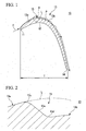
- FIGS. 1 to 3 An Embodiment of the present invention shall be described with reference to FIGS. 1 to 3 .
- a blade 10 in accordance with the present embodiment is configured so as to be surrounded by: a leading edge portion 11, which is where fluid F flows in; a pressure surface 12 which is a concave curve shape concaved along a direction the fluid F flows; a suction surface 13 which is a convex curve shape convexed along a direction the fluid F flows; and a trailing edge portion 14, which is where the fluid F flows out.
- the blade 10 is a turbine blade.
- a mounting stage 16 (not shown) for mounting the turbine blade on a main body of the turbine is provided on a side surface of the blade 10.
- a disturbance addition portion 15 is provided on the suction surface 13 closer to the leading edge portion 11 than a maximum velocity point P, where the flow velocity of the fluid F is maximized on the suction surface 13, for disturbing a laminar flow on the suction surface 13 and for transitioning to the turbulent flow.
- the disturbance addition portion 15 of the present embodiment is concaved in a thickness direction of the blade 10 formed by the pressure surface 12 and the suction surface 13 and is formed in a step portion extending along the direction the fluid F flows.
- a first suction surface 13a located in the leading edge portion 11 and a second suction surface 13b located in the trailing edge portion 14 are connected via the step portion.
- the second suction surface 13b is located closer to the pressure surface 12 than an imaginary curve L which is made when the first suction surface 13a is extended to the trailing edge portion 14 along the second suction surface 13b.
- the disturbance addition portion 15 is provided so as to extend in a blade height direction, that is, a direction perpendicular to a direction the fluid F flows on the suction surface 13.
- the disturbance addition portion 15 is provided so as to extend over the whole area in the blade height direction on the suction surface 13.
- the maximum velocity point P is generally located in the vicinity of a throat portion of the blade 10.
- the disturbance addition portion 15 is configured so that a connection portion 13c with the first suction surface 13a is a convex curve shape convexed toward the flow direction of the fluid F and a connection portion 13d with the second suction surface 13b is a concave curve shape concaved toward a reverse direction to the flow direction of the fluid F.
- An inclined surface 13e extending along the flow direction of the fluid F is configured between the connection portions 13c and 13d.
- an inclination angle ⁇ of the inclined surface 13e relative to the first suction surface 13a is set so as not to allow a part of the fluid F remain stagnant at the disturbance addition portion 15 or so as to transition from the laminar flow to the turbulent flow relative to the fluid F on the second suction surface 13b.
- the fluid F passing through the disturbance addition portion 15 smoothly flows onto the second suction surface 13b by the convex curve shape of the connection portion 13d with the second suction surface 13b.
- the fluid F flown onto the second suction surface 13b transitions to the turbulent flow with the laminar flow on the first suction surface 13a being disturbed.
- the suction surface 13 has the first suction surface 13a and the second suction surface 13b, and the first suction surface 13a and the second suction surface 13b are connected via the step portion which is the disturbance addition portion 15.
- the fluid F flown in from the leading edge portion 11 flows onto the first suction surface 13a reaches disturbance addition portion 15 and moves toward the second suction surface 13b by rapidly decelerating the fluid F after rapidly accelerating the fluid F in the disturbance addition portion 15, it is possible to disturb the laminar flow on the first suction surface 13a and transition to the turbulent flow on the second suction surface 13b.
- the disturbance addition portion 15 is configured to be a step portion so as to be extended along the flow direction of the fluid F and is continued to the second suction surface 13b. Accordingly, it is possible to prevent the part of the fluid F passing through the disturbance addition portion 15 from remaining stagnant in the disturbance addition portion 15; thereby, it is possible to make the fluid F smoothly flow onto the second suction surface 13b in the turbulent flow state after the transition. Therefore, it is possible to control the amount of energy loss due to the transition from the laminar flow to the turbulent flow in the minimum level.
- step portion which is the disturbance addition portion 15, on the suction surface 13 to provide the first suction surface 13a and the second suction surface 13b
- the step portion which is the disturbance addition portion 15
- the suction surface 13 to provide the first suction surface 13a and the second suction surface 13b
- the blade 10 when the blade 10 is made by casting, for example, a Lost wax casting process, together with the disturbance addition portion 15 be provided so as to extend over the whole area in the blade height direction on the suction surface 13, such restrictions in manufacturing conditions can be further reliably decreased.
- connection portion 13c between the disturbance addition portion 15 and the first suction surface 13a is formed as the convex curve shape and the connection portion 13d between the disturbance addition portion 15 and the second suction surface 13b is formed as the concave curve shape, they can be formed as an angled portion. In this case as well, substantially the same effect as described above can be obtained. Also, the blade in the present invention can be applied both to a rotor blade and a guide vane.
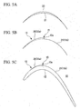
- FIGS. 5A to 5C show a design method (overview of the manufacturing method) of the blade 10 in accordance with the embodiment of the present invention, in particular, a design method for the suction surface 13 of the blade 10.
- a conventional airfoil (original airfoil) 21 and a modified airfoil 20, which has a modified figure relative to the conventional airfoil 21 with a larger curvature than the conventional airfoil 21, are prepared.
- the modified airfoil 20 is overlapped by the conventional airfoil 21.
- a rear portion of the modified airfoil 20 is deleted.
- a connection portion which is the inclined surface 13e of the disturbance addition portion 15
- the suction surface 13 of the blade 10 in accordance with the embodiment of the present invention is designed. Accordingly, the modified airfoil 21 becomes the first suction surface 13a and the conventional airfoil 21 becomes the second suction surface 13b.
- the blade 10 in accordance with the embodiment of the present invention designed in this manner is configured such that, as shown in FIG. 5C , the pressure surface 12 is the conventional airfoil (original airfoil) and a fore portion (the first suction surface 13a) of the suction surface 13 is the modified airfoil 20 and the rear portion (second suction surface 13b) of the suction surface 13 is the conventional airfoil 21.
- the modified airfoil 20 in the fore side and the conventional airfoil 21 in the rear side are connected by the inclined surface 13e which is the connection portion.
- FIG. 6 shows the fluid F flow around the blade 100 (original airfoil) in accordance with the conventional example.
- the fluid F flown in from a leading edge portion 110 onto a suction surface 130, causes a laminar separation, which is a phenomenon where the boundary layer separates in a trailing edge portion 140.
- FIG. 7 shows the fluid F flow around the blade 10 in accordance with the embodiment of the present invention.
- the fluid F flown in from the leading edge portion 11 flows onto the first suction surface 13a, reaches the disturbance addition portion 15, and moves toward the second suction surface 13b, the fluid F is rapidly decelerated after being rapidly accelerated in the step portion, which is the disturbance addition portion 15.
- the laminar flow on the first suction surface 13a is disturbed and transitions to the turbulent flow and is flown onto the trailing edge portion 14. Therefore, with the blade 10 in accordance with the embodiment of the present invention, the laminar separation does not occur in the fluid F on the trailing edge portion 14.
- FIG. 8A is a partially enlarged view showing from the leading edge portion 11 to the disturbance addition portion 15 of the blade 10 in accordance with the embodiment of the present invention.
- the pressure surface 12 is the conventional airfoil (original airfoil) and the fore portion (the first suction surface 13a) continued from the leading edge portion 11 of the suction surface 13 is the modified airfoil 20 and the rear portion (second suction surface 13b) of the suction surface 13 is the conventional airfoil 21.
- the modified airfoil 20 in the fore side and the original airfoil 21 in the rear side are connected by the inclined surface 13e which is the connection portion.
- FIG 8B shows a gap height ⁇ (gap amount, height of the disturbance addition portion) of the blade 10 in accordance with the embodiment of the present invention.
- the gap height ⁇ is a distance between the suction surface 13 and the conventional airfoil 21 (second suction surface 13b) when a line is drawn perpendicularly from an intersection (connection portion) 13c, which is between the modified airfoil 20 on the fore side (first suction surface 13a) of the suction surface 13 and the inclined surface 13e which is the connection portion, to the conventional airfoil 21 (second suction surface 13b).
- the gap height ⁇ as defined above is defined as 0.1 % to 10.0 % relative to an actual chord length R which is described later.
- chord length R shall be defined as below.
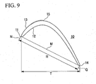
- the actual chord length R is a distance between a line N and a line Q, which are tangent to the leading edge portion 11 and the trailing edge portion 14 respectively, and are among a plurality of lines perpendicular to a tangential line M connecting the leading edge portion 11 and the trailing edge portion 14.
- FIG 8C shows a gap angle ⁇ (inclined surface angle) and a gap length ⁇ (inclined surface length) of the blade 10 in accordance with the embodiment of the present invention.
- the gap angle P is an angle between the inclined surface 13e and a vertical line drawn from an intersection (connection portion) 13c, which is between the modified airfoil 20 on the front side (first suction surface 13a) of the suction surface 13 and the inclined surface 13e which is the connection portion, to the pressure surface 12.
- the gap angle ⁇ is set between 20° to 85° in order not to allow the part of the fluid remain stagnant in the disturbance addition portion 15 or to be able to transition relative to the fluid from the laminar flow to the turbulent flow on the second suction surface 13b.
- the gap length ⁇ is a length of the inclined surface 13e between the intersection 13c and an intersection (connection portion) 13d, in which the intersection 13c is between the modified airfoil 20 on the fore side (first suction surface 13a) of the suction surface 13 and the inclined surface 13e, which is the connection portion, and the intersection 13d is between the second suction surface 13b and the inclined surface 13e. That is, the gap length ⁇ is the length of the inclined surface 13e.
- the gap length ⁇ is set to 0.2 % to 20 % relative to the whole length of the blade 10 along the suction surface 13 from a leading end of the leading edge portion 11 to a posterior end of the trailing edge portion 14.
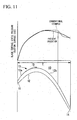
- a verification test is performed relative to a blade surface velocity and a blade surface static pressure on the suction surface 13 of the blade 10 in accordance with the embodiment of the present invention.
- a disturbance addition portion 15 is provided on the suction surface 13 closer to the leading edge portion 11 than a maximum velocity point P, where the flow velocity of the fluid is maximized on the suction surface 13, for disturbing a laminar flow on the suction surface 13 and for transitioning to a turbulent flow.
- the fluid flown onto the suction surface 13 is rapidly decelerated after being rapidly accelerated in the step portion, which is the disturbance addition portion 15, located closer to the leading edge portion 11 than a maximum velocity point P.
- the laminar separation or a reattachment of the fluid is caused on the second suction surface, the static pressure changes rapidly.
- the laminar separation of the fluid is not caused even on the second suction surface 13b, it is understood that the static pressure changes smoothly.
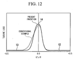
- FIG. 12 shows graphs showing the turbine loss of the blade 10 in accordance with the embodiment of the present invention and the blade in accordance with the conventional example.
- FIG. 13 shows a pitch shown in the horizontal axis of FIG. 12 . That is, the pitch shown in the horizontal axis of FIG. 12 is defined so that, as shown in FIG. 13 , when a trailing edge portion 14a of one blade 10a is defined as 0.0 pitch, a trailing edge portion 14b of another blade 10b adjacent to a suction surface of the blade 10a is defined as -1.0 pitch relative to the blade 10a, and a trailing edge portion 14c of another blade 10c adjacent to a pressure surface of the blade 10a is defined as +1.0 pitch relative to the blade 10a.
- an intermediate position between the trailing edge portion 14a of the blade 10a and the trailing edge portion 14b of the blade 10b is defined as -0.5 pitch and an intermediate position between the trailing edge portion 14a of the blade 10a and the trailing edge portion 14c of the blade 10c is defined as +0.5 pitch.
- the turbine loss is improved by approximately 10 % compared to the blade in accordance with the conventional example.
- the turbine loss is small which means the turbine loss is improved.
- the laminar separation on the suction surface 13 is prevented, the fluid flow on the suction surface 13 is smooth, a pressure loss on a blade exit on the suction surface 13 is small, and the turbine loss is improved by approximately 10 % as shown in the graph of FIG 12 .
- a blade is provided for preventing a laminar separation from occurring on a trailing edge portion of a suction surface without causing restrictions on manufacturing conditions.
Landscapes
- Engineering & Computer Science (AREA)
- Mechanical Engineering (AREA)
- General Engineering & Computer Science (AREA)
- Physics & Mathematics (AREA)
- Fluid Mechanics (AREA)
- Structures Of Non-Positive Displacement Pumps (AREA)
- Turbine Rotor Nozzle Sealing (AREA)
Claims (1)
- Pale (10) comprenant:une partie de bord d'attaque (11), qui est la partie avant dans le sens de l'écoulement d'un fluide (F) ;une surface de pression (12), qui est une forme à courbe concave rendue concave dans le sens de l'écoulement du fluide (F) ;une surface d'aspiration (13) qui est une forme à courbe convexe rendue convexe dans le sens de l'écoulement du fluide (F) ; etune partie de bord de fuite (14), qui est la partie arrière dans le sens de l'écoulement du fluide (F), dans laquelleune partie d'ajout de turbulence (15) est prévue sur la surface d'aspiration (13) plus à proximité de la partie de bord d'attaque qu'un point de vitesse maximale (P), où la vitesse d'écoulement du fluide (F) est maximalisée sur la surface d'aspiration (13), afin de perturber un écoulement laminaire sur la surface d'aspiration (13) et de passer à un écoulement turbulent, dans laquelle :la partie d'ajout de turbulence (15) est rendue concave dans le sens de l'épaisseur de la pale (10) formée par la surface de pression (12) et la surface d'aspiration (13), et constituée par une partie en gradin qui s'étend dans le sens de l'écoulement du fluide (F),sur la surface d'aspiration (13), une première surface d'aspiration (13a) située dans la partie de bord d'attaque (11) et une seconde surface d'aspiration (13b) située dans la partie de bord de fuite (14) sont reliées par la partie en gradin,la seconde surface d'aspiration (13b) est située plus à proximité de la surface de pression (12) qu'une courbe imaginaire (L) qui est créée lorsque la première surface d'aspiration (13a) est prolongée sur le côté de la partie de bord de fuite (14) le long de la seconde surface d'aspiration (13b),la partie d'ajout de turbulence (15) comporte une partie de liaison (13c) qui relie la partie d'ajout de turbulence (15) à la première surface d'aspiration (13a), la partie de liaison (13c) étant une forme à courbe convexe rendue convexe vers le sens d'écoulement du fluide (F), etla partie d'ajout de turbulence (15) est prévue de manière à s'étendre sur la totalité de la surface dans le sens de la hauteur de la pale sur la surface d'aspiration (13).
Applications Claiming Priority (2)
| Application Number | Priority Date | Filing Date | Title |
|---|---|---|---|
| JP2006113537 | 2006-04-17 | ||
| PCT/JP2007/057756 WO2007119696A1 (fr) | 2006-04-17 | 2007-04-06 | Pale |
Publications (3)
| Publication Number | Publication Date |
|---|---|
| EP2019186A1 EP2019186A1 (fr) | 2009-01-28 |
| EP2019186A4 EP2019186A4 (fr) | 2012-09-26 |
| EP2019186B1 true EP2019186B1 (fr) | 2016-01-06 |
Family
ID=38609457
Family Applications (1)
| Application Number | Title | Priority Date | Filing Date |
|---|---|---|---|
| EP07741192.4A Active EP2019186B1 (fr) | 2006-04-17 | 2007-04-06 | Pale |
Country Status (5)
| Country | Link |
|---|---|
| US (1) | US8118560B2 (fr) |
| EP (1) | EP2019186B1 (fr) |
| JP (1) | JPWO2007119696A1 (fr) |
| CA (1) | CA2649799C (fr) |
| WO (1) | WO2007119696A1 (fr) |
Families Citing this family (22)
| Publication number | Priority date | Publication date | Assignee | Title |
|---|---|---|---|---|
| GB0910647D0 (en) | 2009-06-22 | 2009-08-05 | Rolls Royce Plc | A compressor blade |
| EP2369133B1 (fr) * | 2010-03-22 | 2015-07-29 | Rolls-Royce Deutschland Ltd & Co KG | Aube pour turbomachine |
| DE102010021925A1 (de) * | 2010-05-28 | 2011-12-01 | Mtu Aero Engines Gmbh | Schaufel einer Strömungsmaschine mit passiver Grenzschichtbeeinflussung |
| DE102011083778A1 (de) * | 2011-09-29 | 2013-04-04 | Rolls-Royce Deutschland Ltd & Co Kg | Schaufel einer Rotor- oder Statorreihe für den Einsatz in einer Strömungsmaschine |
| CN102587998B (zh) * | 2012-02-24 | 2014-04-02 | 西北工业大学 | 一种用于控制气流分离的叶片吸力面凹槽的设计方法 |
| US9957801B2 (en) * | 2012-08-03 | 2018-05-01 | United Technologies Corporation | Airfoil design having localized suction side curvatures |
| CN104420888B (zh) * | 2013-08-19 | 2016-04-20 | 中国科学院工程热物理研究所 | 渐缩流道跨音速涡轮叶片及应用其的涡轮 |
| CN104314618B (zh) * | 2014-10-09 | 2015-08-19 | 中国科学院工程热物理研究所 | 一种低压涡轮叶片结构及降低叶片损失的方法 |
| CN104527956A (zh) * | 2015-01-23 | 2015-04-22 | 朱晓义 | 一种水中动力装置 |
| US11933323B2 (en) * | 2015-07-23 | 2024-03-19 | Onesubsea Ip Uk Limited | Short impeller for a turbomachine |
| US10934847B2 (en) * | 2016-04-14 | 2021-03-02 | Mitsubishi Power, Ltd. | Steam turbine rotor blade, steam turbine, and method for manufacturing steam turbine rotor blade |
| US10935041B2 (en) * | 2016-06-29 | 2021-03-02 | Rolls-Royce Corporation | Pressure recovery axial-compressor blading |
| US10519976B2 (en) * | 2017-01-09 | 2019-12-31 | Rolls-Royce Corporation | Fluid diodes with ridges to control boundary layer in axial compressor stator vane |
| US10766544B2 (en) * | 2017-12-29 | 2020-09-08 | ESS 2 Tech, LLC | Airfoils and machines incorporating airfoils |
| FR3081497B1 (fr) * | 2018-05-23 | 2020-12-25 | Safran Aircraft Engines | Aubage brut de fonderie a geometrie de bord de fuite modifiee |
| BE1026579B1 (fr) * | 2018-08-31 | 2020-03-30 | Safran Aero Boosters Sa | Aube a protuberance pour compresseur de turbomachine |
| US20200232330A1 (en) * | 2019-01-18 | 2020-07-23 | United Technologies Corporation | Fan blades with recessed surfaces |
| CN113586163B (zh) * | 2021-07-05 | 2023-09-19 | 浙江理工大学 | 一种具有主动射流结构的壁面滚动式叶片 |
| CN113847277B (zh) * | 2021-10-17 | 2023-06-23 | 西北工业大学 | 吸力面有波纹凹槽的超声速多孔吸附式压气机叶片 |
| US12415615B2 (en) | 2023-02-23 | 2025-09-16 | ESS 2 Tech, LLC | Fluid accelerator |
| US12409945B2 (en) | 2023-02-23 | 2025-09-09 | ESS 2 Tech, LLC | Fluid accelerator |
| US12503249B2 (en) | 2023-02-23 | 2025-12-23 | ESS 2 Tech, LLC | Ram air turbine |
Family Cites Families (23)
| Publication number | Priority date | Publication date | Assignee | Title |
|---|---|---|---|---|
| DE82803C (fr) * | ||||
| FR500042A (fr) * | 1918-05-27 | 1920-02-28 | Hans Georg Garde | Perfectionnements aux ailes d'hélice |
| US2166823A (en) * | 1937-10-19 | 1939-07-18 | Gen Electric | Elastic fluid turbine nozzle |
| GB580806A (en) * | 1941-05-21 | 1946-09-20 | Alan Arnold Griffith | Improvements in compressor, turbine and like blades |
| GB750305A (en) * | 1953-02-05 | 1956-06-13 | Rolls Royce | Improvements in axial-flow compressor, turbine and like blades |
| US3014640A (en) * | 1958-06-09 | 1961-12-26 | Gen Motors Corp | Axial flow compressor |
| US3000401A (en) | 1960-01-29 | 1961-09-19 | Friedrich O Ringleb | Boundary layer flow control device |
| GB2032048A (en) | 1978-07-15 | 1980-04-30 | English Electric Co Ltd | Boundary layer control device |
| JPS5666494A (en) | 1979-11-02 | 1981-06-04 | Hitachi Ltd | Impeller for centrifugal compressor |
| DE3325663C2 (de) * | 1983-07-15 | 1985-08-22 | MTU Motoren- und Turbinen-Union München GmbH, 8000 München | Axial durchströmtes Schaufelgitter einer mit Gas oder Dampf betriebenen Turbine |
| JPH0224290A (ja) * | 1988-07-13 | 1990-01-26 | Nkk Corp | 低抵杭水中翼 |
| JPH0711901A (ja) * | 1993-06-29 | 1995-01-13 | Ishikawajima Harima Heavy Ind Co Ltd | はく離制御翼 |
| JPH08296402A (ja) * | 1995-04-25 | 1996-11-12 | Ishikawajima Harima Heavy Ind Co Ltd | ファン及び圧縮機の動翼 |
| ATE200139T1 (de) * | 1995-12-12 | 2001-04-15 | Roche Ulrich | Verfahren zur ausbildung einer oberfläche für den kontakt mit einem strömenden fluid und körper mit entsprechend ausgebildeten oberflächenbereichen |
| JP2000104501A (ja) | 1998-09-28 | 2000-04-11 | Hitachi Ltd | タービン動翼及びガスタービン及び蒸気タービン |
| JP2000337101A (ja) * | 1999-05-28 | 2000-12-05 | Mitsubishi Heavy Ind Ltd | 軸流タービン翼列 |
| JP3738155B2 (ja) | 1999-07-21 | 2006-01-25 | 三洋電機株式会社 | 軸流送風機 |
| GB9920564D0 (en) * | 1999-08-31 | 1999-11-03 | Rolls Royce Plc | Axial flow turbines |
| JP2002021502A (ja) | 2000-07-04 | 2002-01-23 | Senshin Zairyo Riyo Gas Generator Kenkyusho:Kk | 翼列圧力損失低減装置 |
| US7878759B2 (en) * | 2003-12-20 | 2011-02-01 | Rolls-Royce Deutschland Ltd & Co Kg | Mitigation of unsteady peak fan blade and disc stresses in turbofan engines through the use of flow control devices to stabilize boundary layer characteristics |
| DE502004002003D1 (de) | 2004-03-25 | 2006-12-28 | Rolls Royce Deutschland | Verdichter für ein Flugzeugtriebwerk |
| KR100669731B1 (ko) | 2004-10-12 | 2007-01-16 | 삼성에스디아이 주식회사 | 플라즈마 디스플레이 장치 |
| US7685713B2 (en) * | 2005-08-09 | 2010-03-30 | Honeywell International Inc. | Process to minimize turbine airfoil downstream shock induced flowfield disturbance |
-
2007
- 2007-04-06 WO PCT/JP2007/057756 patent/WO2007119696A1/fr not_active Ceased
- 2007-04-06 CA CA2649799A patent/CA2649799C/fr active Active
- 2007-04-06 EP EP07741192.4A patent/EP2019186B1/fr active Active
- 2007-04-06 JP JP2008510941A patent/JPWO2007119696A1/ja active Pending
- 2007-04-06 US US12/297,256 patent/US8118560B2/en active Active
Also Published As
| Publication number | Publication date |
|---|---|
| EP2019186A4 (fr) | 2012-09-26 |
| CA2649799A1 (fr) | 2007-10-25 |
| US20090136354A1 (en) | 2009-05-28 |
| WO2007119696A1 (fr) | 2007-10-25 |
| EP2019186A1 (fr) | 2009-01-28 |
| CA2649799C (fr) | 2011-09-13 |
| JPWO2007119696A1 (ja) | 2009-08-27 |
| US8118560B2 (en) | 2012-02-21 |
Similar Documents
| Publication | Publication Date | Title |
|---|---|---|
| EP2019186B1 (fr) | Pale | |
| US7063508B2 (en) | Turbine rotor blade | |
| EP1798377B1 (fr) | Aube avec profilés de charge différents le long de l'envergure | |
| EP2333242B1 (fr) | Contrôle de vortex de l'extrémité sur une aube de rotor pour un moteur à turbine à gaz | |
| EP1995410B1 (fr) | Paroi de bout de grille d'aubes de turbine | |
| EP2460978B1 (fr) | Aube de guidage à géométrie variable | |
| US8152459B2 (en) | Airfoil for axial-flow compressor capable of lowering loss in low Reynolds number region | |
| US6638021B2 (en) | Turbine blade airfoil, turbine blade and turbine blade cascade for axial-flow turbine | |
| EP1260674B1 (fr) | Turbine et aube de turbine | |
| EP2096320B1 (fr) | Grille d'aubes de compresseur axial | |
| US9670783B2 (en) | Blade of a turbomachine, having passive boundary layer control | |
| EP2703600B1 (fr) | Aube de turbine | |
| EP2211020A1 (fr) | Pale de turbine ou vanne avec refroidissement amélioré | |
| JP2010203409A (ja) | 流体機械用翼体 | |
| US6527510B2 (en) | Stator blade and stator blade cascade for axial-flow compressor | |
| US6802474B2 (en) | Advanced high turning compressor airfoils | |
| JP2002349201A (ja) | タービン動翼 | |
| JPH08121390A (ja) | 高速流体用の圧縮機翼形 | |
| JPS6139482B2 (fr) |
Legal Events
| Date | Code | Title | Description |
|---|---|---|---|
| PUAI | Public reference made under article 153(3) epc to a published international application that has entered the european phase |
Free format text: ORIGINAL CODE: 0009012 |
|
| 17P | Request for examination filed |
Effective date: 20081104 |
|
| AK | Designated contracting states |
Kind code of ref document: A1 Designated state(s): AT BE BG CH CY CZ DE DK EE ES FI FR GB GR HU IE IS IT LI LT LU LV MC MT NL PL PT RO SE SI SK TR |
|
| AX | Request for extension of the european patent |
Extension state: AL BA HR MK RS |
|
| RBV | Designated contracting states (corrected) |
Designated state(s): DE FR GB IT |
|
| DAX | Request for extension of the european patent (deleted) | ||
| A4 | Supplementary search report drawn up and despatched |
Effective date: 20120827 |
|
| RIC1 | Information provided on ipc code assigned before grant |
Ipc: F01D 5/14 20060101AFI20120821BHEP |
|
| GRAP | Despatch of communication of intention to grant a patent |
Free format text: ORIGINAL CODE: EPIDOSNIGR1 |
|
| RIC1 | Information provided on ipc code assigned before grant |
Ipc: F01D 5/14 20060101AFI20150529BHEP |
|
| INTG | Intention to grant announced |
Effective date: 20150624 |
|
| GRAS | Grant fee paid |
Free format text: ORIGINAL CODE: EPIDOSNIGR3 |
|
| GRAA | (expected) grant |
Free format text: ORIGINAL CODE: 0009210 |
|
| AK | Designated contracting states |
Kind code of ref document: B1 Designated state(s): DE FR GB IT |
|
| REG | Reference to a national code |
Ref country code: GB Ref legal event code: FG4D |
|
| REG | Reference to a national code |
Ref country code: DE Ref legal event code: R096 Ref document number: 602007044454 Country of ref document: DE |
|
| REG | Reference to a national code |
Ref country code: FR Ref legal event code: PLFP Year of fee payment: 10 |
|
| REG | Reference to a national code |
Ref country code: DE Ref legal event code: R097 Ref document number: 602007044454 Country of ref document: DE |
|
| PLBE | No opposition filed within time limit |
Free format text: ORIGINAL CODE: 0009261 |
|
| STAA | Information on the status of an ep patent application or granted ep patent |
Free format text: STATUS: NO OPPOSITION FILED WITHIN TIME LIMIT |
|
| 26N | No opposition filed |
Effective date: 20161007 |
|
| REG | Reference to a national code |
Ref country code: FR Ref legal event code: PLFP Year of fee payment: 11 |
|
| REG | Reference to a national code |
Ref country code: FR Ref legal event code: PLFP Year of fee payment: 12 |
|
| PGFP | Annual fee paid to national office [announced via postgrant information from national office to epo] |
Ref country code: DE Payment date: 20250305 Year of fee payment: 19 |
|
| PGFP | Annual fee paid to national office [announced via postgrant information from national office to epo] |
Ref country code: GB Payment date: 20260313 Year of fee payment: 20 |
|
| PGFP | Annual fee paid to national office [announced via postgrant information from national office to epo] |
Ref country code: IT Payment date: 20260320 Year of fee payment: 20 |
|
| PGFP | Annual fee paid to national office [announced via postgrant information from national office to epo] |
Ref country code: FR Payment date: 20260309 Year of fee payment: 20 |