EP2019226A2 - Agencement d'accouplement - Google Patents
Agencement d'accouplement Download PDFInfo
- Publication number
- EP2019226A2 EP2019226A2 EP08160055A EP08160055A EP2019226A2 EP 2019226 A2 EP2019226 A2 EP 2019226A2 EP 08160055 A EP08160055 A EP 08160055A EP 08160055 A EP08160055 A EP 08160055A EP 2019226 A2 EP2019226 A2 EP 2019226A2
- Authority
- EP
- European Patent Office
- Prior art keywords
- friction
- flow
- fluid
- profiling
- coupling arrangement
- Prior art date
- Legal status (The legal status is an assumption and is not a legal conclusion. Google has not performed a legal analysis and makes no representation as to the accuracy of the status listed.)
- Granted
Links
Images


Classifications
-
- F—MECHANICAL ENGINEERING; LIGHTING; HEATING; WEAPONS; BLASTING
- F16—ENGINEERING ELEMENTS AND UNITS; GENERAL MEASURES FOR PRODUCING AND MAINTAINING EFFECTIVE FUNCTIONING OF MACHINES OR INSTALLATIONS; THERMAL INSULATION IN GENERAL
- F16D—COUPLINGS FOR TRANSMITTING ROTATION; CLUTCHES; BRAKES
- F16D25/00—Fluid-actuated clutches
- F16D25/12—Details not specific to one of the before-mentioned types
- F16D25/123—Details not specific to one of the before-mentioned types in view of cooling and lubrication
-
- F—MECHANICAL ENGINEERING; LIGHTING; HEATING; WEAPONS; BLASTING
- F16—ENGINEERING ELEMENTS AND UNITS; GENERAL MEASURES FOR PRODUCING AND MAINTAINING EFFECTIVE FUNCTIONING OF MACHINES OR INSTALLATIONS; THERMAL INSULATION IN GENERAL
- F16D—COUPLINGS FOR TRANSMITTING ROTATION; CLUTCHES; BRAKES
- F16D13/00—Friction clutches
- F16D13/58—Details
- F16D13/70—Pressure members, e.g. pressure plates, for clutch-plates or lamellae; Guiding arrangements for pressure members
-
- F—MECHANICAL ENGINEERING; LIGHTING; HEATING; WEAPONS; BLASTING
- F16—ENGINEERING ELEMENTS AND UNITS; GENERAL MEASURES FOR PRODUCING AND MAINTAINING EFFECTIVE FUNCTIONING OF MACHINES OR INSTALLATIONS; THERMAL INSULATION IN GENERAL
- F16D—COUPLINGS FOR TRANSMITTING ROTATION; CLUTCHES; BRAKES
- F16D13/00—Friction clutches
- F16D13/58—Details
- F16D13/72—Features relating to cooling
-
- F—MECHANICAL ENGINEERING; LIGHTING; HEATING; WEAPONS; BLASTING
- F16—ENGINEERING ELEMENTS AND UNITS; GENERAL MEASURES FOR PRODUCING AND MAINTAINING EFFECTIVE FUNCTIONING OF MACHINES OR INSTALLATIONS; THERMAL INSULATION IN GENERAL
- F16D—COUPLINGS FOR TRANSMITTING ROTATION; CLUTCHES; BRAKES
- F16D25/00—Fluid-actuated clutches
- F16D25/06—Fluid-actuated clutches in which the fluid actuates a piston incorporated in, i.e. rotating with the clutch
- F16D25/062—Fluid-actuated clutches in which the fluid actuates a piston incorporated in, i.e. rotating with the clutch the clutch having friction surfaces
- F16D25/063—Fluid-actuated clutches in which the fluid actuates a piston incorporated in, i.e. rotating with the clutch the clutch having friction surfaces with clutch members exclusively moving axially
- F16D25/0635—Fluid-actuated clutches in which the fluid actuates a piston incorporated in, i.e. rotating with the clutch the clutch having friction surfaces with clutch members exclusively moving axially with flat friction surfaces, e.g. discs
- F16D25/0638—Fluid-actuated clutches in which the fluid actuates a piston incorporated in, i.e. rotating with the clutch the clutch having friction surfaces with clutch members exclusively moving axially with flat friction surfaces, e.g. discs with more than two discs, e.g. multiple lamellae
-
- F—MECHANICAL ENGINEERING; LIGHTING; HEATING; WEAPONS; BLASTING
- F16—ENGINEERING ELEMENTS AND UNITS; GENERAL MEASURES FOR PRODUCING AND MAINTAINING EFFECTIVE FUNCTIONING OF MACHINES OR INSTALLATIONS; THERMAL INSULATION IN GENERAL
- F16D—COUPLINGS FOR TRANSMITTING ROTATION; CLUTCHES; BRAKES
- F16D48/00—External control of clutches
- F16D48/02—Control by fluid pressure
- F16D2048/0212—Details of pistons for primary or secondary cylinders especially adapted for fluid control
Definitions
- the invention relates to a coupling arrangement according to the preamble of claim 1.
- a coupling arrangement for a motor vehicle which comprises a fluid-filled medium clutch housing.
- the clutch housing receives some rotatable first with the clutch housing friction elements and some rotatable with an output member second friction elements, which are engageable by means of a piston-shaped pressing member for producing a friction interaction in operative connection with each other, and together form a friction clutch.
- At least one first friction element and at least one second friction element are each provided with a fluid conveying surface for generating a fluid circulation flowing around the friction elements at least in regions.
- the first friction elements are due to their connection to the clutch housing and thus with the drive side in traction with a operated higher speed than the second friction elements, which are rotationally fixed to the output side.
- a flow circulation is generated which urges radially outward in the region of the friction elements, there via the axial flow passages by means of a substantially axial flow to the adjacent friction element lower rotational speed arrive there to be pushed back radially inward due to the difference in speed where it flows through the flow passages back to the friction element higher speed.
- the invention has the object of providing a coupling device in such a way that regardless of the operating condition always a sufficient cooling effect is available.
- FIG. 6 The drawing is the profiling 114 of the corresponding surface of the pressing member 32 with a substantially radially extending grooving 116th educated.
- the radially outer end 130 of the groove 116 is located on the radially outer radius r a , the radially inner end 132 of the groove 116, however, on the radially inner radius r i .
- the total flow velocity c a are also greater than the corresponding flow velocities ui, ⁇ i and ci at the radially inner radius ri.
- Fig. 7 an example in that the grooving 116 is arcuate despite at least substantially radial extension direction.
- the course of the groove 116 is in this case selected such that its radially inner end 132 is aligned against the direction of rotation ⁇ , while the radially outer end 130 is aligned in the direction of rotation ⁇ . Due to this alignment of the two radial ends 130, 132 of the groove 128, the radially inner tangential flow velocity c i decreases in relation to that in FIG Fig.
- such a profiling can also be provided on an additional flow guide element, the flow guide element preferably having a profiled side of the contact pressure element and the friction elements of the Friction clutch is provided.
- the Stömungsleitelement can limit together with the pressing a flow channel, which not only returns fluid medium, which originates from the friction elements of the friction clutch, to these friction elements, but also passes the clutch housing freshly supplied fluid medium to the friction elements.
- the flow guide is provided with a profiling which serves at least a first flow passage for supplied from a fluid source, fresh fluid medium, and at least a second flow passage for originating from the friction elements of the friction clutch fluid-shaped medium.
- the profiling of the flow-guiding element is provided on its side facing the pressing-on element, and thus can supplement or even replace the profiling of the pressing-on element.
- the profiling has at least one groove with an extension direction extending at least substantially in the radial direction, whereby this groove can extend essentially radially, or with components in the circumferential direction, in particular at its radial ends.
- Fig. 1 is a drive train 1 with a coupling arrangement 3 according to the invention shown schematically.
- the coupling arrangement 3 comprises a coupling housing 5, which can be coupled to a drive shaft 11, for example the crankshaft of an internal combustion engine 13, for common rotation via a plurality of fastening elements 7 and a coupling element 9, such as a flex plate, and, as in FIG Fig. 2 clearly shown, in the region of a rotation axis 55 has a bearing pin 10, which is received in a formed on the output shaft 11 centering guide 12.
- the clutch housing 5 has a housing hub 15, which is connected to a gear arrangement 17, for example, and drives a fluid supply pump (not shown) for rotation there.
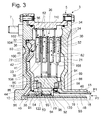
- Concentrically arranged to the housing hub 15 is an in Fig. 3 shown output member 18 which projects with its free end into the coupling housing 5.
- This output member 18 may be, for example, a transmission input shaft 19.
- the clutch housing 5 has a drive-side housing wall 20 extending substantially radially outward from the bearing journal 10 and a drive-side housing wall 21 extending essentially radially outward from the housing hub 15. These two housing walls 20, 21 each take in the radially outer region a housing outer shell 56 which axially connects the two housing walls 20, 21 together.
- the clutch housing 5 encloses a fluid chamber 34 filled with a fluid medium.
- first friction elements 22 which are coupled to the clutch housing 5 and in particular with its effective as drive side Reibelementenarme 110 housing outer shell 56 for common rotation, and a plurality of second friction elements 24, which via an output hub 28 of a driven-side Reibelementenlies 112 are coupled to the transmission input shaft 19 as a driven member 18 for common rotation provided.
- the friction elements 22, 24 together with the friction element carriers 110, 112 form a friction clutch 26.
- the output-side friction element carrier 112 is supported on the output side via a first axial bearing 84 with flow passages 88 on the output-side housing wall 21 and on the drive side via a second axial bearing 86 with flow passages 90 on a contact-pressure carrier 39 fixedly connected to the drive-side housing wall 20.
- This serves together with a pressing member 32, which forms a coupling device 40 together with the friction clutch 26, as a partition wall 40 between the fluid chamber 34 and an axially through the drive-side housing wall 20 and the partition wall 40 limited Beaufschlagungshunt 36 via fluid flow channels 44 and a connecting space 45th is connected to a central bore 38 of the transmission input shaft 19.
- the output-side thrust bearing 84 via its flow passages 88 has a flow connection with an annular flow space 48 of a first pressure circuit P1, wherein the annular flow space 48 radially between the housing hub 15 and a in the Substantially sleeve-shaped separating element 46 is provided.
- a substantially annular flow space 50 of a second pressure circuit P2 is provided.
- the annular flow space 50 opens directly into the output side radial flow passages 92 of the output side friction element support 112, but in contrast only indirectly, namely via an axial toothing 94 through which the rotationally fixed connection of the output hub 28 of the driven side Reibelementenlies 112 takes place with the transmission input shaft 19, in drive-side radial flow passages 93rd
- the radial flow passages 92, 93 are connected to each other via Axialströmungs disrupt 96 in the output side Reibelementenarme 112, the drive side opening into a flow passages 90 of the axial bearing 88 connecting chamber 91, and the output side as well as the output side radial flow passages 92 bounded by a seal 98 are the radially outward in contact with a driven-side axial projection 99 of the driven-side Reibelementen obviouslys 112 and / or the a Bend-side thrust bearing 84 is and radially inwardly in contact with the separating element 46th
- the annular flow space 48 of the first pressure circuit P1 is pressure-tightly separated from an extension portion 118 of the second pressure circuit P2, along a first connection 120 from the driven-side radial flow passages 92, the axial flow passages 96 and the connection chamber 91 and along a second connection 122 the axial gearing 94, the radial flow passages 93 and the connecting chamber 91.
- the first pressure circuit P1 is connected via the flow passages 88 of the output-side axial bearing 84 and the second pressure circuit P2 via the flow passages 90 of the drive-side axial bearing 86 to the fluid chamber 34.
- a third pressure circuit P3 comprises the central bore 38 of the transmission input shaft 19 and the connecting space 45 and the fluid flow channels 44 for connection to the loading chamber 36 for the pressing member 32, and causes under pressure a positive pressure in the loading chamber 36 against the fluid chamber 34 for engagement of the coupling device 40 by Conversely, a relief of the pressure circuit P3 causes an overpressure in the fluid chamber 34 with respect to the loading chamber 36, and thus an axial displacement of the contact pressure means 32 away from the friction elements 22, 24th for disengaging the coupling device 40.
- the pressure circuit P3 is isolated by a radially provided between a driven axial projection 53 of the journal 10 and the transmission input shaft 19 seal 54 relative to the pressure circuit P2, while not üb to the pressure circuit P1 he has a connection.
- the contact element 32 radially inwardly via a first Anpressaminendichtung 100 on Anpressaminenyour 39 and radially outside via a second Anpressaminendichtung 102 on a Anpressaminen Adjust 104 of the drive-side housing 20 in abutment.
- an abutment element 30 is provided on the output-side housing wall 21 on the sides of the friction elements 22, 24 facing away from this.
- the fluid chamber 34 can be supplied with a fluid medium, for example, by means of a fluid supply pump provided in the gear arrangement, through which the viscous medium is introduced via the first pressure circuit P1 into the fluid chamber 34, in which it flows radially outward.
- the fluid medium flows around the friction elements 22, 24 substantially axially, then passes radially inward and is withdrawn via the second pressure circuit P2 again. In this way, as described below, heated in the clutch housing 5 fluid medium can be continuously replaced and replaced by cooler fluid medium.
- fluid conveying surfaces 106, 108 are formed, which extend substantially axially and thereby cause an acceleration of fluid in the fluid chamber 34 when rotating about the axis of rotation 55.
- the fluid conveying surfaces 106 of the first friction elements 22 which are coupled to the clutch housing 5 for common rotation, for example in a coupling operation, in which the first friction elements 22 have a significantly higher speed than the second friction elements 24, as pump blade surfaces and provide the first Friction elements 22 in their function as a pump element 80 for the fact that in its area a radially outwardly guided fluid flow is generated.
- the second Friction elements 24 provided in a corresponding manner fluid conveying surfaces 108 as turbine blade surfaces and thus serve to form a turbine element 82.
- the latter is at an existing speed difference between the first friction elements 22 and the second friction elements 24 for the set by the fluid conveying surfaces 106 of the first friction elements 22 in fluid fluid by means of the fluid conveying surfaces 108 as torque support and thereby directs the fluid medium radially inward, where it replaces the through the fluid conveying surfaces 106 of the first friction elements 22 from radially inward to radially outward funded fluid medium.
- the fluid medium moved radially outward by the friction elements 22 of the pump element 80 is deflected axially there in the direction of the respectively adjacent friction element 22, 24.
- the fluidic medium passes through the friction elements 22, 24 axially.
- the fluid medium moved radially inward on the friction elements 24 of the turbine element 82 is also deflected there in the direction of the respectively adjacent friction element 22, 24, which can also be passed axially by the fluid medium.
- a fluid circulation which corresponds to the fluid circulation, as by a pump impeller and a Turbine wheel of a hydrodynamic torque converter or a hydraulic clutch is generated.
- the fluid circulation generated in the clutch assembly 3 causes, regardless of the aforementioned exchange of existing in the clutch housing 5 fluid medium, which fluid exchange can be done, for example, at a rate of 10 l / min, a permanent fluid circulation and flow around the friction elements 22, 24 which can produce, for example, a flow around these friction elements 22, 24 with a liquid volume of 3000 l / min.
- This fluid circulation is superimposed on the comparatively slow fluid exchange, so that the fluid medium brought to a comparatively high temperature by the circulation is always partially withdrawn and replaced by a cooler fluid medium.
- At least a portion of the first friction elements 22 and at least a portion of the second friction elements 24 carries on at least one axial side in each case a friction lining 52.
- These friction linings 52 are each a further friction element 22, 24 for reibrow Interaction axially opposite.
- the structural design of the friction elements 22, 24 is in detail on the above-mentioned, with respect to their disclosure content fully contained DE 101 25 628 A1 directed.
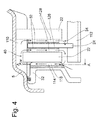
- Fig. 4 is the coupling device 40 enlarged drawn out.
- Fig. 4 Deviating from the illustration in Fig. 3 has the pressing member 32 in Fig. 4 a profiling 114 in the form of a groove 116 which, for example, as shown in the Fig. 6 or 7 may be formed, and extends with an at least significant extension component in the radial direction.
- the Fig. 6 or 7 clarify the in Fig. 4 indicated viewing direction A.
- the driven-side friction element 24 is formed with a lining carrier 126, which is equipped axially on both sides with friction linings 152. These are provided on their sides facing away from the lining carrier 126 sides with grooving 128.
- the flow through the coupling device 40 caused by the profiling 114 on the pressing element 32 is represented by arrows.
- the viscous medium is deflected on the drive-side friction element carrier 110 in an axial flow direction.
- the profiling 114 of the corresponding surface of the pressing element 32 is formed with a substantially radially extending Groove 116.
- the radially outer end 130 of the groove 116 is located on the radially outer radius r a , the radially inner end 132 of the groove 116, however, on the radially inner radius r i .
- the Total flow velocity c a each greater than the corresponding flow velocities u i , ⁇ i and c i at the radially inner radius r i .
- the groove 116 is arcuate despite at least substantially radial extension direction.
- the course of the groove 116 is in this case selected such that its radially inner end 132 is aligned against the direction of rotation ⁇ , the radially outer end 130, however, in the direction of rotation ⁇ . Due to this alignment of the two radial ends 130, 132 of the groove 128, the radially inner tangential flow velocity c i decreases in relation to that in FIG Fig. 6 while the radially outer tangential flow velocity c a is opposite that in FIG Fig. 6 Overall, this increases the gradient of the tangential flow velocity, and thus also the volume flow V s that can be generated by the contact pressure element 32.
- a flow guide element 140 is provided axially between the contact pressure element 32 and the adjacent first friction element 22, which on its side facing the contact pressure element 32 has a profiling 136 by at least one groove 136, wherein the groove 136 is comparable to that in the Fig. 6 or 7 shown Nutunge 116 may be formed in the pressing member 32, and forms at least one flow channel 138 together with the pressing member 32.
- the flow guide 140 as a pump for generating a positive flow to be effective, so that the flow guide 140 can be used as a supplement to the profiling 114 on the pressing member 32 or as a substitute for this profiling 114.
- the profiling 134 of the flow guide element 140 has radially inward via a first flow passage 142 for fresh, from the inside of the coupling housing 5 nachtransportfertes fluid medium, and, in the radial region of the friction elements 22, 24, via a second flow passage 144 for the friction elements 22, 24th originating fluid medium.
- the fluid medium which has entered through both flow passages 142, 144 mixes in the profiling 134 and is conveyed radially outward.
Landscapes
- Engineering & Computer Science (AREA)
- General Engineering & Computer Science (AREA)
- Mechanical Engineering (AREA)
- Hydraulic Clutches, Magnetic Clutches, Fluid Clutches, And Fluid Joints (AREA)
- Mechanical Operated Clutches (AREA)
Applications Claiming Priority (1)
| Application Number | Priority Date | Filing Date | Title |
|---|---|---|---|
| DE102007035243A DE102007035243A1 (de) | 2007-07-27 | 2007-07-27 | Kopplungsanordnung |
Publications (3)
| Publication Number | Publication Date |
|---|---|
| EP2019226A2 true EP2019226A2 (fr) | 2009-01-28 |
| EP2019226A3 EP2019226A3 (fr) | 2012-01-18 |
| EP2019226B1 EP2019226B1 (fr) | 2013-01-23 |
Family
ID=39952284
Family Applications (1)
| Application Number | Title | Priority Date | Filing Date |
|---|---|---|---|
| EP08160055A Not-in-force EP2019226B1 (fr) | 2007-07-27 | 2008-07-10 | Agencement d'accouplement |
Country Status (2)
| Country | Link |
|---|---|
| EP (1) | EP2019226B1 (fr) |
| DE (1) | DE102007035243A1 (fr) |
Cited By (2)
| Publication number | Priority date | Publication date | Assignee | Title |
|---|---|---|---|---|
| WO2009152792A1 (fr) * | 2008-06-19 | 2009-12-23 | Luk Lamellen Und Kupplungsbau Beteiligungs Kg | Dispositif d'embrayage, en particulier à disques, chaîne cinématique pour un système hybride et véhicule |
| WO2012175062A1 (fr) * | 2011-06-21 | 2012-12-27 | Schaeffler Technologies AG & Co. KG | Embrayage |
Families Citing this family (3)
| Publication number | Priority date | Publication date | Assignee | Title |
|---|---|---|---|---|
| DE102011112437A1 (de) * | 2011-09-03 | 2013-03-07 | Daimler Ag | Reibschlusskupplungsvorrichtung eines Kraftfahrzeugs |
| DE102019205570A1 (de) * | 2019-04-17 | 2020-10-22 | Zf Friedrichshafen Ag | Kühlölleitelement sowie Antriebsstrang mit diesem |
| DE102019205571A1 (de) * | 2019-04-17 | 2020-10-22 | Zf Friedrichshafen Ag | Kühlölleitelement sowie Antriebsstrang und Hybridmodul mit diesem |
Citations (2)
| Publication number | Priority date | Publication date | Assignee | Title |
|---|---|---|---|---|
| DE10125628A1 (de) | 2001-03-02 | 2002-09-12 | Zf Sachs Ag | Kupplungsanordnung |
| WO2002070913A1 (fr) | 2001-03-02 | 2002-09-12 | Zf Sachs Ag | Systeme d'embrayage |
Family Cites Families (5)
| Publication number | Priority date | Publication date | Assignee | Title |
|---|---|---|---|---|
| US4113067A (en) * | 1977-06-30 | 1978-09-12 | International Harvester Company | Cooling fluid circulation in an annular disc brake |
| JPS6367433A (ja) * | 1986-09-05 | 1988-03-26 | Hino Motors Ltd | 油圧圧着式クラツチ |
| EP1371866B1 (fr) * | 2002-06-15 | 2010-03-03 | Borgwarner, Inc. | Disque d'embrayage pour embrayage multi-disque |
| DE10234822A1 (de) * | 2002-07-31 | 2004-02-19 | Zf Sachs Ag | Kupplungsanordnung |
| JP2004245332A (ja) * | 2003-02-14 | 2004-09-02 | Dainatsukusu:Kk | 湿式摩擦係合装置の潤滑・冷却構造 |
-
2007
- 2007-07-27 DE DE102007035243A patent/DE102007035243A1/de not_active Withdrawn
-
2008
- 2008-07-10 EP EP08160055A patent/EP2019226B1/fr not_active Not-in-force
Patent Citations (2)
| Publication number | Priority date | Publication date | Assignee | Title |
|---|---|---|---|---|
| DE10125628A1 (de) | 2001-03-02 | 2002-09-12 | Zf Sachs Ag | Kupplungsanordnung |
| WO2002070913A1 (fr) | 2001-03-02 | 2002-09-12 | Zf Sachs Ag | Systeme d'embrayage |
Cited By (3)
| Publication number | Priority date | Publication date | Assignee | Title |
|---|---|---|---|---|
| WO2009152792A1 (fr) * | 2008-06-19 | 2009-12-23 | Luk Lamellen Und Kupplungsbau Beteiligungs Kg | Dispositif d'embrayage, en particulier à disques, chaîne cinématique pour un système hybride et véhicule |
| DE112009001465B4 (de) | 2008-06-19 | 2018-09-20 | Schaeffler Technologies AG & Co. KG | Antriebsstrang für ein Hybridsystem |
| WO2012175062A1 (fr) * | 2011-06-21 | 2012-12-27 | Schaeffler Technologies AG & Co. KG | Embrayage |
Also Published As
| Publication number | Publication date |
|---|---|
| DE102007035243A1 (de) | 2009-01-29 |
| EP2019226B1 (fr) | 2013-01-23 |
| EP2019226A3 (fr) | 2012-01-18 |
Similar Documents
| Publication | Publication Date | Title |
|---|---|---|
| DE19917893B4 (de) | Kupplungseinrichtung, insbesondere Anfahrelement, mit einstellbarer Kupplungskühlung für hohe Verlustleistung | |
| DE69618036T2 (de) | Differential-Vorrichtung | |
| EP2129928B1 (fr) | Dispositif d'accouplement | |
| DE102012202699A1 (de) | Kupplungsvorrichtung und damit versehenes Fahrzeug | |
| EP1857700A1 (fr) | Agencement d'embrayage | |
| DE102007014311A1 (de) | Hydrodynamische Kopplungsvorrichtung | |
| DE102013012815A1 (de) | Doppelkupplungseinrichtung und Verfahren zur Montage einer Doppelkupplungseinrichtung | |
| DE4224361A1 (de) | Planetenradgetriebe-system fuer ein automatisches getriebe | |
| EP2019226B1 (fr) | Agencement d'accouplement | |
| DE102005021095A1 (de) | Partitionsstruktur einer Kraftübertragungsvorrichtung | |
| DE4416153C2 (de) | Überbrückungskupplung für einen hydrodynamischen Drehmomentwandler | |
| EP1525407A1 (fr) | Ensemble embrayage | |
| DE19932576A1 (de) | Hydrodynamischer Drehmomentwandler | |
| DE10315169A1 (de) | Kupplungsanordnung | |
| DE112013001819B4 (de) | Verriegelungskupplungsanordnung mit verbesserter Drehmomentkapazität | |
| EP1257751A1 (fr) | Embrayage a friction, en particulier embrayage de pontage de convertisseur destine a un convertisseur de couple hydrodynamique | |
| DE3314061A1 (de) | Kraftuebertragung mit einer stroemungskupplung und einer verriegelungskupplung, insbesondere fuer kraftfahrzeuge | |
| EP2157337A1 (fr) | Agencement d'embrayage, notamment agencement d'embrayagee par voie humide ou agencement d'embrayage par pontage d'un dispositif d'accouplement hydrodynamique | |
| DE102012220892A1 (de) | Nasskupplung | |
| EP1925853A2 (fr) | Convertisseur de couple hydrodynamique | |
| DE3708054C2 (fr) | ||
| DE10131093A1 (de) | Überbrückungskupplung für einen hydrodynamischen Drehmomentwandler | |
| WO1991000447A1 (fr) | Dispositif de graissage pour boite de vitesse | |
| DE10342898A1 (de) | Hydrodynamischer Drehmomentwandler | |
| DE10213950B4 (de) | Hydrodynamische Kupplung, insbesondere Drehmomentwandler |
Legal Events
| Date | Code | Title | Description |
|---|---|---|---|
| PUAI | Public reference made under article 153(3) epc to a published international application that has entered the european phase |
Free format text: ORIGINAL CODE: 0009012 |
|
| AK | Designated contracting states |
Kind code of ref document: A2 Designated state(s): AT BE BG CH CY CZ DE DK EE ES FI FR GB GR HR HU IE IS IT LI LT LU LV MC MT NL NO PL PT RO SE SI SK TR |
|
| AX | Request for extension of the european patent |
Extension state: AL BA MK RS |
|
| PUAL | Search report despatched |
Free format text: ORIGINAL CODE: 0009013 |
|
| AK | Designated contracting states |
Kind code of ref document: A3 Designated state(s): AT BE BG CH CY CZ DE DK EE ES FI FR GB GR HR HU IE IS IT LI LT LU LV MC MT NL NO PL PT RO SE SI SK TR |
|
| AX | Request for extension of the european patent |
Extension state: AL BA MK RS |
|
| RIC1 | Information provided on ipc code assigned before grant |
Ipc: F16D 25/12 20060101AFI20111214BHEP Ipc: F16D 25/0638 20060101ALI20111214BHEP |
|
| 17P | Request for examination filed |
Effective date: 20120504 |
|
| REG | Reference to a national code |
Ref country code: DE Ref legal event code: R079 Ref document number: 502008009164 Country of ref document: DE Free format text: PREVIOUS MAIN CLASS: F16D0025120000 Ipc: F16D0013700000 |
|
| RIC1 | Information provided on ipc code assigned before grant |
Ipc: F16D 13/72 20060101ALI20120615BHEP Ipc: F16D 13/70 20060101AFI20120615BHEP Ipc: F16D 25/0638 20060101ALI20120615BHEP Ipc: F16D 25/12 20060101ALI20120615BHEP |
|
| GRAP | Despatch of communication of intention to grant a patent |
Free format text: ORIGINAL CODE: EPIDOSNIGR1 |
|
| AKX | Designation fees paid |
Designated state(s): AT BE BG CH CY CZ DE DK EE ES FI FR GB GR HR HU IE IS IT LI LT LU LV MC MT NL NO PL PT RO SE SI SK TR |
|
| GRAS | Grant fee paid |
Free format text: ORIGINAL CODE: EPIDOSNIGR3 |
|
| GRAA | (expected) grant |
Free format text: ORIGINAL CODE: 0009210 |
|
| AK | Designated contracting states |
Kind code of ref document: B1 Designated state(s): AT BE BG CH CY CZ DE DK EE ES FI FR GB GR HR HU IE IS IT LI LT LU LV MC MT NL NO PL PT RO SE SI SK TR |
|
| REG | Reference to a national code |
Ref country code: GB Ref legal event code: FG4D Free format text: NOT ENGLISH |
|
| REG | Reference to a national code |
Ref country code: CH Ref legal event code: EP |
|
| REG | Reference to a national code |
Ref country code: AT Ref legal event code: REF Ref document number: 595139 Country of ref document: AT Kind code of ref document: T Effective date: 20130215 Ref country code: CH Ref legal event code: EP |
|
| REG | Reference to a national code |
Ref country code: IE Ref legal event code: FG4D Free format text: LANGUAGE OF EP DOCUMENT: GERMAN |
|
| REG | Reference to a national code |
Ref country code: DE Ref legal event code: R096 Ref document number: 502008009164 Country of ref document: DE Effective date: 20130321 |
|
| REG | Reference to a national code |
Ref country code: LT Ref legal event code: MG4D |
|
| REG | Reference to a national code |
Ref country code: NL Ref legal event code: VDEP Effective date: 20130123 |
|
| PG25 | Lapsed in a contracting state [announced via postgrant information from national office to epo] |
Ref country code: BG Free format text: LAPSE BECAUSE OF FAILURE TO SUBMIT A TRANSLATION OF THE DESCRIPTION OR TO PAY THE FEE WITHIN THE PRESCRIBED TIME-LIMIT Effective date: 20130423 Ref country code: LT Free format text: LAPSE BECAUSE OF FAILURE TO SUBMIT A TRANSLATION OF THE DESCRIPTION OR TO PAY THE FEE WITHIN THE PRESCRIBED TIME-LIMIT Effective date: 20130123 Ref country code: NO Free format text: LAPSE BECAUSE OF FAILURE TO SUBMIT A TRANSLATION OF THE DESCRIPTION OR TO PAY THE FEE WITHIN THE PRESCRIBED TIME-LIMIT Effective date: 20130423 Ref country code: ES Free format text: LAPSE BECAUSE OF FAILURE TO SUBMIT A TRANSLATION OF THE DESCRIPTION OR TO PAY THE FEE WITHIN THE PRESCRIBED TIME-LIMIT Effective date: 20130504 Ref country code: SE Free format text: LAPSE BECAUSE OF FAILURE TO SUBMIT A TRANSLATION OF THE DESCRIPTION OR TO PAY THE FEE WITHIN THE PRESCRIBED TIME-LIMIT Effective date: 20130123 Ref country code: IS Free format text: LAPSE BECAUSE OF FAILURE TO SUBMIT A TRANSLATION OF THE DESCRIPTION OR TO PAY THE FEE WITHIN THE PRESCRIBED TIME-LIMIT Effective date: 20130523 |
|
| PG25 | Lapsed in a contracting state [announced via postgrant information from national office to epo] |
Ref country code: FI Free format text: LAPSE BECAUSE OF FAILURE TO SUBMIT A TRANSLATION OF THE DESCRIPTION OR TO PAY THE FEE WITHIN THE PRESCRIBED TIME-LIMIT Effective date: 20130123 Ref country code: LV Free format text: LAPSE BECAUSE OF FAILURE TO SUBMIT A TRANSLATION OF THE DESCRIPTION OR TO PAY THE FEE WITHIN THE PRESCRIBED TIME-LIMIT Effective date: 20130123 Ref country code: GR Free format text: LAPSE BECAUSE OF FAILURE TO SUBMIT A TRANSLATION OF THE DESCRIPTION OR TO PAY THE FEE WITHIN THE PRESCRIBED TIME-LIMIT Effective date: 20130424 Ref country code: PL Free format text: LAPSE BECAUSE OF FAILURE TO SUBMIT A TRANSLATION OF THE DESCRIPTION OR TO PAY THE FEE WITHIN THE PRESCRIBED TIME-LIMIT Effective date: 20130123 Ref country code: NL Free format text: LAPSE BECAUSE OF FAILURE TO SUBMIT A TRANSLATION OF THE DESCRIPTION OR TO PAY THE FEE WITHIN THE PRESCRIBED TIME-LIMIT Effective date: 20130123 Ref country code: PT Free format text: LAPSE BECAUSE OF FAILURE TO SUBMIT A TRANSLATION OF THE DESCRIPTION OR TO PAY THE FEE WITHIN THE PRESCRIBED TIME-LIMIT Effective date: 20130523 Ref country code: SI Free format text: LAPSE BECAUSE OF FAILURE TO SUBMIT A TRANSLATION OF THE DESCRIPTION OR TO PAY THE FEE WITHIN THE PRESCRIBED TIME-LIMIT Effective date: 20130123 |
|
| PG25 | Lapsed in a contracting state [announced via postgrant information from national office to epo] |
Ref country code: HR Free format text: LAPSE BECAUSE OF FAILURE TO SUBMIT A TRANSLATION OF THE DESCRIPTION OR TO PAY THE FEE WITHIN THE PRESCRIBED TIME-LIMIT Effective date: 20130123 |
|
| PG25 | Lapsed in a contracting state [announced via postgrant information from national office to epo] |
Ref country code: RO Free format text: LAPSE BECAUSE OF FAILURE TO SUBMIT A TRANSLATION OF THE DESCRIPTION OR TO PAY THE FEE WITHIN THE PRESCRIBED TIME-LIMIT Effective date: 20130123 Ref country code: DK Free format text: LAPSE BECAUSE OF FAILURE TO SUBMIT A TRANSLATION OF THE DESCRIPTION OR TO PAY THE FEE WITHIN THE PRESCRIBED TIME-LIMIT Effective date: 20130123 Ref country code: CZ Free format text: LAPSE BECAUSE OF FAILURE TO SUBMIT A TRANSLATION OF THE DESCRIPTION OR TO PAY THE FEE WITHIN THE PRESCRIBED TIME-LIMIT Effective date: 20130123 Ref country code: EE Free format text: LAPSE BECAUSE OF FAILURE TO SUBMIT A TRANSLATION OF THE DESCRIPTION OR TO PAY THE FEE WITHIN THE PRESCRIBED TIME-LIMIT Effective date: 20130123 Ref country code: SK Free format text: LAPSE BECAUSE OF FAILURE TO SUBMIT A TRANSLATION OF THE DESCRIPTION OR TO PAY THE FEE WITHIN THE PRESCRIBED TIME-LIMIT Effective date: 20130123 |
|
| PG25 | Lapsed in a contracting state [announced via postgrant information from national office to epo] |
Ref country code: CY Free format text: LAPSE BECAUSE OF FAILURE TO SUBMIT A TRANSLATION OF THE DESCRIPTION OR TO PAY THE FEE WITHIN THE PRESCRIBED TIME-LIMIT Effective date: 20130123 |
|
| PLBE | No opposition filed within time limit |
Free format text: ORIGINAL CODE: 0009261 |
|
| STAA | Information on the status of an ep patent application or granted ep patent |
Free format text: STATUS: NO OPPOSITION FILED WITHIN TIME LIMIT |
|
| PG25 | Lapsed in a contracting state [announced via postgrant information from national office to epo] |
Ref country code: IT Free format text: LAPSE BECAUSE OF FAILURE TO SUBMIT A TRANSLATION OF THE DESCRIPTION OR TO PAY THE FEE WITHIN THE PRESCRIBED TIME-LIMIT Effective date: 20130123 |
|
| 26N | No opposition filed |
Effective date: 20131024 |
|
| BERE | Be: lapsed |
Owner name: ZF FRIEDRICHSHAFEN A.G. Effective date: 20130731 |
|
| REG | Reference to a national code |
Ref country code: DE Ref legal event code: R097 Ref document number: 502008009164 Country of ref document: DE Effective date: 20131024 |
|
| PG25 | Lapsed in a contracting state [announced via postgrant information from national office to epo] |
Ref country code: MC Free format text: LAPSE BECAUSE OF FAILURE TO SUBMIT A TRANSLATION OF THE DESCRIPTION OR TO PAY THE FEE WITHIN THE PRESCRIBED TIME-LIMIT Effective date: 20130123 |
|
| REG | Reference to a national code |
Ref country code: CH Ref legal event code: PL |
|
| GBPC | Gb: european patent ceased through non-payment of renewal fee |
Effective date: 20130710 |
|
| REG | Reference to a national code |
Ref country code: IE Ref legal event code: MM4A |
|
| PG25 | Lapsed in a contracting state [announced via postgrant information from national office to epo] |
Ref country code: GB Free format text: LAPSE BECAUSE OF NON-PAYMENT OF DUE FEES Effective date: 20130710 Ref country code: CH Free format text: LAPSE BECAUSE OF NON-PAYMENT OF DUE FEES Effective date: 20130731 Ref country code: LI Free format text: LAPSE BECAUSE OF NON-PAYMENT OF DUE FEES Effective date: 20130731 Ref country code: BE Free format text: LAPSE BECAUSE OF NON-PAYMENT OF DUE FEES Effective date: 20130731 |
|
| PG25 | Lapsed in a contracting state [announced via postgrant information from national office to epo] |
Ref country code: IE Free format text: LAPSE BECAUSE OF NON-PAYMENT OF DUE FEES Effective date: 20130710 |
|
| REG | Reference to a national code |
Ref country code: AT Ref legal event code: MM01 Ref document number: 595139 Country of ref document: AT Kind code of ref document: T Effective date: 20130710 |
|
| PG25 | Lapsed in a contracting state [announced via postgrant information from national office to epo] |
Ref country code: AT Free format text: LAPSE BECAUSE OF NON-PAYMENT OF DUE FEES Effective date: 20130710 |
|
| REG | Reference to a national code |
Ref country code: FR Ref legal event code: PLFP Year of fee payment: 8 |
|
| PG25 | Lapsed in a contracting state [announced via postgrant information from national office to epo] |
Ref country code: TR Free format text: LAPSE BECAUSE OF FAILURE TO SUBMIT A TRANSLATION OF THE DESCRIPTION OR TO PAY THE FEE WITHIN THE PRESCRIBED TIME-LIMIT Effective date: 20130123 Ref country code: MT Free format text: LAPSE BECAUSE OF FAILURE TO SUBMIT A TRANSLATION OF THE DESCRIPTION OR TO PAY THE FEE WITHIN THE PRESCRIBED TIME-LIMIT Effective date: 20130123 |
|
| PG25 | Lapsed in a contracting state [announced via postgrant information from national office to epo] |
Ref country code: HU Free format text: LAPSE BECAUSE OF FAILURE TO SUBMIT A TRANSLATION OF THE DESCRIPTION OR TO PAY THE FEE WITHIN THE PRESCRIBED TIME-LIMIT; INVALID AB INITIO Effective date: 20080710 Ref country code: LU Free format text: LAPSE BECAUSE OF NON-PAYMENT OF DUE FEES Effective date: 20130710 |
|
| PGFP | Annual fee paid to national office [announced via postgrant information from national office to epo] |
Ref country code: DE Payment date: 20150707 Year of fee payment: 8 |
|
| PGFP | Annual fee paid to national office [announced via postgrant information from national office to epo] |
Ref country code: FR Payment date: 20150629 Year of fee payment: 8 |
|
| REG | Reference to a national code |
Ref country code: DE Ref legal event code: R119 Ref document number: 502008009164 Country of ref document: DE |
|
| PG25 | Lapsed in a contracting state [announced via postgrant information from national office to epo] |
Ref country code: FR Free format text: LAPSE BECAUSE OF NON-PAYMENT OF DUE FEES Effective date: 20160801 Ref country code: DE Free format text: LAPSE BECAUSE OF NON-PAYMENT OF DUE FEES Effective date: 20170201 |
|
| REG | Reference to a national code |
Ref country code: FR Ref legal event code: ST Effective date: 20170331 |