EP2019229B1 - Stufengetriebe mit Doppelkupplung - Google Patents
Stufengetriebe mit Doppelkupplung Download PDFInfo
- Publication number
- EP2019229B1 EP2019229B1 EP08008968A EP08008968A EP2019229B1 EP 2019229 B1 EP2019229 B1 EP 2019229B1 EP 08008968 A EP08008968 A EP 08008968A EP 08008968 A EP08008968 A EP 08008968A EP 2019229 B1 EP2019229 B1 EP 2019229B1
- Authority
- EP
- European Patent Office
- Prior art keywords
- gear
- gearset
- shaft
- input
- wheels
- Prior art date
- Legal status (The legal status is an assumption and is not a legal conclusion. Google has not performed a legal analysis and makes no representation as to the accuracy of the status listed.)
- Not-in-force
Links
Images

Classifications
-
- F—MECHANICAL ENGINEERING; LIGHTING; HEATING; WEAPONS; BLASTING
- F16—ENGINEERING ELEMENTS AND UNITS; GENERAL MEASURES FOR PRODUCING AND MAINTAINING EFFECTIVE FUNCTIONING OF MACHINES OR INSTALLATIONS; THERMAL INSULATION IN GENERAL
- F16H—GEARING
- F16H3/00—Toothed gearings for conveying rotary motion with variable gear ratio or for reversing rotary motion
- F16H3/006—Toothed gearings for conveying rotary motion with variable gear ratio or for reversing rotary motion power being selectively transmitted by parallel flow paths, e.g. dual clutch transmissions
-
- F—MECHANICAL ENGINEERING; LIGHTING; HEATING; WEAPONS; BLASTING
- F16—ENGINEERING ELEMENTS AND UNITS; GENERAL MEASURES FOR PRODUCING AND MAINTAINING EFFECTIVE FUNCTIONING OF MACHINES OR INSTALLATIONS; THERMAL INSULATION IN GENERAL
- F16H—GEARING
- F16H3/00—Toothed gearings for conveying rotary motion with variable gear ratio or for reversing rotary motion
- F16H3/02—Toothed gearings for conveying rotary motion with variable gear ratio or for reversing rotary motion without gears having orbital motion
- F16H3/08—Toothed gearings for conveying rotary motion with variable gear ratio or for reversing rotary motion without gears having orbital motion exclusively or essentially with continuously meshing gears, that can be disengaged from their shafts
- F16H3/087—Toothed gearings for conveying rotary motion with variable gear ratio or for reversing rotary motion without gears having orbital motion exclusively or essentially with continuously meshing gears, that can be disengaged from their shafts characterised by the disposition of the gears
- F16H3/093—Toothed gearings for conveying rotary motion with variable gear ratio or for reversing rotary motion without gears having orbital motion exclusively or essentially with continuously meshing gears, that can be disengaged from their shafts characterised by the disposition of the gears with two or more countershafts
- F16H2003/0931—Toothed gearings for conveying rotary motion with variable gear ratio or for reversing rotary motion without gears having orbital motion exclusively or essentially with continuously meshing gears, that can be disengaged from their shafts characterised by the disposition of the gears with two or more countershafts each countershaft having an output gear meshing with a single common gear on the output shaft
-
- F—MECHANICAL ENGINEERING; LIGHTING; HEATING; WEAPONS; BLASTING
- F16—ENGINEERING ELEMENTS AND UNITS; GENERAL MEASURES FOR PRODUCING AND MAINTAINING EFFECTIVE FUNCTIONING OF MACHINES OR INSTALLATIONS; THERMAL INSULATION IN GENERAL
- F16H—GEARING
- F16H2200/00—Transmissions for multiple ratios
- F16H2200/003—Transmissions for multiple ratios characterised by the number of forward speeds
- F16H2200/0052—Transmissions for multiple ratios characterised by the number of forward speeds the gear ratios comprising six forward speeds
-
- F—MECHANICAL ENGINEERING; LIGHTING; HEATING; WEAPONS; BLASTING
- F16—ENGINEERING ELEMENTS AND UNITS; GENERAL MEASURES FOR PRODUCING AND MAINTAINING EFFECTIVE FUNCTIONING OF MACHINES OR INSTALLATIONS; THERMAL INSULATION IN GENERAL
- F16H—GEARING
- F16H2312/00—Driving activities
- F16H2312/02—Driving off
-
- F—MECHANICAL ENGINEERING; LIGHTING; HEATING; WEAPONS; BLASTING
- F16—ENGINEERING ELEMENTS AND UNITS; GENERAL MEASURES FOR PRODUCING AND MAINTAINING EFFECTIVE FUNCTIONING OF MACHINES OR INSTALLATIONS; THERMAL INSULATION IN GENERAL
- F16H—GEARING
- F16H3/00—Toothed gearings for conveying rotary motion with variable gear ratio or for reversing rotary motion
- F16H3/02—Toothed gearings for conveying rotary motion with variable gear ratio or for reversing rotary motion without gears having orbital motion
- F16H3/08—Toothed gearings for conveying rotary motion with variable gear ratio or for reversing rotary motion without gears having orbital motion exclusively or essentially with continuously meshing gears, that can be disengaged from their shafts
- F16H3/087—Toothed gearings for conveying rotary motion with variable gear ratio or for reversing rotary motion without gears having orbital motion exclusively or essentially with continuously meshing gears, that can be disengaged from their shafts characterised by the disposition of the gears
- F16H3/093—Toothed gearings for conveying rotary motion with variable gear ratio or for reversing rotary motion without gears having orbital motion exclusively or essentially with continuously meshing gears, that can be disengaged from their shafts characterised by the disposition of the gears with two or more countershafts
Definitions
- the present invention relates to a stepped transmission with double clutch, in particular for a motor vehicle according to the preamble of claim 1.
- DE 199 11 027 A1 discloses a dual-clutch transmission having a drive shaft, two input shafts, two clutches for transmitting torque from the drive shaft selectively to the first or second input shaft, and a plurality of wheelsets extending from the drive shaft via one of the input shafts to a same output shaft for transmitting the torque from Drive shaft to the output shaft with a plurality of gear ratios.
- Two wheel sets extending over different input shafts each have the same transmission ratio in order to be able to keep both clutches closed during startup.
- a high torque transmission capacity is available.
- Object of the present invention is to develop a dual-clutch transmission of the type described above so that in a compact design or with a small number of wheels, the realization of a large number of different ratios can be realized.
- the object is achieved by a multi-step transmission with the features of claim 1.
- the frictional heat which is released with simultaneous use of the gear assigned to the first gear and the additional gear set, of course, smaller than with simultaneous use of the wheelsets of the first and second gear. Since the amount of heat to be absorbed by the partial clutches is small, they can be made small and light.
- the dual clutches can thus be manufactured inexpensively, and their reduced moment of inertia also allows fuel savings in operation.
- the first and second sets of wheels could each consist of different countershafts or wheels carried by the same countershaft. If they belong to different countershafts, and both countershafts have an equal distance from the coaxial drive shafts, then a wheel carried by a drive shaft, when meshing with wheels on both countershafts, could realize the same transmission ratio only to both countershafts. It would therefore require a relatively high number of wheels for the construction of a transmission with a given number of gear ratios.
- the invention therefore provides for the first countershaft a greater distance from the coaxial drive shafts than for the second countershaft.
- the third gearset has a higher gear ratio than that of the first and second wheelsets Wheel set realizable by this third set of wheels that is supported by an input shaft wheel of the second set of wheels and a wheel belongs to the second countershaft.
- This second wheel set does not have to be selectable as a standalone gear; For this he is usually not needed because of his small grading to first gear. However, its use may be advantageous to allow for uninterrupted shifting to third gear, as explained in more detail below.
- both partial clutches of the dual clutch can be closed until they reach their maximum torque transmission capacity. Due to the synchronization of the two input shafts, no more frictional heat is released in the clutch when starting up with the multi-step transmission according to the invention than when starting using a single partial clutch.
- the first set of wheels has a wheel carried by an input shaft in common with a fourth set of wheels, this fourth set of wheels expediently forms a reverse gear.
- At least one of the input shafts carries a wheel which is larger than the wheels of the first and second wheelsets carried by the input shafts and which belongs to two sets of wheels.
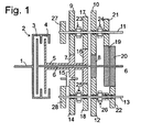
- stepped transmission has a drive shaft 1 which is connected to an engine, not shown, of a motor vehicle and a double clutch 2 with independently operable part clutches 3, 4 input shafts 5, 6 drives.
- the input shaft 5, which can be driven via the partial clutch 4 is hollow, and the input shaft 6, which is connected to the partial clutch 3, runs coaxially in its interior.
- Both input shafts 5, 6 carry fixed wheels 7, 8 of the same diameter, which form with idler gears 9, 10 of a countershaft 11 two sets of wheels with the same ratio.
- the fixed gear 8 also meshes with a loose wheel 12 of a second countershaft 13.
- the distance between the countershaft 13 on the one hand and the input shafts 5, 6 on the other hand is smaller than that between the countershaft 11 and the input shafts 5, 6, so that the diameter of the idler gear 12th smaller than that of the idler gear 10 and the gear ratio of the wheel set formed by the wheels 8, 12 is higher than that of the wheelset 8, 10.
- the sets of wheels 7, 9 and 8, 10 each represent a first gear of the transmission and the wheelset 8, 12 a second gear.
- the fixed gear 7 is located on the second countershaft 13, a loose wheel 14 opposite, which is slightly smaller than the idler gear 9. It is therefore not directly, but coupled via an intermediate 15 to the fixed gear 7 and thus represents a reverse gear with a slightly higher gear ratio than that of the first gear.
- the wheelset from the wheels 16, 17 represents a third, consisting of the wheels 16, 18 is a fifth gear of the transmission.
- the two fixed wheels 19, 20 may possibly also be merged into a single, with both idler gears 21, 22 meshing wheel.
- Jaw clutches 23 to 26 with lock synchronization which are each arranged between pairs of idler gears 9 and 17, 10 and 21, 14 and 18 and 12 and 22, serve to establish a rotationally fixed connection to the respective countershaft 11 and 13, which then a wheel 27 or 28 drives a not shown, two countershafts 11, 13 common output shaft and finally wheels of the motor vehicle.
- the dog clutches 23 - 26 are space-saving, axially overlapping in pairs, arranged on the two countershafts 11, 13.
- the idler gears 9, 10 are coupled simultaneously via the jaw clutches 23, 24 to the countershaft 11.
- the partial clutch 3 is opened, so that the input shaft 6 is load-free, and the dog clutch 24 is opened.
- the idler gear 12 is coupled to the countershaft 13 via the dog clutch 26.
- the part clutch 4 is closed and the part clutch 3 is opened.
- the idler gear 21 is coupled to the dog clutch 24; then the part clutch 3 are closed and the part clutch 4 is opened at the same time.
- the scheme of Fig. 2 does not provide that the transmission path of the torque via the wheels 8, 10 is switchable, if not the same time the path is connected via the pair of wheels 7.9.
- the possibility can be created without difficulty of switching the torque flow from the third to the first gear by using the path via the wheels 8, 10 in first gear.
Landscapes
- Engineering & Computer Science (AREA)
- General Engineering & Computer Science (AREA)
- Mechanical Engineering (AREA)
- Structure Of Transmissions (AREA)
Description
- Die vorliegende Erfindung betrifft ein Stufengetriebe mit Doppelkupplung, insbesondere für ein Kraftfahrzeug nach dem Oberbegriff des Anspruchs 1.
- Ein solches Getriebe ist aus
JP 2006 132 572 A1 US 2005/0209042 A1 bekannt. -
DE 199 11 027 A1 offenbart ein Doppelkupplungsgetriebe mit einer Antriebswelle, zwei Eingangswellen, zwei Kupplungen zum Übertragen von Drehmoment von der Antriebswelle wahlweise auf die erste oder die zweite Eingangswelle, und einer Mehrzahl von von der Antriebswelle über eine der Eingangswellen zu einer gleichen Ausgangswelle verlaufenden Radsätzen zum Übertragen des Drehmoments von Antriebswelle auf die Ausgangswelle mit einer Mehrzahl von Übersetzungsverhältnissen. Zwei sich über jeweils verschiedene Eingangswellen erstreckende Radsätze haben dasselbe Übersetzungsverhältnis, um beim Anfahren beide Kupplungen geschlossen halten zu können. So steht für einen Anfahrvorgang unter hoher Last, zum Beispiel beim Anfahren mit Anhänger an einem Hang, eine hohe Drehmomentübertragungskapazität zur Verfügung. - Aufgabe der vorliegenden Erfindung ist, ein Doppelkupplungsgetriebe der eingangs beschriebenen Art so weiterzubilden, dass bei kompakter Bauform bzw. mit einer geringen Zahl von Rädern die Realisierung einer großen Zahl verschiedener Übersetzungsverhältnisse realisierbar ist.
- Die Aufgabe wird gelöst durch ein Stufengetriebe mit den Merkmalen des Anspruchs 1. Indem zu zwei Radsätzen eines herkömmlichen Stufengetriebes, die einen ersten Gang bzw. einen zweiten Gang übertragen, ein Radsatz hinzugefügt wird, dessen Übersetzungsverhältnis näher an dem ersten als an dem zweiten Gang liegt, ist die Reibungswärme, die bei gleichzeitiger Nutzung des dem ersten Gang zugeordneten Radsatzes und des zusätzlichen Radsatzes frei wird, natürlich kleiner als bei gleichzeitiger Nutzung der Radsätze des ersten und des zweiten Gangs. Da die von den Teilkupplungen aufzunehmende Wärmemenge gering ist, können diese klein und leicht ausgeführt werden. Die Doppelkupplungen können somit preiswert gefertigt werden, und ihr verringertes Trägheitsmoment ermöglicht außerdem Kraftstoffeinsparungen im Betrieb.
- Wenn, wie gemäß der Erfindung vorgesehen, die Zahl der Vorgelegewellen zwei ist, könnten dem ersten und dem zweiten Radsatz jeweils von verschiedenen Vorgelegewellen oder von derselben Vorgelegewelle getragene Räder angehören. Wenn sie verschiedenen Vorgelegewellen angehören, und beide Vorgelegewellen einen gleichen Abstand von den koaxialen Antriebswellen haben, dann könnte ein von einer Antriebswelle getragenes Rad, wenn es mit Rädern beider Vorgelegewellen kämmt, nur zu beiden Vorgelegewellen dasselbe Übersetzungsverhältnis realisieren. Es würde daher für den Bau eines Getriebes mit einer gegebenen Zahl von Übersetzungsverhältnissen eine relativ hohe Zahl von Rädern benötigt. Die Erfindung sieht deshalb für die erste Vorgelegewelle einen größeren Abstand von den koaxialen Antriebswellen vor als für die zweite Vorgelegewelle. Indem ferner dem ersten und dem zweiten Radsatz jeweils von der ersten Vorgelegewelle getragene Räder angehören, ist beim dritten Radsatz ein höheres Übersetzungsverhältnis als das des ersten und des zweiten Radsatzes realisierbar, indem diesem dritten Radsatz das von einer Eingangswelle getragene Rad des zweitens Radsatzes und ein Rad an der zweiten Vorgelegewelle angehört.
- Dieser zweite Radsatz muss nicht als ein eigenständiger Gang auswählbar sein; hierfür wird er aufgrund seiner kleinen Stufung zum ersten Gang in der Regel nicht benötigt. Seine Nutzung kann jedoch vorteilhaft sein, um ein unterbrechungsfreies Schalten in den dritten Gang zu ermöglichen, wie später noch genauer erläutert wird.
- Wenn erster und zweiter Radsatz das gleiche Übersetzungsverhältnis haben, ist durch die Nutzung dieser beiden Radsätze beim Anfahren ein Gleichlauf zwischen den zwei Eingangswellen realisierbar, und beide Teilkupplungen der Doppelkupplung können bis zum Erreichen ihrer maximalen Drehmomentübertragungskapazität geschlossen werden. Aufgrund des Gleichlaufs der zwei Eingangswellen wird bei einem Anfahren mit dem erfindungsgemäßen Stufengetriebe nicht mehr Reibungswärme in der Kupplung freigesetzt als beim Anfahren unter Verwendung einer einzigen Teilkupplung.
- Wenn auch der erste Radsatz ein von einer Eingangswelle getragenes Rad mit einem vierten Radsatz gemeinsam hat, so bildet dieser vierte Radsatz zweckmäßigerweise einen Rückwärtsgang.
- Um höhere Gänge darzustellen, trägt zweckmäßigerweise wenigstens eine der Eingangswellen ein Rad, das größer als die von den Eingangswellen getragenen Räder des ersten und des zweiten Radsatzes ist, und das zwei Radsätzen angehört.
- Weitere Merkmale und Vorteile der Erfindung ergeben sich aus der nachfolgenden Beschreibung eines
- Ausführungsbeispiels unter Bezugnahme auf die beigefügten Figuren. Es zeigen:
- Fig. 1
- eine schematische Darstellung eines erfindungsgemäßen Stufengetriebes; und
- Fig. 2
- eine tabellarische Darstellung des Drehmomentflusses im Getriebe der
Fig. 1 in verschiedenen Schaltzuständen. - Das in
Fig. 1 gezeigte Stufengetriebe hat eine Antriebswelle 1, die mit einem nicht dargestellten Motor eines Kraftfahrzeugs verbunden ist und über eine Doppelkupplung 2 mit unabhängig voneinander betätigbaren Teilkupplungen 3, 4 Eingangswellen 5, 6 eintreibt. Die über die Teilkupplung 4 antreibbare Eingangswelle 5 ist hohl, und in ihrem Inneren verläuft koaxial die mit der Teilkupplung 3 verbundene Eingangswelle 6. - Beide Eingangswellen 5, 6 tragen Festräder 7, 8 von gleichem Durchmesser, die mit Losrädern 9, 10 einer Vorgelegewelle 11 zwei Radsätze mit gleichem Übersetzungsverhältnis bilden. Das Festrad 8 kämmt außerdem mit einem Losrad 12 einer zweiten Vorgelegewelle 13. Der Abstand zwischen der Vorgelegewelle 13 einerseits und den Eingangswellen 5, 6 andererseits ist kleiner als der zwischen der Vorgelegewelle 11 und den Eingangswellen 5, 6, so dass der Durchmesser des Losrades 12 kleiner als der des Losrades 10 und des Übersetzungsverhältnis des von den Rädern 8, 12 gebildeten Radsatzes höher als das des Radsatzes 8, 10 ist. Genauer gesagt stellen die Radsätze 7, 9 und 8, 10 jeweils einen ersten Gang des Getriebes dar und der Radsatz 8, 12 einen zweiten Gang.
- Dem Festrad 7 liegt an der zweiten Vorgelegewelle 13 ein Losrad 14 gegenüber, das geringfügig kleiner als das Losrad 9 ist. Es ist daher nicht direkt, sondern über ein Zwischenrad 15 an das Festrad 7 gekoppelt und stellt so einen Rückwärtsgang mit einem geringfügig höheren Übersetzungsverhältnis als dem des ersten Ganges dar.
- Ein zweites Festrad 16 der Eingangswelle 5, das größer als die Festräder 7, 8 ist, kämmt mit einem Losrad 17 der Vorgelegewelle 11 und einem Losrad 18 der Vorgelegewelle 13. Der Radsatz aus den Rädern 16, 17 stellt einen dritten, der aus den Rädern 16, 18 einen fünften Gang des Getriebes dar.
- Zwei Festräder 19, 20 der Eingangswelle 6, die wiederum größer sind als das Rad 16, kämmen mit Losrädern 21, 22 der Vorgelegewelle 11 bzw. 13, um einen vierten und einen sechsten Gang darzustellen. Die zwei Festräder 19, 20 können eventuell auch zu einem einzigen, mit beiden Losrädern 21, 22 kämmenden Rad verschmolzen sein.
- Klauenkupplungen 23 bis 26 mit Sperrsynchronisation, die jeweils zwischen Paaren von Losrädern 9 und 17, 10 und 21, 14 und 18 bzw. 12 und 22 angeordnet sind, dienen zum Herstellen einer drehfesten Verbindung zu der jeweiligen Vorgelegewelle 11 bzw. 13, die dann über ein Rad 27 bzw. 28 eine nicht dargestellte, beiden Vorgelegewellen 11, 13 gemeinsame Abtriebswelle und schließlich Räder des Kraftfahrzeugs antreibt. Die Klauenkupplungen 23 - 26 sind platzsparend, paarweise axial überlappend, an den zwei Vorgelegewellen 11, 13 angeordnet.
- Zum Anfahren im ersten Gang, bei geschlossenen Teilkupplungen 3, 4, sind die Losräder 9, 10 gleichzeitig über die Klauenkupplungen 23, 24 an die Vorgelegewelle 11 gekoppelt. Nach dem Anfahren wird die Teilkupplung 3 geöffnet, so dass die Eingangswelle 6 lastfrei wird, und die Klauenkupplung 24 wird geöffnet. Vor dem Umschalten in den 2. Gang wird über die Klauenkupplung 26 das Losrad 12 an die Vorgelegewelle 13 gekoppelt. Durch Schließen der Teilkupplung 3 und gleichzeitiges Öffnen der Teilkupplung 4 wird der zweite Gang eingelegt.
- Entsprechend wird zum Umschalten vom zweiten in den dritten Gang zunächst das Losrad 9 von der Vorgelegewelle 11 ab-und das Losrad 17 angekoppelt, dann wird die Teilkupplung 4 geschlossen und die Teilkupplung 3 geöffnet. Zum Umschalten in den 4. Gang wird an der Klauenkupplung 24 das Losrad 21 angekoppelt; dann werden gleichzeitig die Teilkupplung 3 geschlossen und die Teilkupplung 4 geöffnet.
- Zum Umschalten in den 5. Gang wird zunächst an der Klauenkupplung 25 das Gangrad 18 an die Vorgelegewelle 13 gekoppelt, und nach Umschalten der Teilkupplungen 3, 4 wird die Klauenkupplung 24 geöffnet. Das Umschalten in den 6. Gang erfolgt durch Ankoppeln des Losrades 22 an die Vorgelegewelle 13, gefolgt vom Umschalten der Teilkupplungen 3, 4.
- In analoger Weise kann schrittweise vom sechsten in den ersten Gang zurückgeschaltet werden, ohne jemals den Drehmomentfluss zu unterbrechen, indem jeweils der nächst niedrigere Gang zunächst vorgewählt und dann durch Umschalten der Teilkupplungen 3, 4 eingelegt wird. Die hierfür benutzten Räder und Kupplungen sowie die Richtung der Drehmomentübertragung zwischen ihnen sind in
Fig. 2 tabellarisch zusammengefasst. - Das Schema der
Fig. 2 sieht nicht vor, dass der Übertragungsweg des Drehmoments über die Räder 8, 10 schaltbar ist, wenn nicht gleichzeitig der Weg über das Räderpaar 7,9 geschaltet ist. Einer Weiterentwicklung zufolge kann jedoch problemlos, ohne irgendwelche Veränderungen am Aufbau des Getriebes, die Möglichkeit geschaffen werden, ohne Unterbrechung des Drehmomentflusses vom dritten in den ersten Gang zu schalten, indem im ersten Gang der Weg über die Räder 8, 10 genutzt wird. -
- Antriebswelle
- 1
- Doppelkupplung
- 2
- Teilkupplungen
- 3, 4
- Eingangswellen
- 5, 6
- Festräder
- 7, 8
- Losräder
- 9, 10
- Vorgelegewelle
- 11
- Losrad
- 12
- Vorgelegewelle
- 13
- Losrad
- 14
- Zwischenrad
- 15
- Festrad
- 16
- Losrad
- 17, 18
- Festrad
- 19, 20
- Losrad
- 21, 22
- Klauenkupplung
- 23-26
- Rad
- 27, 28
Claims (5)
- Stufengetriebe mit einer Antriebswelle (1), zwei zueinander koaxialen Eingangswellen (5, 6), einer Doppelkupplung (2) zum Übertragen von Drehmoment von der Antriebswelle (1) wahlweise auf die erste oder die zweite Eingangswelle (5, 6), und einer Mehrzahl von Radsätzen (7, 9; 8, 10; 8, 12; 16, 17; 16, 18; ...) zum Übertragen des Drehmoments von der ersten oder der zweiten Eingangswelle (6, 5) auf wenigstens eine Vorgelegewelle (11, 13) mit einer Mehrzahl von Übersetzungsverhältnissen, wobei die Stufung zwischen einem ersten Radsatz (7, 9) zum Übertragen des Drehmoments von der ersten Eingangswelle (5), der das niedrigste Übersetzungsverhältnis aus der Mehrzahl von Übersetzungsverhältnissen aufweist, und einem zweiten Radsatz (8, 10) zum Übertragen des Drehmoments von der zweiten Eingangswelle (6), der das zweitniedrigste Übersetzungsverhältnis aus der Mehrzahl von Übersetzungsverhältnissen aufweist, kleiner ist als zwischen dem zweiten Radsatz (8, 10) und einem dritten Radsatz (8, 12), der das drittniedrigste Übersetzungsverhältnis aufweist, wobei die Zahl der Vorgelegewellen (11, 13) zwei ist und dem ersten und dem zweiten Radsatz (7, 9; 8, 10) jeweils von einer ersten (11) der Vorgelegewellen getragene Räder (9, 10) angehören, dadurch gekennzeichnet, dass die erste Vorgelegewelle (11) weiter als die zweite Vorgelegewelle (13) von den Eingangswellen (5, 6) beabstandet ist, und dass das von der zweiten Eingangswelle (6) getragene Rad (8) des zweiten Radsatzes (8, 10) mit einem von der zweiten Vorgelegewelle (13) getragenen Rad (12) den dritten Radsatz (8, 12) bildet.
- Stufengetriebe nach Anspruch 1, dadurch gekennzeichnet, dass der erste und der zweite Radsatz (8, 10; 7,9) das gleiche Übersetzungsverhältnis aufweisen.
- Stufengetriebe nach Anspruch 1 oder 2, dadurch gekennzeichnet, dass auch der erste Radsatz (7, 9) ein von der ersten Eingangswelle (5) getragenes Rad (7) mit einem vierten Radsatz (7, 15, 14) gemeinsam hat, und dass der vierte Radsatz (7, 15, 14) einen Rückwärtsgang bildet.
- Stufengetriebe nach Anspruch 1, 2 oder 3, dadurch gekennzeichnet, dass wenigstens eine der Eingangswellen (5) ein Rad (16) trägt, das größer als die von den Eingangswellen (5, 6) getragenen Räder (8, 7) des ersten und des zweiten Radsatzes (7, 9; 8, 10) ist, und dass das größere Rad (16) zwei Radsätzen (16, 17; 16, 18) angehört.
- Stufengetriebe nach einem der vorhergehenden Ansprüche, dadurch gekennzeichnet, dass eine der Eingangswellen (6) sich durch einen Hohlraum der anderen Eingangswelle (5) hindurch erstreckt.
Applications Claiming Priority (1)
| Application Number | Priority Date | Filing Date | Title |
|---|---|---|---|
| DE102007034553A DE102007034553A1 (de) | 2007-07-21 | 2007-07-21 | Stufengetriebe mit Doppelkupplung |
Publications (3)
| Publication Number | Publication Date |
|---|---|
| EP2019229A2 EP2019229A2 (de) | 2009-01-28 |
| EP2019229A3 EP2019229A3 (de) | 2010-04-07 |
| EP2019229B1 true EP2019229B1 (de) | 2011-10-12 |
Family
ID=39832240
Family Applications (1)
| Application Number | Title | Priority Date | Filing Date |
|---|---|---|---|
| EP08008968A Not-in-force EP2019229B1 (de) | 2007-07-21 | 2008-05-15 | Stufengetriebe mit Doppelkupplung |
Country Status (3)
| Country | Link |
|---|---|
| EP (1) | EP2019229B1 (de) |
| AT (1) | ATE528538T1 (de) |
| DE (1) | DE102007034553A1 (de) |
Families Citing this family (4)
| Publication number | Priority date | Publication date | Assignee | Title |
|---|---|---|---|---|
| DE102009002356B4 (de) * | 2009-04-14 | 2017-07-06 | Zf Friedrichshafen Ag | Doppelkupplungsgetriebe |
| US8302500B2 (en) * | 2009-04-22 | 2012-11-06 | GM Global Technology Operations LLC | Dual clutch transmission |
| JP5436354B2 (ja) * | 2010-06-24 | 2014-03-05 | 本田技研工業株式会社 | ツインクラッチ式変速装置 |
| DE102011113288B4 (de) | 2011-09-12 | 2013-05-08 | Getrag Getriebe- Und Zahnradfabrik Hermann Hagenmeyer Gmbh & Cie Kg | Kfz-Antriebsstrang und Verfahren zum Betreiben eines Antriebsstranges |
Family Cites Families (10)
| Publication number | Priority date | Publication date | Assignee | Title |
|---|---|---|---|---|
| DE3546454C2 (de) * | 1985-08-22 | 1994-11-03 | Porsche Ag | Gangschaltgetriebe für ein Kraftfahrzeug mit Doppelkupplung |
| DE19923185A1 (de) * | 1999-05-20 | 2000-12-07 | Daimler Chrysler Ag | Zahnräderwechselgetriebe mit zwei im Kraftfluß parallel zueinander angeordneten Teilgetrieben |
| DE19911027C2 (de) * | 1999-03-12 | 2000-12-28 | Bosch Gmbh Robert | Mehrgängiges Schaltgetriebe für ein Kraftfahrzeug mit Doppelkupplung |
| DE10060699A1 (de) * | 1999-12-16 | 2001-06-21 | Luk Lamellen & Kupplungsbau | Getriebe und Verfahren zum Betreiben eines Getriebes |
| WO2001088409A2 (de) * | 2000-05-17 | 2001-11-22 | Luk Lamellen Und Kupplungsbau Beteiligungs Kg | Getriebe mit kupplung sowie verfahren zum betreiben einer kupplung |
| DE10305241A1 (de) | 2003-02-08 | 2004-09-23 | Zf Friedrichshafen Ag | Sechs- oder siebengängiges Doppelkupplungsgetriebe |
| US7083540B2 (en) * | 2004-03-18 | 2006-08-01 | Ford Global Technologies, Llc | Dual clutch transmission having low gear mesh loss |
| JP2006002917A (ja) * | 2004-06-21 | 2006-01-05 | Aisin Ai Co Ltd | 複数のクラッチを持つ変速装置 |
| JP2006132572A (ja) * | 2004-11-02 | 2006-05-25 | Exedy Corp | 変速装置 |
| GB0516726D0 (en) * | 2005-08-15 | 2005-09-21 | Ricardo Uk Ltd | Twin layshaft transmission |
-
2007
- 2007-07-21 DE DE102007034553A patent/DE102007034553A1/de not_active Withdrawn
-
2008
- 2008-05-15 AT AT08008968T patent/ATE528538T1/de active
- 2008-05-15 EP EP08008968A patent/EP2019229B1/de not_active Not-in-force
Also Published As
| Publication number | Publication date |
|---|---|
| EP2019229A3 (de) | 2010-04-07 |
| EP2019229A2 (de) | 2009-01-28 |
| ATE528538T1 (de) | 2011-10-15 |
| DE102007034553A1 (de) | 2009-01-22 |
Similar Documents
| Publication | Publication Date | Title |
|---|---|---|
| EP2791548B1 (de) | Doppelkupplungsgetriebe | |
| DE102011076386B4 (de) | Doppelkupplungsgetriebe | |
| EP2162635B1 (de) | Zahnräderwechselgetriebe | |
| DE102010003924A1 (de) | Doppelkupplungs-Gruppengetriebe und Verfahren zur Betätigung eines Doppelkupplungs-Gruppengetriebes | |
| EP1846669A1 (de) | Doppelkupplungsgetriebe | |
| DE102011076382A1 (de) | Doppelkupplungsgetriebe | |
| DE102011056517A1 (de) | Getriebe für ein Kraftfahrzeug und Verfahren zum Steuern eines solchen Getriebes | |
| EP3259493B1 (de) | Doppelkupplungsgetriebe für ein kraftfahrzeug | |
| WO2008092566A1 (de) | Schaltgetriebe mit doppelter kupplung | |
| DE102011000151A1 (de) | Getriebe für ein Kraftfahrzeug und Verfahren zum Steuern eines solchen Getriebes | |
| DE102007004291A1 (de) | Schaltgetriebe | |
| DE102007049263A1 (de) | Doppelkupplungsgetriebe | |
| WO2015149823A1 (de) | Geschwindigkeits-wechselgetriebe für ein kraftfahrzeug | |
| DE102009002356A1 (de) | Doppelkupplungsgetriebe | |
| WO2011085924A1 (de) | Verfahren zum betreiben eines fahrzeugantriebsstranges mit einer brennkraftmaschine | |
| DE102011089167A1 (de) | Doppelkupplungsgetriebe in Vorgelegebauweise | |
| EP2019229A2 (de) | Stufengetriebe mit Doppelkupplung | |
| EP3472490B1 (de) | Doppelkupplungsgetriebe mit brückenkupplung | |
| DE102015204600B4 (de) | Getriebe für ein Kraftfahrzeug und Verfahren zum Betreiben eines solchen | |
| DE102010010401A1 (de) | Doppelkupplungsgetriebe mit Planetengetrieben für ein Fahrzeug | |
| DE102011089155A1 (de) | Doppelkupplungsgetriebe |
Legal Events
| Date | Code | Title | Description |
|---|---|---|---|
| PUAI | Public reference made under article 153(3) epc to a published international application that has entered the european phase |
Free format text: ORIGINAL CODE: 0009012 |
|
| AK | Designated contracting states |
Kind code of ref document: A2 Designated state(s): AT BE BG CH CY CZ DE DK EE ES FI FR GB GR HR HU IE IS IT LI LT LU LV MC MT NL NO PL PT RO SE SI SK TR |
|
| AX | Request for extension of the european patent |
Extension state: AL BA MK RS |
|
| PUAL | Search report despatched |
Free format text: ORIGINAL CODE: 0009013 |
|
| AK | Designated contracting states |
Kind code of ref document: A3 Designated state(s): AT BE BG CH CY CZ DE DK EE ES FI FR GB GR HR HU IE IS IT LI LT LU LV MC MT NL NO PL PT RO SE SI SK TR |
|
| AX | Request for extension of the european patent |
Extension state: AL BA MK RS |
|
| 17P | Request for examination filed |
Effective date: 20101007 |
|
| AKX | Designation fees paid |
Designated state(s): AT BE BG CH CY CZ DE DK EE ES FI FR GB GR HR HU IE IS IT LI LT LU LV MC MT NL NO PL PT RO SE SI SK TR |
|
| 17Q | First examination report despatched |
Effective date: 20101027 |
|
| RIC1 | Information provided on ipc code assigned before grant |
Ipc: F16H 3/093 20060101ALI20110304BHEP Ipc: F16H 3/00 20060101AFI20110304BHEP |
|
| GRAP | Despatch of communication of intention to grant a patent |
Free format text: ORIGINAL CODE: EPIDOSNIGR1 |
|
| RAP1 | Party data changed (applicant data changed or rights of an application transferred) |
Owner name: GM GLOBAL TECHNOLOGY OPERATIONS LLC |
|
| GRAS | Grant fee paid |
Free format text: ORIGINAL CODE: EPIDOSNIGR3 |
|
| GRAA | (expected) grant |
Free format text: ORIGINAL CODE: 0009210 |
|
| AK | Designated contracting states |
Kind code of ref document: B1 Designated state(s): AT BE BG CH CY CZ DE DK EE ES FI FR GB GR HR HU IE IS IT LI LT LU LV MC MT NL NO PL PT RO SE SI SK TR |
|
| REG | Reference to a national code |
Ref country code: GB Ref legal event code: FG4D Free format text: NOT ENGLISH |
|
| REG | Reference to a national code |
Ref country code: CH Ref legal event code: EP |
|
| REG | Reference to a national code |
Ref country code: IE Ref legal event code: FG4D |
|
| REG | Reference to a national code |
Ref country code: DE Ref legal event code: R096 Ref document number: 502008005114 Country of ref document: DE Effective date: 20111208 |
|
| REG | Reference to a national code |
Ref country code: NL Ref legal event code: VDEP Effective date: 20111012 |
|
| LTIE | Lt: invalidation of european patent or patent extension |
Effective date: 20111012 |
|
| PG25 | Lapsed in a contracting state [announced via postgrant information from national office to epo] |
Ref country code: IS Free format text: LAPSE BECAUSE OF FAILURE TO SUBMIT A TRANSLATION OF THE DESCRIPTION OR TO PAY THE FEE WITHIN THE PRESCRIBED TIME-LIMIT Effective date: 20120212 Ref country code: NO Free format text: LAPSE BECAUSE OF FAILURE TO SUBMIT A TRANSLATION OF THE DESCRIPTION OR TO PAY THE FEE WITHIN THE PRESCRIBED TIME-LIMIT Effective date: 20120112 Ref country code: LT Free format text: LAPSE BECAUSE OF FAILURE TO SUBMIT A TRANSLATION OF THE DESCRIPTION OR TO PAY THE FEE WITHIN THE PRESCRIBED TIME-LIMIT Effective date: 20111012 |
|
| REG | Reference to a national code |
Ref country code: IE Ref legal event code: FD4D |
|
| PG25 | Lapsed in a contracting state [announced via postgrant information from national office to epo] |
Ref country code: SE Free format text: LAPSE BECAUSE OF FAILURE TO SUBMIT A TRANSLATION OF THE DESCRIPTION OR TO PAY THE FEE WITHIN THE PRESCRIBED TIME-LIMIT Effective date: 20111012 Ref country code: NL Free format text: LAPSE BECAUSE OF FAILURE TO SUBMIT A TRANSLATION OF THE DESCRIPTION OR TO PAY THE FEE WITHIN THE PRESCRIBED TIME-LIMIT Effective date: 20111012 Ref country code: PT Free format text: LAPSE BECAUSE OF FAILURE TO SUBMIT A TRANSLATION OF THE DESCRIPTION OR TO PAY THE FEE WITHIN THE PRESCRIBED TIME-LIMIT Effective date: 20120213 Ref country code: LV Free format text: LAPSE BECAUSE OF FAILURE TO SUBMIT A TRANSLATION OF THE DESCRIPTION OR TO PAY THE FEE WITHIN THE PRESCRIBED TIME-LIMIT Effective date: 20111012 Ref country code: HR Free format text: LAPSE BECAUSE OF FAILURE TO SUBMIT A TRANSLATION OF THE DESCRIPTION OR TO PAY THE FEE WITHIN THE PRESCRIBED TIME-LIMIT Effective date: 20111012 Ref country code: SI Free format text: LAPSE BECAUSE OF FAILURE TO SUBMIT A TRANSLATION OF THE DESCRIPTION OR TO PAY THE FEE WITHIN THE PRESCRIBED TIME-LIMIT Effective date: 20111012 Ref country code: GR Free format text: LAPSE BECAUSE OF FAILURE TO SUBMIT A TRANSLATION OF THE DESCRIPTION OR TO PAY THE FEE WITHIN THE PRESCRIBED TIME-LIMIT Effective date: 20120113 |
|
| PG25 | Lapsed in a contracting state [announced via postgrant information from national office to epo] |
Ref country code: CY Free format text: LAPSE BECAUSE OF FAILURE TO SUBMIT A TRANSLATION OF THE DESCRIPTION OR TO PAY THE FEE WITHIN THE PRESCRIBED TIME-LIMIT Effective date: 20111012 |
|
| PG25 | Lapsed in a contracting state [announced via postgrant information from national office to epo] |
Ref country code: EE Free format text: LAPSE BECAUSE OF FAILURE TO SUBMIT A TRANSLATION OF THE DESCRIPTION OR TO PAY THE FEE WITHIN THE PRESCRIBED TIME-LIMIT Effective date: 20111012 Ref country code: BG Free format text: LAPSE BECAUSE OF FAILURE TO SUBMIT A TRANSLATION OF THE DESCRIPTION OR TO PAY THE FEE WITHIN THE PRESCRIBED TIME-LIMIT Effective date: 20120112 Ref country code: DK Free format text: LAPSE BECAUSE OF FAILURE TO SUBMIT A TRANSLATION OF THE DESCRIPTION OR TO PAY THE FEE WITHIN THE PRESCRIBED TIME-LIMIT Effective date: 20111012 Ref country code: SK Free format text: LAPSE BECAUSE OF FAILURE TO SUBMIT A TRANSLATION OF THE DESCRIPTION OR TO PAY THE FEE WITHIN THE PRESCRIBED TIME-LIMIT Effective date: 20111012 Ref country code: IE Free format text: LAPSE BECAUSE OF FAILURE TO SUBMIT A TRANSLATION OF THE DESCRIPTION OR TO PAY THE FEE WITHIN THE PRESCRIBED TIME-LIMIT Effective date: 20111012 Ref country code: CZ Free format text: LAPSE BECAUSE OF FAILURE TO SUBMIT A TRANSLATION OF THE DESCRIPTION OR TO PAY THE FEE WITHIN THE PRESCRIBED TIME-LIMIT Effective date: 20111012 |
|
| PLBE | No opposition filed within time limit |
Free format text: ORIGINAL CODE: 0009261 |
|
| STAA | Information on the status of an ep patent application or granted ep patent |
Free format text: STATUS: NO OPPOSITION FILED WITHIN TIME LIMIT |
|
| PG25 | Lapsed in a contracting state [announced via postgrant information from national office to epo] |
Ref country code: RO Free format text: LAPSE BECAUSE OF FAILURE TO SUBMIT A TRANSLATION OF THE DESCRIPTION OR TO PAY THE FEE WITHIN THE PRESCRIBED TIME-LIMIT Effective date: 20111012 Ref country code: PL Free format text: LAPSE BECAUSE OF FAILURE TO SUBMIT A TRANSLATION OF THE DESCRIPTION OR TO PAY THE FEE WITHIN THE PRESCRIBED TIME-LIMIT Effective date: 20111012 Ref country code: IT Free format text: LAPSE BECAUSE OF FAILURE TO SUBMIT A TRANSLATION OF THE DESCRIPTION OR TO PAY THE FEE WITHIN THE PRESCRIBED TIME-LIMIT Effective date: 20111012 |
|
| 26N | No opposition filed |
Effective date: 20120713 |
|
| REG | Reference to a national code |
Ref country code: DE Ref legal event code: R097 Ref document number: 502008005114 Country of ref document: DE Effective date: 20120713 |
|
| BERE | Be: lapsed |
Owner name: GM GLOBAL TECHNOLOGY OPERATIONS LLC Effective date: 20120531 |
|
| PG25 | Lapsed in a contracting state [announced via postgrant information from national office to epo] |
Ref country code: MC Free format text: LAPSE BECAUSE OF NON-PAYMENT OF DUE FEES Effective date: 20120531 |
|
| REG | Reference to a national code |
Ref country code: CH Ref legal event code: PL |
|
| PG25 | Lapsed in a contracting state [announced via postgrant information from national office to epo] |
Ref country code: CH Free format text: LAPSE BECAUSE OF NON-PAYMENT OF DUE FEES Effective date: 20120531 Ref country code: LI Free format text: LAPSE BECAUSE OF NON-PAYMENT OF DUE FEES Effective date: 20120531 |
|
| PG25 | Lapsed in a contracting state [announced via postgrant information from national office to epo] |
Ref country code: BE Free format text: LAPSE BECAUSE OF NON-PAYMENT OF DUE FEES Effective date: 20120531 |
|
| PG25 | Lapsed in a contracting state [announced via postgrant information from national office to epo] |
Ref country code: ES Free format text: LAPSE BECAUSE OF FAILURE TO SUBMIT A TRANSLATION OF THE DESCRIPTION OR TO PAY THE FEE WITHIN THE PRESCRIBED TIME-LIMIT Effective date: 20120123 |
|
| PG25 | Lapsed in a contracting state [announced via postgrant information from national office to epo] |
Ref country code: FI Free format text: LAPSE BECAUSE OF FAILURE TO SUBMIT A TRANSLATION OF THE DESCRIPTION OR TO PAY THE FEE WITHIN THE PRESCRIBED TIME-LIMIT Effective date: 20111012 |
|
| PG25 | Lapsed in a contracting state [announced via postgrant information from national office to epo] |
Ref country code: MT Free format text: LAPSE BECAUSE OF FAILURE TO SUBMIT A TRANSLATION OF THE DESCRIPTION OR TO PAY THE FEE WITHIN THE PRESCRIBED TIME-LIMIT Effective date: 20111012 |
|
| PG25 | Lapsed in a contracting state [announced via postgrant information from national office to epo] |
Ref country code: TR Free format text: LAPSE BECAUSE OF FAILURE TO SUBMIT A TRANSLATION OF THE DESCRIPTION OR TO PAY THE FEE WITHIN THE PRESCRIBED TIME-LIMIT Effective date: 20111012 |
|
| PG25 | Lapsed in a contracting state [announced via postgrant information from national office to epo] |
Ref country code: LU Free format text: LAPSE BECAUSE OF NON-PAYMENT OF DUE FEES Effective date: 20120515 |
|
| REG | Reference to a national code |
Ref country code: AT Ref legal event code: MM01 Ref document number: 528538 Country of ref document: AT Kind code of ref document: T Effective date: 20130515 |
|
| PG25 | Lapsed in a contracting state [announced via postgrant information from national office to epo] |
Ref country code: HU Free format text: LAPSE BECAUSE OF FAILURE TO SUBMIT A TRANSLATION OF THE DESCRIPTION OR TO PAY THE FEE WITHIN THE PRESCRIBED TIME-LIMIT Effective date: 20080515 |
|
| PG25 | Lapsed in a contracting state [announced via postgrant information from national office to epo] |
Ref country code: AT Free format text: LAPSE BECAUSE OF NON-PAYMENT OF DUE FEES Effective date: 20130515 |
|
| REG | Reference to a national code |
Ref country code: FR Ref legal event code: PLFP Year of fee payment: 8 |
|
| PGFP | Annual fee paid to national office [announced via postgrant information from national office to epo] |
Ref country code: GB Payment date: 20150513 Year of fee payment: 8 Ref country code: DE Payment date: 20150512 Year of fee payment: 8 |
|
| PGFP | Annual fee paid to national office [announced via postgrant information from national office to epo] |
Ref country code: FR Payment date: 20150508 Year of fee payment: 8 |
|
| REG | Reference to a national code |
Ref country code: DE Ref legal event code: R119 Ref document number: 502008005114 Country of ref document: DE |
|
| GBPC | Gb: european patent ceased through non-payment of renewal fee |
Effective date: 20160515 |
|
| REG | Reference to a national code |
Ref country code: FR Ref legal event code: ST Effective date: 20170131 |
|
| PG25 | Lapsed in a contracting state [announced via postgrant information from national office to epo] |
Ref country code: DE Free format text: LAPSE BECAUSE OF NON-PAYMENT OF DUE FEES Effective date: 20161201 Ref country code: FR Free format text: LAPSE BECAUSE OF NON-PAYMENT OF DUE FEES Effective date: 20160531 |
|
| PG25 | Lapsed in a contracting state [announced via postgrant information from national office to epo] |
Ref country code: GB Free format text: LAPSE BECAUSE OF NON-PAYMENT OF DUE FEES Effective date: 20160515 |