EP2019239A1 - Stöpsel für ein Flussregelventil - Google Patents
Stöpsel für ein Flussregelventil Download PDFInfo
- Publication number
- EP2019239A1 EP2019239A1 EP08252252A EP08252252A EP2019239A1 EP 2019239 A1 EP2019239 A1 EP 2019239A1 EP 08252252 A EP08252252 A EP 08252252A EP 08252252 A EP08252252 A EP 08252252A EP 2019239 A1 EP2019239 A1 EP 2019239A1
- Authority
- EP
- European Patent Office
- Prior art keywords
- plug
- valve
- slots
- fluid control
- main portion
- Prior art date
- Legal status (The legal status is an assumption and is not a legal conclusion. Google has not performed a legal analysis and makes no representation as to the accuracy of the status listed.)
- Withdrawn
Links
- 239000012530 fluid Substances 0.000 title claims abstract description 8
- 239000000463 material Substances 0.000 description 1
- 238000000034 method Methods 0.000 description 1
Images

Classifications
-
- F—MECHANICAL ENGINEERING; LIGHTING; HEATING; WEAPONS; BLASTING
- F16—ENGINEERING ELEMENTS AND UNITS; GENERAL MEASURES FOR PRODUCING AND MAINTAINING EFFECTIVE FUNCTIONING OF MACHINES OR INSTALLATIONS; THERMAL INSULATION IN GENERAL
- F16K—VALVES; TAPS; COCKS; ACTUATING-FLOATS; DEVICES FOR VENTING OR AERATING
- F16K1/00—Lift valves or globe valves, i.e. cut-off apparatus with closure members having at least a component of their opening and closing motion perpendicular to the closing faces
- F16K1/32—Details
- F16K1/54—Arrangements for modifying the way in which the rate of flow varies during the actuation of the valve
-
- F—MECHANICAL ENGINEERING; LIGHTING; HEATING; WEAPONS; BLASTING
- F16—ENGINEERING ELEMENTS AND UNITS; GENERAL MEASURES FOR PRODUCING AND MAINTAINING EFFECTIVE FUNCTIONING OF MACHINES OR INSTALLATIONS; THERMAL INSULATION IN GENERAL
- F16K—VALVES; TAPS; COCKS; ACTUATING-FLOATS; DEVICES FOR VENTING OR AERATING
- F16K1/00—Lift valves or globe valves, i.e. cut-off apparatus with closure members having at least a component of their opening and closing motion perpendicular to the closing faces
- F16K1/32—Details
- F16K1/34—Cutting-off parts, e.g. valve members, seats
- F16K1/36—Valve members
Definitions
- the present invention relates to a plug and valve seat combination for a fluid control valve.
- Previously proposed plugs for fluid control valves comprise a stem portion of constant cross-section and a curved hemispherical or oblate hemispherical end portion. The shape of the end portion determines the control characteristics of the valve.
- Valves with equal percentage characteristics, where the percentage flow relates directly to the percentage that the valve is opened by, are highly desirable for ease of use, especially in the field of heat exchangers to match the characteristics of the heat exchanger.
- the present invention is directed to a plug for a fluid control valve comprising a main portion of substantially constant cross-section, means for attachment to a valve stem, in which the plug further comprises at least one slot formed in the outside surface of the main portion.
- the slot or slots formed in the surface of the main section defines the fluid control characteristics of the valve by interacting with the parallel hole in the valve seat.
- the size, shape and number of slots can be varied according to the desired characteristics of the valve.
- Such slots can easily be cut, machined or moulded into the plug using a cutter or rotary drill. It will be appreciated that a good precision can be obtained by such methods.
- the intended bottom end of the plug has a chamfered portion.
- This chamfered region can also have the slots extending through it for further control of the flow characteristics.
- the chamfered portion enables the plug to releasably engage with the parallel bore of the valve seat.
- the plug comprises three such slots in its surface. These are advantageously equally spaced round the outside of the plug, with for instance smaller valves.
- the plug comprises a main portion of approximately 4mm in length.
- Previously proposed plugs require larger strokes.
- a valve comprising a shorter stroke can be proportionately smaller, allowing the valve to be used in a wider range of applications. Furthermore less material is required for the plug.
- Figure 1 shows a plug 10 of substantially circular cross-section comprising a main portion 14, a hexagonal slot 16 for securing the plug 10 onto a valve stem 24, a chamfered portion 18 and three slots 20 (two visible).
- the hexagonal slot is used to rotate the plug 10 onto the valve stem 24 using an internal screw thread (not shown) at the other end of the plug 10.
- FIG 2 shows a balancing valve 21 equipped with the plug 10 shown in Figure 1 comprising a valve body 22, a valve stem 24, a rubber seal 26 and a valve seat 28 in which the valve plug 10 is inserted into the valve seat 28.
- the plug is attached by means of the stem 24 to the rubber seal 26 and thence to the valve body 22.
- the stem 24 moves the plug 10 to and fro through the valve seat or orifice 28.
- the rubber seal 26 rests against the valve seat 28.
- On opening the plug 10 is moved through the valve seat 28.
- the slots 20 are uncovered and fluid flow will commence. As more of the slots 20 are uncovered the flow rate will increase, until the chamfered portion 18 is reached when the flow will increase substantially.
- the valve 21 will be fully open. It will be appreciated that this arrangement allows for a substantial degree of control.
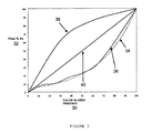
- Figure 3 shows a graph of the valve opened percentage 30 against the flow percentage 32, wherein the ideal equal percentage characteristics 34 are compared with the characteristics of a valve including the plug of the present invention 36, the heat exchanger characteristics 38 and the resultant thermal capacity 40 of the valve.
- the flow through the preferred valve arrangement is controlled by adjusting the position of the valve stem 24 which inserts and removes the plug 10 into or from the valve seat 28.
- the slots 20 in the valve plug 10 are variable in shape and size by design and therefore the flow characteristics through the valve are configurable.
Landscapes
- Engineering & Computer Science (AREA)
- General Engineering & Computer Science (AREA)
- Mechanical Engineering (AREA)
- Lift Valve (AREA)
Applications Claiming Priority (1)
| Application Number | Priority Date | Filing Date | Title |
|---|---|---|---|
| GB0712786A GB0712786D0 (en) | 2007-07-02 | 2007-07-02 | A plug for a fluid control valve |
Publications (1)
| Publication Number | Publication Date |
|---|---|
| EP2019239A1 true EP2019239A1 (de) | 2009-01-28 |
Family
ID=38421060
Family Applications (1)
| Application Number | Title | Priority Date | Filing Date |
|---|---|---|---|
| EP08252252A Withdrawn EP2019239A1 (de) | 2007-07-02 | 2008-07-02 | Stöpsel für ein Flussregelventil |
Country Status (2)
| Country | Link |
|---|---|
| EP (1) | EP2019239A1 (de) |
| GB (1) | GB0712786D0 (de) |
Cited By (1)
| Publication number | Priority date | Publication date | Assignee | Title |
|---|---|---|---|---|
| CN103062423A (zh) * | 2012-12-31 | 2013-04-24 | 浙江中控流体技术有限公司 | 阀芯阀座节流密封装置 |
Citations (9)
| Publication number | Priority date | Publication date | Assignee | Title |
|---|---|---|---|---|
| US2014314A (en) * | 1931-07-22 | 1935-09-10 | Phillips Petroleum Co | Adjustable orifice valve |
| DE2046574A1 (de) * | 1970-09-22 | 1972-03-23 | Danfoss As | Ventilverschlußstuck mit Stromungs korper und Verfahren zu dessen Herstellung |
| WO1998002682A1 (en) * | 1996-07-11 | 1998-01-22 | Tac Ab | A valve cone, a valve and a valve manufacturing process |
| EP0882921A2 (de) * | 1997-06-04 | 1998-12-09 | Furon Company | Kompaktes Ventil mit Rollmembranventilkörper |
| US20020134441A1 (en) * | 2001-03-23 | 2002-09-26 | Megatorr Corporation | Widely variable conductance valve |
| US20030042449A1 (en) * | 2001-09-06 | 2003-03-06 | Vat Holding Ag | Vacuum control valve |
| US20030116204A1 (en) * | 2001-12-26 | 2003-06-26 | Fsi International, Inc. | High flow high control valve and assembly |
| EP1375986A2 (de) * | 2002-06-28 | 2004-01-02 | Invensys Building Systems, Inc. | Präzision Modulationsitzventil |
| JP2006112539A (ja) * | 2004-10-15 | 2006-04-27 | Sumitomo Chemical Co Ltd | 流量制御弁 |
-
2007
- 2007-07-02 GB GB0712786A patent/GB0712786D0/en not_active Ceased
-
2008
- 2008-07-02 EP EP08252252A patent/EP2019239A1/de not_active Withdrawn
Patent Citations (9)
| Publication number | Priority date | Publication date | Assignee | Title |
|---|---|---|---|---|
| US2014314A (en) * | 1931-07-22 | 1935-09-10 | Phillips Petroleum Co | Adjustable orifice valve |
| DE2046574A1 (de) * | 1970-09-22 | 1972-03-23 | Danfoss As | Ventilverschlußstuck mit Stromungs korper und Verfahren zu dessen Herstellung |
| WO1998002682A1 (en) * | 1996-07-11 | 1998-01-22 | Tac Ab | A valve cone, a valve and a valve manufacturing process |
| EP0882921A2 (de) * | 1997-06-04 | 1998-12-09 | Furon Company | Kompaktes Ventil mit Rollmembranventilkörper |
| US20020134441A1 (en) * | 2001-03-23 | 2002-09-26 | Megatorr Corporation | Widely variable conductance valve |
| US20030042449A1 (en) * | 2001-09-06 | 2003-03-06 | Vat Holding Ag | Vacuum control valve |
| US20030116204A1 (en) * | 2001-12-26 | 2003-06-26 | Fsi International, Inc. | High flow high control valve and assembly |
| EP1375986A2 (de) * | 2002-06-28 | 2004-01-02 | Invensys Building Systems, Inc. | Präzision Modulationsitzventil |
| JP2006112539A (ja) * | 2004-10-15 | 2006-04-27 | Sumitomo Chemical Co Ltd | 流量制御弁 |
Cited By (1)
| Publication number | Priority date | Publication date | Assignee | Title |
|---|---|---|---|---|
| CN103062423A (zh) * | 2012-12-31 | 2013-04-24 | 浙江中控流体技术有限公司 | 阀芯阀座节流密封装置 |
Also Published As
| Publication number | Publication date |
|---|---|
| GB0712786D0 (en) | 2007-08-08 |
Similar Documents
| Publication | Publication Date | Title |
|---|---|---|
| EP3171058B1 (de) | Stromregelventil | |
| EP3249269B1 (de) | Strömungsregelventil | |
| EP4299959B1 (de) | Fluidströmungsteuerungsvorrichtungen und -systeme sowie verfahren zum strömen von fluiden dadurch | |
| US4466461A (en) | Valve | |
| WO2008144044A3 (en) | Electronically controlled valve and systems containing same | |
| EP2977657B1 (de) | Wasserhahnstruktur für konstante wassertemperatur | |
| EP2944876A1 (de) | Regelventil für ein gaskochgerät | |
| AU2015202079B2 (en) | Flow restrictor having mulitiple flow modifying regions | |
| EP1790888A8 (de) | Ventilkörper | |
| EP1727013A3 (de) | Durchflussregler mit Überdruckentlastung | |
| EP2019239A1 (de) | Stöpsel für ein Flussregelventil | |
| AU2003204640B2 (en) | Precision modulating globe valve | |
| US4684334A (en) | Inlet valve assembly for paint sprayer | |
| CA2590017A1 (en) | Fluid control valve device | |
| RU2012103336A (ru) | Модулирующий клапанный узел, содержащий устройство, устраняющее мертвый ход | |
| CN104048084B (zh) | 压力调节阀 | |
| EP3928013B1 (de) | Strömungsgesteuertes kolbenventil | |
| CA2619400C (en) | Packing nut for control valve | |
| CN216519609U (zh) | 一种用于抗颗粒可变减压级数调节阀的内件结构 | |
| EP2990704B1 (de) | Pneumatisches Ventil und Luftmatratze mit pneumatischem Ventil | |
| CN107208818B (zh) | 节流装置以及冷冻循环系统 | |
| CN109026886B (zh) | 一种先导式截止阀 | |
| EP3341636B1 (de) | Durchflussregelventil und verfahren zur herstellung eines durchflussregelventilgehäuses | |
| KR200356428Y1 (ko) | 다단식 냉온수 분배기 | |
| KR101443774B1 (ko) | 서모스탯 카트리지 |
Legal Events
| Date | Code | Title | Description |
|---|---|---|---|
| PUAI | Public reference made under article 153(3) epc to a published international application that has entered the european phase |
Free format text: ORIGINAL CODE: 0009012 |
|
| AK | Designated contracting states |
Kind code of ref document: A1 Designated state(s): AT BE BG CH CY CZ DE DK EE ES FI FR GB GR HR HU IE IS IT LI LT LU LV MC MT NL NO PL PT RO SE SI SK TR |
|
| AX | Request for extension of the european patent |
Extension state: AL BA MK RS |
|
| 17P | Request for examination filed |
Effective date: 20090728 |
|
| 17Q | First examination report despatched |
Effective date: 20090821 |
|
| AKX | Designation fees paid |
Designated state(s): AT BE BG CH CY CZ DE DK EE ES FI FR GB GR HR HU IE IS IT LI LT LU LV MC MT NL NO PL PT RO SE SI SK TR |
|
| STAA | Information on the status of an ep patent application or granted ep patent |
Free format text: STATUS: THE APPLICATION IS DEEMED TO BE WITHDRAWN |
|
| 18D | Application deemed to be withdrawn |
Effective date: 20140201 |