EP2019256A1 - Beleuchtungsmodul für Kraftfahrzeugscheinwerfer - Google Patents
Beleuchtungsmodul für Kraftfahrzeugscheinwerfer Download PDFInfo
- Publication number
- EP2019256A1 EP2019256A1 EP08160944A EP08160944A EP2019256A1 EP 2019256 A1 EP2019256 A1 EP 2019256A1 EP 08160944 A EP08160944 A EP 08160944A EP 08160944 A EP08160944 A EP 08160944A EP 2019256 A1 EP2019256 A1 EP 2019256A1
- Authority
- EP
- European Patent Office
- Prior art keywords
- light
- reflector
- emitting diode
- module
- plane
- Prior art date
- Legal status (The legal status is an assumption and is not a legal conclusion. Google has not performed a legal analysis and makes no representation as to the accuracy of the status listed.)
- Withdrawn
Links
Images
Classifications
-
- F—MECHANICAL ENGINEERING; LIGHTING; HEATING; WEAPONS; BLASTING
- F21—LIGHTING
- F21V—FUNCTIONAL FEATURES OR DETAILS OF LIGHTING DEVICES OR SYSTEMS THEREOF; STRUCTURAL COMBINATIONS OF LIGHTING DEVICES WITH OTHER ARTICLES, NOT OTHERWISE PROVIDED FOR
- F21V13/00—Producing particular characteristics or distribution of the light emitted by means of a combination of elements specified in two or more of main groups F21V1/00 - F21V11/00
- F21V13/02—Combinations of only two kinds of elements
- F21V13/04—Combinations of only two kinds of elements the elements being reflectors and refractors
-
- F—MECHANICAL ENGINEERING; LIGHTING; HEATING; WEAPONS; BLASTING
- F21—LIGHTING
- F21S—NON-PORTABLE LIGHTING DEVICES; SYSTEMS THEREOF; VEHICLE LIGHTING DEVICES SPECIALLY ADAPTED FOR VEHICLE EXTERIORS
- F21S41/00—Illuminating devices specially adapted for vehicle exteriors, e.g. headlamps
- F21S41/10—Illuminating devices specially adapted for vehicle exteriors, e.g. headlamps characterised by the light source
- F21S41/14—Illuminating devices specially adapted for vehicle exteriors, e.g. headlamps characterised by the light source characterised by the type of light source
- F21S41/141—Light emitting diodes [LED]
- F21S41/143—Light emitting diodes [LED] the main emission direction of the LED being parallel to the optical axis of the illuminating device
-
- F—MECHANICAL ENGINEERING; LIGHTING; HEATING; WEAPONS; BLASTING
- F21—LIGHTING
- F21S—NON-PORTABLE LIGHTING DEVICES; SYSTEMS THEREOF; VEHICLE LIGHTING DEVICES SPECIALLY ADAPTED FOR VEHICLE EXTERIORS
- F21S41/00—Illuminating devices specially adapted for vehicle exteriors, e.g. headlamps
- F21S41/10—Illuminating devices specially adapted for vehicle exteriors, e.g. headlamps characterised by the light source
- F21S41/14—Illuminating devices specially adapted for vehicle exteriors, e.g. headlamps characterised by the light source characterised by the type of light source
- F21S41/141—Light emitting diodes [LED]
- F21S41/147—Light emitting diodes [LED] the main emission direction of the LED being angled to the optical axis of the illuminating device
- F21S41/148—Light emitting diodes [LED] the main emission direction of the LED being angled to the optical axis of the illuminating device the main emission direction of the LED being perpendicular to the optical axis
-
- F—MECHANICAL ENGINEERING; LIGHTING; HEATING; WEAPONS; BLASTING
- F21—LIGHTING
- F21S—NON-PORTABLE LIGHTING DEVICES; SYSTEMS THEREOF; VEHICLE LIGHTING DEVICES SPECIALLY ADAPTED FOR VEHICLE EXTERIORS
- F21S41/00—Illuminating devices specially adapted for vehicle exteriors, e.g. headlamps
- F21S41/30—Illuminating devices specially adapted for vehicle exteriors, e.g. headlamps characterised by reflectors
- F21S41/32—Optical layout thereof
- F21S41/321—Optical layout thereof the reflector being a surface of revolution or a planar surface, e.g. truncated
-
- F—MECHANICAL ENGINEERING; LIGHTING; HEATING; WEAPONS; BLASTING
- F21—LIGHTING
- F21S—NON-PORTABLE LIGHTING DEVICES; SYSTEMS THEREOF; VEHICLE LIGHTING DEVICES SPECIALLY ADAPTED FOR VEHICLE EXTERIORS
- F21S41/00—Illuminating devices specially adapted for vehicle exteriors, e.g. headlamps
- F21S41/30—Illuminating devices specially adapted for vehicle exteriors, e.g. headlamps characterised by reflectors
- F21S41/32—Optical layout thereof
- F21S41/323—Optical layout thereof the reflector having two perpendicular cross sections having regular geometrical curves of a distinct nature
-
- F—MECHANICAL ENGINEERING; LIGHTING; HEATING; WEAPONS; BLASTING
- F21—LIGHTING
- F21S—NON-PORTABLE LIGHTING DEVICES; SYSTEMS THEREOF; VEHICLE LIGHTING DEVICES SPECIALLY ADAPTED FOR VEHICLE EXTERIORS
- F21S41/00—Illuminating devices specially adapted for vehicle exteriors, e.g. headlamps
- F21S41/30—Illuminating devices specially adapted for vehicle exteriors, e.g. headlamps characterised by reflectors
- F21S41/32—Optical layout thereof
- F21S41/36—Combinations of two or more separate reflectors
- F21S41/365—Combinations of two or more separate reflectors successively reflecting the light
-
- F—MECHANICAL ENGINEERING; LIGHTING; HEATING; WEAPONS; BLASTING
- F21—LIGHTING
- F21Y—INDEXING SCHEME ASSOCIATED WITH SUBCLASSES F21K, F21L, F21S and F21V, RELATING TO THE FORM OR THE KIND OF THE LIGHT SOURCES OR OF THE COLOUR OF THE LIGHT EMITTED
- F21Y2115/00—Light-generating elements of semiconductor light sources
- F21Y2115/10—Light-emitting diodes [LED]
Definitions
- the invention relates to a lighting module, for a motor vehicle light projector, to give a cut-off beam, in particular a code beam.
- the object of the invention is, above all, to provide a lighting module of relatively small size in the vertical direction, in particular to allow stacking of several modules in height.
- the invention also aims to provide a high efficiency lighting module, whose power consumption is reduced for the same luminous flux. It is further desirable that the beam produced by the module is well spread to meet the requirements of the specifications.
- the surface of the reflector is calculated so that the deviations (spherical caps of the protective dome LEDs) or offsets (flat blades of the LEDs protected by the blade) due to the protection of the rays from the light source chosen are taken into account appropriately.
- the horizontal plane mentioned above is merged or very close to the output face of the emitter of the diode.
- the lens is generally divergent type, although one or more areas of the lens may not be divergent.
- complex surface is understood to mean a surface defined so as to create a cut by alignment of images, in the absence of a cover or a cup.
- the light-emitting diode comprises a radiator located on the opposite side to the reflector.
- the assembly makes it possible to obtain a wide outgoing beam, with a clean cut-off line, with a high efficiency and a reduced consumption.
- the light-emitting diode may be arranged with its rear face in a horizontal plane so as to emit a light beam downwards in a substantially vertical mean direction, the radiator of the light-emitting diode being preferably situated above it, while that the reflector is located below the horizontal plane of the rear face of the diode.
- the light-emitting diode may be disposed with its rear face in a horizontal plane so as to emit a light beam upwards in a substantially vertical mean direction, the radiator of the light-emitting diode being preferably located below it. , while the reflector is located above the horizontal plane of the rear face of the diode.
- the light-emitting diode is disposed with its rear face in a substantially vertical plane so as to emit a light beam having a substantially horizontal mean direction, the radiator of the light-emitting diode being preferably located behind it, while the reflector is located in front of the light-emitting diode facing down, and a reflecting mirror is disposed below the reflector to return the beam to the lens.
- the light-emitting diode is disposed with its rear face in a substantially vertical plane so as to emit a light beam having a substantially horizontal mean direction, the radiator of the light-emitting diode being preferably located behind it, while the reflector is located in front of the light-emitting diode facing upwards, and a reflecting mirror is disposed above the reflector to send the beam back to the lens.
- the reflecting mirror may be plane, and preferably inclined at about 45 ° in the horizontal plane. This angle can be modified in case the plane of the diodes is not rigorously vertical.
- the invention also relates to a projector equipped with at least one module as defined above.
- the light projector may comprise several modules with light emitting diode disposed with its rear face in a horizontal plane, the modules being juxtaposed with the rear faces of the light emitting diodes located in the same horizontal plane.
- the luminous projector may comprise several modules where the modules are juxtaposed or stacked with the rear faces of the light emitting diodes located in the same plane.
- the light projector comprises a plurality of modules with a light-emitting diode arranged with its rear face in a vertical plane, and the modules are stacked so that the rear faces of the light-emitting diodes are located in the same vertical plane and on the same plate. printed circuit board.
- the modules can be stacked and have angularly offset beams, in horizontal projection, from bottom to top, and be turned on successively according to the turning of the wheels of the vehicle to obtain a progressive turn lighting (PBL for Progressive Bending Light ").
- PBL Progressive Bending Light
- the projector can have three (or four) stacked modules and beams angularly offset.
- the reflecting mirror is disposed above or below the reflector of the lower module and preferably forms with it a single piece.
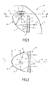
- a lighting module M for motor vehicle light projector provided to give a cut-off beam, including a beam code.
- This module has a horizontal optical axis XX and comprises at least one light source S, and a reflector R with a surface of complex type. The geometric axis of the reflector R coincides with the optical axis XX.
- Sections such as 1 of the reflector R by vertical planes parallel to the optical axis XX are substantially in parabolic arcs, turning their concavity forward, that is to say to the right according to Fig. 1 . These sections have a focus located in the horizontal plane passing through the optical axis XX of the module.
- the arc 1 corresponds to the section of the reflector R by a vertical plane passing through the optical axis XX, and has a focus F located on this axis.
- the light source S is disposed at the focus F or in its vicinity.
- the section of the reflector R by a horizontal plane passing through the optical axis is substantially in an elliptical arc 2 ( Fig. 2 ) admitting a first focus F1 coincides with the focus F or neighboring this focus, and a second focus F2 located forward on the optical axis of the module.
- the reflector R of the complex surface type produces a cut beam to the front.
- the cutoff may correspond to a flat line, in particular horizontal for an anti-fog function. It may also correspond to a flat but oblique line, in particular to participate in the formation of the oblique part of a cross-type beam (which, according to European regulations, presents a cut in the form of a broken line comprising a horizontal plane segment and an oblique plane segment at 15 °).
- a cylindrical lens L with vertical generatrices is placed between two planes passing through the foci F1 and F2 of the ellipse arc 2 and orthogonal to the optical axis.
- the lens has a general shape of a diverging lens, of which at least one zone may not be divergent.
- the light source S is constituted by at least one light-emitting diode 3, abbreviated as LED.
- the emitter of the LED 3 is of the rectangular or square plane type, with 1 to 5 mm of side.
- the focal length of the reflector R is of the order of 5 mm for such emitters.
- the LED 3 is arranged so as to illuminate downwards with the mean direction ⁇ of its light beam substantially vertical and orthogonal to the geometric axis of the reflector R.
- This reflector R is located, relative to the plane of the rear face 4 of the LED, entirely on the side of the beam emitted by the LED 3.
- the surface of the reflector R is calculated taking into account the optical protection of the LED 3.
- the leading edge of the LED 3 is located at the focus F and the LED extends rearward from the focus F.
- the collector reflector R is such that at each point of this reflector light rays such as i1 from the front edge of the LED 3 are reflected horizontally along a radius such as r1, or so as to define an oblique planar cut line up to 15 ° on the horizontal.
- the rays such as i2 emitted by LED 3 points located behind the front edge are reflected in rays such as r2 falling below the horizontal. With this arrangement, the illuminated area is therefore below a horizontal cut or an inclined cut rising on the horizontal.
- the LED 3 is then placed so that its trailing edge passes through the focus. F and LED 3 is located in front of this fireplace.
- a radiator 5 for evacuating the heat released by the LED 3 is disposed against the rear face of this LED, on the opposite side to the reflector R.
- the entire module is arranged in a box closed at the front by a transparent glass G.
- the LED 3 is arranged so that the plane of its rear face 4 is horizontal, the radiator 5 is oriented upwards.
- the reflector R is located below the horizontal plane of the rear face 4.
- the cylindrical lens L substantially divergent, can be placed anywhere between the collector reflector R and the focus F2, and adjusts the horizontal distribution of light in the beam.
- the lens La, before folding the beam must exceed the reflector up, while in the case of Fig. 1 and 2 the lens L must extend beyond the reflector downwards because the beam diverges all the more as it is further away from the reflector.
- the closer the lens L, La is to F2 the more potentially it is narrow (the width corresponds to the dimension in a direction perpendicular to the plane of Fig. 1 ) since the beam in top view converges to F2; however, this effect is partially or totally canceled depending on the source chosen and its orientation due to the divergence due to the size of the source.
- the module M of Fig. 1 and 2 offers a high yield. It makes it possible to obtain a satisfactory luminous flux for a reduced electrical energy consumption, but does not lend itself well to vertical stacking, on the one hand because of the arrangement of the radiator 5 and on the other hand because the LEDs will not be located in the same plane, which prevents them from being placed on a single circuit board and complicates the electrical connections.
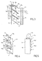
- modules can be juxtaposed horizontally, with the rear faces of the LEDs in the same horizontal plane, for mounting on a single horizontal printed circuit board.
- a module Ma comprises at least one LED 3a whose rear face 4a is located in a vertical plane 6 so as to emit forward a light beam having a substantially horizontal mean direction ⁇ a.
- the radiator 5a of the LED is located behind it while the reflector Ra is located in front of the LED with its concavity facing down.
- Geometric axis (not drawn on Fig.3 ) of the reflector Ra is vertical.
- the mean direction ⁇ a of the beam of the LED is horizontal, and therefore orthogonal to the geometric axis of the reflector Ra.
- a reflecting mirror 7 plane is disposed below the reflector Ra to return the beam to the lens La with vertical generators.
- the mirror 7 is inclined, preferably at 45 °, on the horizontal plane.
- Fig. 3 it is then possible to vertically stack several modules, for example three similar modules Ma, Ma1, Ma2 whose rear faces 4a, 4a1, 4a2 LEDs 3a, 3a1, 3a2 are located in the same vertical plane 6 and can be fixed and connected on the same vertical printed circuit board 8.
- Radiators 5a, 5a1, 5a2 are disposed behind each respective LED; alternatively the radiators could be grouped into a single common radiator.
- the LED 3a Due to the reversal of the beam created by the reflecting mirror 7, the LED 3a is arranged such that its upper edge is substantially at the focal point Fa of the reflector Ra.
- the light rays such as i3 from areas of the LED 3a located lower than the focus are reflected downwardly by Ra away outwardly, and then reflected by the mirror 7 along radii such as r3 following a downward direction.
- the lens La is common to the three modules and has a height sufficient for this purpose.
- PBL Progressive Bending Lignt
- the reflecting plane mirror 7 of a module is fixed to the back of the reflector Ra1, Ra2 of the module located below and forms a single piece with this reflector.
- the input face 9 of the lens La may have recesses at the transition zones between the different modules while the exit face 10 of this lens is smooth, without recess.
- the reflectors R, Ra, Ra1, Ra2 of "complex surface” type are adapted to the LEDs 3. Indeed, given the target focal lengths (of the order of 5 mm for light emitters of 1 to 5 mm side) , you have to take into account the protection optics of the LEDs.
- This case corresponds to a protective optics of the blade type or plate with parallel faces.
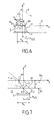
- a method for calculating the cross-sections for the two families of LEDs above (1a, 1b) is given below for a direction parallel to x (axis of the marker, itself parallel to one of the sides of the emitter ), in the case of a low cut, dead zone at the top after folding and assembly.
- the exposed calculation method is an elementary numerical solution of the underlying equation, which is a differential equation.
- a suitable tangent cylinder at any point P current of the parameter curve and thus construct the complete surface (this surface is the inner envelope - that is, the source side - of this infinity of cylinders).
- this surface is the inner envelope - that is, the source side - of this infinity of cylinders.
- one calculates a section of each of the cylinders belonging to the desired envelope, cut by a vertical plane containing P parallel to the radius coming from F1 after reflection at P.
- the calculation of the cross section of the cylinder is carried out as above after projection of F and the emitter on a vertical plane passing through P and containing the normal to the parameter curve, generally elliptical, in P. Hs and f then have different values for each point P.
- the parameter curve is an elliptical arc of F and F2 foci.
- F and F1 are merged or substantially merged, but this is only an example, and F and F1 can also be distinct.
- the output lens is constructed as a function of a horizontal deflection parameter of the images which makes it possible to control the shape of the iso illumination curves on a measurement screen and the total width of the beam.
- a horizontal deflection parameter of the images which makes it possible to control the shape of the iso illumination curves on a measurement screen and the total width of the beam.
- the principle used consists in transforming a spherical wave coming from a corner of the emitter (F, as above) into a spherical wave of center F2.
- the calculation obviously takes into account the deviations due to the protective dome (which is not centered on the focus).
- the procedure is relatively simple, which comes from the fact that it is desired to make a low-cut beam, regardless of the choice of a beam converging in a top view towards F2.
Landscapes
- Engineering & Computer Science (AREA)
- General Engineering & Computer Science (AREA)
- Physics & Mathematics (AREA)
- Microelectronics & Electronic Packaging (AREA)
- Optics & Photonics (AREA)
- Geometry (AREA)
- Non-Portable Lighting Devices Or Systems Thereof (AREA)
- Led Device Packages (AREA)
Applications Claiming Priority (1)
| Application Number | Priority Date | Filing Date | Title |
|---|---|---|---|
| FR0705535A FR2919378B1 (fr) | 2007-07-27 | 2007-07-27 | Module d'eclairage pour projecteur de vehicule automobile. |
Publications (1)
| Publication Number | Publication Date |
|---|---|
| EP2019256A1 true EP2019256A1 (de) | 2009-01-28 |
Family
ID=39125220
Family Applications (1)
| Application Number | Title | Priority Date | Filing Date |
|---|---|---|---|
| EP08160944A Withdrawn EP2019256A1 (de) | 2007-07-27 | 2008-07-23 | Beleuchtungsmodul für Kraftfahrzeugscheinwerfer |
Country Status (4)
| Country | Link |
|---|---|
| US (1) | US7980742B2 (de) |
| EP (1) | EP2019256A1 (de) |
| JP (1) | JP2009059689A (de) |
| FR (1) | FR2919378B1 (de) |
Cited By (4)
| Publication number | Priority date | Publication date | Assignee | Title |
|---|---|---|---|---|
| EP2278217A1 (de) * | 2009-07-21 | 2011-01-26 | Valeo Vision | Beleuchtungsmodul für Fahrzeugscheinwerfer, und mit wenigstens einem solchen Modul ausgerüsteter Scheinwerfer |
| EP2858467A1 (de) * | 2013-09-30 | 2015-04-08 | Goodrich Corporation | Lokalisierung optischer Strukturen an LEDs |
| CN115638383A (zh) * | 2022-10-31 | 2023-01-24 | 常州星宇车灯股份有限公司 | 反射式光学模组及使用其的照明装置及车辆 |
| WO2024033122A1 (fr) * | 2022-08-12 | 2024-02-15 | Valeo Vision | Projecteur á coupure et étendu verticalement pour véhicule automobile |
Families Citing this family (13)
| Publication number | Priority date | Publication date | Assignee | Title |
|---|---|---|---|---|
| WO2012162927A1 (zh) * | 2011-06-02 | 2012-12-06 | 天津方合科技发展有限公司 | 近光带有明暗截止线的汽车前照灯led光学组件 |
| DE102012220455A1 (de) * | 2012-11-09 | 2014-05-15 | Osram Gmbh | Leuchtvorrichtung mit halbleiterlichtquelle |
| USD762324S1 (en) | 2014-06-08 | 2016-07-26 | Valeo North America, Inc. | Stylized signature lamp |
| EP3152481A1 (de) | 2014-06-08 | 2017-04-12 | Valeo North America, LLC | Beleuchtungsvorrichtung mit reflektoren und linse zur erzeugung eines lichtmusters mit grenzlinie |
| US10386032B2 (en) | 2014-07-15 | 2019-08-20 | Koninklijke Philips N.V. | Vehicle lighting module |
| JP2016181388A (ja) * | 2015-03-24 | 2016-10-13 | スタンレー電気株式会社 | 車両用灯具 |
| FR3039630A1 (fr) * | 2015-07-28 | 2017-02-03 | Valeo Vision | Systeme d'eclairage pour projecteur de vehicule automobile |
| FR3063795B1 (fr) * | 2017-03-13 | 2019-04-05 | Valeo Vision | Dispositif lumineux, notamment d'eclairage et/ou de signalisation, pour vehicule automobile |
| US20210356090A1 (en) * | 2018-07-20 | 2021-11-18 | Hasco Vision Technology Co., Ltd. | Projection unit for low beam light of vehicle and vehicle lamp using same |
| FR3118123B1 (fr) * | 2020-12-18 | 2023-04-28 | Valeo Vision | Dispositif d’éclairage de véhicule automobile |
| KR20240063649A (ko) * | 2022-11-03 | 2024-05-10 | 현대모비스 주식회사 | 차량용 램프 |
| CN116146930B (zh) * | 2023-03-01 | 2026-03-06 | 曼德电子电器有限公司 | 光学透镜模组及车灯 |
| EP4621285A1 (de) * | 2024-03-21 | 2025-09-24 | ZKW Group GmbH | Beleuchtungsvorrichtung für ein kraftfahrzeug |
Citations (6)
| Publication number | Priority date | Publication date | Assignee | Title |
|---|---|---|---|---|
| EP1225386A2 (de) * | 2001-01-22 | 2002-07-24 | Ichikoh Industries, Ltd. | Fahrzeugscheinwefer |
| EP1243846A1 (de) | 2001-03-21 | 2002-09-25 | Valeo Vision | Kraftfahrzeugprojektor mit Spiegel und konjugiertem Umlenkelement und Verfahren zur Herstellung desselben |
| EP1491816A1 (de) | 2003-06-27 | 2004-12-29 | Valeo Vision | Kfz-Scheinwerfer mit einem Spiegel und einem optischen Umlenkelement |
| EP1500553A1 (de) | 2003-07-24 | 2005-01-26 | Valeo Vision | Starrer Kurvenscheinwerfer für Kraftfahrzeuge |
| FR2868510A1 (fr) * | 2004-04-02 | 2005-10-07 | Koito Mfg Co Ltd | Lampe d'eclairage a diodes electroluminescentes pour vehicule |
| US20060239022A1 (en) * | 2005-04-21 | 2006-10-26 | Koito Manufacturing Co., Ltd. | Projector-type lamp unit for vehicle |
Family Cites Families (1)
| Publication number | Priority date | Publication date | Assignee | Title |
|---|---|---|---|---|
| JP4468857B2 (ja) * | 2005-05-17 | 2010-05-26 | 株式会社小糸製作所 | 車両用照明灯具 |
-
2007
- 2007-07-27 FR FR0705535A patent/FR2919378B1/fr not_active Expired - Fee Related
-
2008
- 2008-07-23 EP EP08160944A patent/EP2019256A1/de not_active Withdrawn
- 2008-07-24 US US12/178,825 patent/US7980742B2/en not_active Expired - Fee Related
- 2008-07-25 JP JP2008191554A patent/JP2009059689A/ja active Pending
Patent Citations (6)
| Publication number | Priority date | Publication date | Assignee | Title |
|---|---|---|---|---|
| EP1225386A2 (de) * | 2001-01-22 | 2002-07-24 | Ichikoh Industries, Ltd. | Fahrzeugscheinwefer |
| EP1243846A1 (de) | 2001-03-21 | 2002-09-25 | Valeo Vision | Kraftfahrzeugprojektor mit Spiegel und konjugiertem Umlenkelement und Verfahren zur Herstellung desselben |
| EP1491816A1 (de) | 2003-06-27 | 2004-12-29 | Valeo Vision | Kfz-Scheinwerfer mit einem Spiegel und einem optischen Umlenkelement |
| EP1500553A1 (de) | 2003-07-24 | 2005-01-26 | Valeo Vision | Starrer Kurvenscheinwerfer für Kraftfahrzeuge |
| FR2868510A1 (fr) * | 2004-04-02 | 2005-10-07 | Koito Mfg Co Ltd | Lampe d'eclairage a diodes electroluminescentes pour vehicule |
| US20060239022A1 (en) * | 2005-04-21 | 2006-10-26 | Koito Manufacturing Co., Ltd. | Projector-type lamp unit for vehicle |
Cited By (8)
| Publication number | Priority date | Publication date | Assignee | Title |
|---|---|---|---|---|
| EP2278217A1 (de) * | 2009-07-21 | 2011-01-26 | Valeo Vision | Beleuchtungsmodul für Fahrzeugscheinwerfer, und mit wenigstens einem solchen Modul ausgerüsteter Scheinwerfer |
| FR2948439A1 (fr) * | 2009-07-21 | 2011-01-28 | Valeo Vision | Module d'eclairage pour projecteur de vehicule automobile, et projecteur equipe d'au moins un tel module. |
| EP3073185A1 (de) * | 2009-07-21 | 2016-09-28 | Valeo Vision | Beleuchtungsmodul für scheinwerfer von kraftfahrzeugen, sowie scheinwerfer, der mit mindestens einem solchen modul ausgestattet ist |
| EP2858467A1 (de) * | 2013-09-30 | 2015-04-08 | Goodrich Corporation | Lokalisierung optischer Strukturen an LEDs |
| WO2024033122A1 (fr) * | 2022-08-12 | 2024-02-15 | Valeo Vision | Projecteur á coupure et étendu verticalement pour véhicule automobile |
| FR3138789A1 (fr) * | 2022-08-12 | 2024-02-16 | Valeo Vision | Projecteur á coupure et étendu verticalement pour véhicule automobile |
| US12601456B2 (en) | 2022-08-12 | 2026-04-14 | Valeo Vision | Headlamp having a vertical cut-off and extension for a motor vehicle |
| CN115638383A (zh) * | 2022-10-31 | 2023-01-24 | 常州星宇车灯股份有限公司 | 反射式光学模组及使用其的照明装置及车辆 |
Also Published As
| Publication number | Publication date |
|---|---|
| FR2919378A1 (fr) | 2009-01-30 |
| FR2919378B1 (fr) | 2009-10-23 |
| US7980742B2 (en) | 2011-07-19 |
| JP2009059689A (ja) | 2009-03-19 |
| US20090027909A1 (en) | 2009-01-29 |
Similar Documents
| Publication | Publication Date | Title |
|---|---|---|
| EP2019256A1 (de) | Beleuchtungsmodul für Kraftfahrzeugscheinwerfer | |
| EP3232118B1 (de) | Scheinwerfer für ein kraftfahrzeug | |
| EP4235024B1 (de) | Leuchtvorrichtung, die die beleuchteten flächen von mindestens zwei kollektoren abbildet | |
| EP2045515B1 (de) | Vorrichtung zur Beleuchtung oder Signalisierung für Kraftfahrzeuge | |
| EP1500869B1 (de) | Elliptische Beleuchtungseinheit ohne Lichtblende zur Erzeugung eines Abblendlichtbündels und Scheinwerfer mit einer derartigen Belleuchtungseinheit | |
| EP3124854B1 (de) | Beleuchtungssystem für kraftfahrzeugscheinwerfer | |
| EP1357334B1 (de) | Elliptische Beleuchtungsbaugruppe ohne Lichtblende zur Erzeugung eines Abblendlichtes und Scheinwerfer mit einer derartigen Beleuchtungsbaugruppe | |
| EP1965126B1 (de) | Scheinwerfer für Kraftfahrzeug | |
| EP1843085A1 (de) | Beleuchtungsmodul für Scheinwerfer eine Motorfahrzeugts und Scheinwerfer, der ein solches Modul umfasst | |
| FR3032778A1 (fr) | Feu de vehicule | |
| FR3010772A1 (fr) | Dispositif d'emission de lumiere pour projecteur de vehicule automobile | |
| EP3246620A1 (de) | Led-scheinwerfer für fahrzeuge mit diopter, der eine abschattung erzeugt | |
| FR2878938A1 (fr) | Module d'eclairage pour projecteur de vehicule automobile | |
| FR3036162A1 (fr) | Module d'eclairage bifonction code - route pour vehicule automobile | |
| EP3115683A1 (de) | Leuchtmodul zur beleuchtung und/oder signalisierung für kraftfahrzeug | |
| FR3093788A1 (fr) | Dispositif lumineux imageant une surface eclairee virtuelle d’un collecteur | |
| WO2022129420A1 (fr) | Module lumineux imageant la surface eclairee d'un collecteur avec bloqueur de rayons parasites | |
| FR2755210A1 (fr) | Projecteur a conduit de lumiere pour vehicules automobiles | |
| EP1489351B1 (de) | Fahrzeugscheinwerfer mit mindestens zwei Funktionen | |
| EP2416061A2 (de) | Beleuchtungsmodul mit Abschaltfunktion mit einem Parabolreflektor, der auf einem elliptischen Reflektor angebracht ist | |
| EP2101105B1 (de) | Beleuchtungsvorrichtung für Kraftfahrzeug | |
| EP2366941A2 (de) | Beleuchtungsmodul mit zwei Scheinwerfern mit unterschiedlichen Brennpunktabständen | |
| WO2024061970A1 (fr) | Module lumineux | |
| FR3127547A1 (fr) | Module lumineux à sources à partie émissive maximisée | |
| FR2757605A1 (fr) | Barreau optique pour projecteur de vehicule automobile |
Legal Events
| Date | Code | Title | Description |
|---|---|---|---|
| PUAI | Public reference made under article 153(3) epc to a published international application that has entered the european phase |
Free format text: ORIGINAL CODE: 0009012 |
|
| AK | Designated contracting states |
Kind code of ref document: A1 Designated state(s): AT BE BG CH CY CZ DE DK EE ES FI FR GB GR HR HU IE IS IT LI LT LU LV MC MT NL NO PL PT RO SE SI SK TR |
|
| AX | Request for extension of the european patent |
Extension state: AL BA MK RS |
|
| 17P | Request for examination filed |
Effective date: 20090720 |
|
| 17Q | First examination report despatched |
Effective date: 20090825 |
|
| AKX | Designation fees paid |
Designated state(s): AT BE BG CH CY CZ DE DK EE ES FI FR GB GR HR HU IE IS IT LI LT LU LV MC MT NL NO PL PT RO SE SI SK TR |
|
| STAA | Information on the status of an ep patent application or granted ep patent |
Free format text: STATUS: THE APPLICATION IS DEEMED TO BE WITHDRAWN |
|
| 18D | Application deemed to be withdrawn |
Effective date: 20171024 |
|
| RIC1 | Information provided on ipc code assigned before grant |
Ipc: F21Y 101/02 20000101ALN20081023BHEP Ipc: F21W 101/10 20060101ALN20081023BHEP Ipc: F21S 8/10 20060101AFI20081023BHEP |