EP2019273A1 - Mécanisme de réfrigération - Google Patents
Mécanisme de réfrigération Download PDFInfo
- Publication number
- EP2019273A1 EP2019273A1 EP07743586A EP07743586A EP2019273A1 EP 2019273 A1 EP2019273 A1 EP 2019273A1 EP 07743586 A EP07743586 A EP 07743586A EP 07743586 A EP07743586 A EP 07743586A EP 2019273 A1 EP2019273 A1 EP 2019273A1
- Authority
- EP
- European Patent Office
- Prior art keywords
- pipe
- heat
- temperature
- pressure sensor
- suction
- Prior art date
- Legal status (The legal status is an assumption and is not a legal conclusion. Google has not performed a legal analysis and makes no representation as to the accuracy of the status listed.)
- Withdrawn
Links
Images


Classifications
-
- F—MECHANICAL ENGINEERING; LIGHTING; HEATING; WEAPONS; BLASTING
- F25—REFRIGERATION OR COOLING; COMBINED HEATING AND REFRIGERATION SYSTEMS; HEAT PUMP SYSTEMS; MANUFACTURE OR STORAGE OF ICE; LIQUEFACTION SOLIDIFICATION OF GASES
- F25B—REFRIGERATION MACHINES, PLANTS OR SYSTEMS; COMBINED HEATING AND REFRIGERATION SYSTEMS; HEAT PUMP SYSTEMS
- F25B13/00—Compression machines, plants or systems, with reversible cycle
-
- F—MECHANICAL ENGINEERING; LIGHTING; HEATING; WEAPONS; BLASTING
- F25—REFRIGERATION OR COOLING; COMBINED HEATING AND REFRIGERATION SYSTEMS; HEAT PUMP SYSTEMS; MANUFACTURE OR STORAGE OF ICE; LIQUEFACTION SOLIDIFICATION OF GASES
- F25B—REFRIGERATION MACHINES, PLANTS OR SYSTEMS; COMBINED HEATING AND REFRIGERATION SYSTEMS; HEAT PUMP SYSTEMS
- F25B49/00—Arrangement or mounting of control or safety devices
- F25B49/02—Arrangement or mounting of control or safety devices for compression type machines, plants or systems
-
- F—MECHANICAL ENGINEERING; LIGHTING; HEATING; WEAPONS; BLASTING
- F25—REFRIGERATION OR COOLING; COMBINED HEATING AND REFRIGERATION SYSTEMS; HEAT PUMP SYSTEMS; MANUFACTURE OR STORAGE OF ICE; LIQUEFACTION SOLIDIFICATION OF GASES
- F25B—REFRIGERATION MACHINES, PLANTS OR SYSTEMS; COMBINED HEATING AND REFRIGERATION SYSTEMS; HEAT PUMP SYSTEMS
- F25B41/00—Fluid-circulation arrangements
- F25B41/40—Fluid line arrangements
-
- F—MECHANICAL ENGINEERING; LIGHTING; HEATING; WEAPONS; BLASTING
- F25—REFRIGERATION OR COOLING; COMBINED HEATING AND REFRIGERATION SYSTEMS; HEAT PUMP SYSTEMS; MANUFACTURE OR STORAGE OF ICE; LIQUEFACTION SOLIDIFICATION OF GASES
- F25B—REFRIGERATION MACHINES, PLANTS OR SYSTEMS; COMBINED HEATING AND REFRIGERATION SYSTEMS; HEAT PUMP SYSTEMS
- F25B2313/00—Compression machines, plants or systems with reversible cycle not otherwise provided for
- F25B2313/006—Compression machines, plants or systems with reversible cycle not otherwise provided for two pipes connecting the outdoor side to the indoor side with multiple indoor units
-
- F—MECHANICAL ENGINEERING; LIGHTING; HEATING; WEAPONS; BLASTING
- F25—REFRIGERATION OR COOLING; COMBINED HEATING AND REFRIGERATION SYSTEMS; HEAT PUMP SYSTEMS; MANUFACTURE OR STORAGE OF ICE; LIQUEFACTION SOLIDIFICATION OF GASES
- F25B—REFRIGERATION MACHINES, PLANTS OR SYSTEMS; COMBINED HEATING AND REFRIGERATION SYSTEMS; HEAT PUMP SYSTEMS
- F25B2313/00—Compression machines, plants or systems with reversible cycle not otherwise provided for
- F25B2313/023—Compression machines, plants or systems with reversible cycle not otherwise provided for using multiple indoor units
- F25B2313/0233—Compression machines, plants or systems with reversible cycle not otherwise provided for using multiple indoor units in parallel arrangements
-
- F—MECHANICAL ENGINEERING; LIGHTING; HEATING; WEAPONS; BLASTING
- F25—REFRIGERATION OR COOLING; COMBINED HEATING AND REFRIGERATION SYSTEMS; HEAT PUMP SYSTEMS; MANUFACTURE OR STORAGE OF ICE; LIQUEFACTION SOLIDIFICATION OF GASES
- F25B—REFRIGERATION MACHINES, PLANTS OR SYSTEMS; COMBINED HEATING AND REFRIGERATION SYSTEMS; HEAT PUMP SYSTEMS
- F25B2313/00—Compression machines, plants or systems with reversible cycle not otherwise provided for
- F25B2313/027—Compression machines, plants or systems with reversible cycle not otherwise provided for characterised by the reversing means
- F25B2313/02741—Compression machines, plants or systems with reversible cycle not otherwise provided for characterised by the reversing means using one four-way valve
-
- F—MECHANICAL ENGINEERING; LIGHTING; HEATING; WEAPONS; BLASTING
- F25—REFRIGERATION OR COOLING; COMBINED HEATING AND REFRIGERATION SYSTEMS; HEAT PUMP SYSTEMS; MANUFACTURE OR STORAGE OF ICE; LIQUEFACTION SOLIDIFICATION OF GASES
- F25B—REFRIGERATION MACHINES, PLANTS OR SYSTEMS; COMBINED HEATING AND REFRIGERATION SYSTEMS; HEAT PUMP SYSTEMS
- F25B2500/00—Problems to be solved
- F25B2500/01—Geometry problems, e.g. for reducing size
-
- F—MECHANICAL ENGINEERING; LIGHTING; HEATING; WEAPONS; BLASTING
- F25—REFRIGERATION OR COOLING; COMBINED HEATING AND REFRIGERATION SYSTEMS; HEAT PUMP SYSTEMS; MANUFACTURE OR STORAGE OF ICE; LIQUEFACTION SOLIDIFICATION OF GASES
- F25B—REFRIGERATION MACHINES, PLANTS OR SYSTEMS; COMBINED HEATING AND REFRIGERATION SYSTEMS; HEAT PUMP SYSTEMS
- F25B2700/00—Sensing or detecting of parameters; Sensors therefor
- F25B2700/19—Pressures
- F25B2700/193—Pressures of the compressor
- F25B2700/1931—Discharge pressures
-
- F—MECHANICAL ENGINEERING; LIGHTING; HEATING; WEAPONS; BLASTING
- F25—REFRIGERATION OR COOLING; COMBINED HEATING AND REFRIGERATION SYSTEMS; HEAT PUMP SYSTEMS; MANUFACTURE OR STORAGE OF ICE; LIQUEFACTION SOLIDIFICATION OF GASES
- F25B—REFRIGERATION MACHINES, PLANTS OR SYSTEMS; COMBINED HEATING AND REFRIGERATION SYSTEMS; HEAT PUMP SYSTEMS
- F25B2700/00—Sensing or detecting of parameters; Sensors therefor
- F25B2700/19—Pressures
- F25B2700/193—Pressures of the compressor
- F25B2700/1933—Suction pressures
-
- F—MECHANICAL ENGINEERING; LIGHTING; HEATING; WEAPONS; BLASTING
- F25—REFRIGERATION OR COOLING; COMBINED HEATING AND REFRIGERATION SYSTEMS; HEAT PUMP SYSTEMS; MANUFACTURE OR STORAGE OF ICE; LIQUEFACTION SOLIDIFICATION OF GASES
- F25D—REFRIGERATORS; COLD ROOMS; ICE-BOXES; COOLING OR FREEZING APPARATUS NOT OTHERWISE PROVIDED FOR
- F25D29/00—Arrangement or mounting of control or safety devices
- F25D29/005—Mounting of control devices
Definitions
- This invention relates to refrigeration systems including a refrigerant circuit operating in a vapor compression refrigeration cycle and particularly relates to a mounting structure of a suction pressure sensor for measuring the suction pressure of a compression mechanism.
- Refrigeration systems are conventionally known that include a refrigerant circuit operating in a refrigeration cycle and chill or freeze stored goods in a cold storage (see, for example, Patent Document 1).
- the refrigeration system disclosed in Patent Document 1 includes a cooling heat exchanger for freezing, a low-pressure stage compressor, a high-pressure stage compressor, an outdoor heat exchanger and a freezing expansion valve that are connected in this order.
- refrigerant compressed in two stages by the low-pressure stage compressor and the high-pressure stage compressor releases heat at the outdoor heat exchanger to condense into liquid form.
- the liquefied refrigerant expands in the freezing expansion valve, flows through the cooling heat exchanger for freezing, and takes heat therein from the in-storage air to evaporate, for example, at -30°C and thereby cool the interior of the cold storage down to -20°C.
- the evaporated refrigerant is sucked into the low-pressure stage compressor again. Thereafter, this circulation is repeated.
- the suction pipes of the low-pressure stage and high-pressure stage compressors are provided with their respective suction pressure sensors for measuring the suction pressures of the compressors.
- the suction pipe (a) of each compressor is connected to a thin pipe (c) and the distal end of the thin pipe (c) is externally threaded to connect a pressure sensor (b) thereat.
- the pressure sensor (b) includes an internally threaded connecting part (d) and is connected to the suction pipe (a) by engaging the internal threads of the connecting part (d) on the external threads of the thin pipe (c) .
- the present invention has been made in view of the foregoing points and, therefore, an object thereof is that a refrigeration system including a suction pressure sensor for measuring the suction pressure of a compression mechanism can enhance the workability in mounting and replacing the pressure sensor and enhance the reliability of the pressure sensor.
- a first aspect of the invention is directed to a refrigeration system including a refrigerant circuit (10) in which an evaporator (16, 17) , a compression mechanism (11) , a condenser (13) and an expansion mechanism (15a, 15b) are connected in this order and further including a suction pressure sensor (25) for measuring the suction pressure of the compression mechanism (11), wherein the suction pressure sensor (25) is connected to a suction pipe (61) of the compression mechanism (11) through a heat taking pipe (90) for making the temperature of a connecting part (25b) of the suction pressure sensor (25) higher than the temperature of the suction pipe (61) .
- refrigerant having flowed through the evaporator (16, 17) flows through the suction pipe (61) . Therefore, when the set temperature of the evaporator (16, 17) is low (at 0°C or lower), low-temperature refrigerant at 0°C or lower flows also through the suction pipe (61) of the compression mechanism (11) .
- the suction pressure sensor (25) is attached to the suction pipe (61) through the heat taking pipe (90) .
- the cold heat of refrigerant flowing through the suction pipe (61) becomes less likely to be transmitted to the connecting part (25b) of the suction pressure sensor (25) .
- the heat taking pipe (90) takes heat such as from the ambient air to keep the temperature of the connecting part ( 25b) of the suction pressure sensor (25) at a higher temperature than 0°C, thereby preventing the connecting part (25b) from freezing.
- a second aspect of the invention is the refrigeration system according to the first aspect of the invention, wherein the heat taking pipe (90) is formed with a length with which the connecting part (25b) of the suction pressure sensor (25) reaches a higher temperature than the suction pipe (61) owing to the ambient temperature.
- the heat taking pipe (90) takes heat from the ambient air to gradually increase its temperature from the suction pipe (61) to the connecting part (25b) of the suction pressure sensor (25) , so that the connecting part (25b) of the suction pressure sensor (25) reaches a higher temperature than 0°C.
- a third aspect of the invention is the refrigeration system according to the second aspect of the invention, wherein the minimum length of the heat taking pipe (90) is set to a predetermined length increasing as the evaporation temperature in the evaporator (16, 17) decreases.
- the minimum length of the heat taking pipe (90) is increased with decreasing evaporation temperature in the evaporator (17, 17) .
- the temperature of refrigerant flowing through the suction pipe (61) decreases, the cold heat of the refrigerant becomes less likely to be transmitted to the connecting part (25b) of the suction pressure sensor (25) .
- the area of the heat taking pipe (90) is increased, the amount of heat that the heat taking pipe (90) takes such as from the ambient air can be increased.
- a fourth aspect of the invention is the refrigeration system according to any one of the first to third aspects of the invention, wherein the heat taking pipe (90) is attached through a heat transfer member (91) to a high-pressure side pipe (64) of the refrigerant circuit (10) .
- heat of the high-pressure side pipe (64) is transmitted through the heat transfer member (91) .
- the amount of heat taken by the heat taking pipe (90) increases, so that the connecting part (25b) of the suction pressure sensor (25) reaches a higher temperature than 0°C.
- the high-pressure side pipe (64) in the fourth aspect of the invention is a pipe through which refrigerant having a higher pressure than refrigerant in the suction pipe (61) and a higher temperature than 0°C flows.
- a fifth aspect of the invention is the refrigeration system according to the fourth aspect of the invention, wherein the high-pressure side pipe (64) is a discharge pipe (64) of the compression mechanism (11).
- the amount of heat taken from the high-pressure side pipe (64) through the heat transfer member (91) by the heat taking pipe (90) increases as the temperature of the high-pressure side pipe (64) increases.
- the heat taking pipe (90) since the heat taking pipe (90) is joined through the heat transfer member (91) to the high-temperature discharge pipe (64) of the compression mechanism (11) , the amount of heat taken by the heat taking pipe (90) can be surely increased.
- the heat taking pipe (90) can make it difficult to transmit the cold heat of refrigerant flowing through the suction pipe (61) to the connecting part (25b) of the suction pressure sensor (25) and can take heat such as from the ambient air.
- the connecting part (25b) of the suction pressure sensor (25) can have a higher temperature than 0°C.
- the connecting part (25b) of the suction pressure sensor (25) can be prevented from breakage due to freezing, which enhances the reliability of the suction pressure sensor (25) .
- suction pressure sensor (25) can be prevented from breakage without silicone filling or brazing, the workability of mounting and replacement of the suction pressure sensor (25) can be enhanced as compared with conventional measures for preventing its breakage.
- the heat taking pipe (90) since the heat taking pipe (90) is formed with a length with which the connecting part (25b) of the suction pressure sensor (25) reaches a higher temperature than the suction pipe (61) owing to the ambient temperature, the heat taking pipe (90) can take heat from the ambient air to gradually increase its temperature from the suction pipe (61) to the connecting part (25b) of the suction pressure sensor (25) .
- the connecting part (25b) of the suction pressure sensor (25) can have a higher temperature than 0°C.
- the minimum length of the heat taking pipe (90) is set to a predetermined length increasing as the evaporation temperature in the evaporator (16, 17) decreases, the cold heat of refrigerant flowing through the suction pipe (61) can be less likely to be transmitted to the connecting part (25b) of the suction pressure sensor (25) as the temperature of the refrigerant decreases.
- the connecting part (25b) of the suction pressure sensor (25) can surely reach a higher temperature than 0°C according to the set temperature of the evaporator (16, 17) .
- the heat taking pipe (90) can take heat from the high-pressure side pipe (64) of the refrigerant circuit (10) through the heat transfer member (91) , the amount of heat taken by the heat taking pipe (90) can be increased.
- the connecting part (25b) of the suction pressure sensor (25) can have a higher temperature than 0°C.
- the heat taking pipe (90) can take heat from the discharge pipe (64) of the compression mechanism (11) through the heat transfer member (91) , the amount of heat taken by the heat taking pipe (90) can surely be increased because the discharge pipe (64) of the compression mechanism (11) has a high temperature.
- the connecting part (25b) of the suction pressure sensor (25) can surely reach a higher temperature than 0°C.
- the embodiment of the present invention is a refrigeration system (1) for cooling a cooling room and the refrigeration system (1) includes an outdoor unit (2) , a chilling unit (3) and a controller (100) .
- the outdoor unit (2) is placed outdoors and the chilling unit (3) is placed in the cooling room.
- the outdoor unit (2) includes an outdoor circuit (20) and the chilling unit (3) includes an in-chiller circuit (30) .
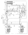
- the gas-side end of the outdoor circuit (20) is connected through a gas-side connection pipe (22) to the gas-side end of the in-chiller circuit (30) and the liquid-side end of the outdoor circuit (20) is connected through a liquid-side connection pipe (21) to the liquid-side end of the in-chiller circuit (30), whereby a refrigerant circuit (10) operable in a vapor compression refrigeration cycle is constituted.
- the outdoor circuit (20) of the outdoor unit (2) includes a compressor (11) , an outdoor heat exchanger (13) , a receiver (14) , an outdoor expansion valve (45) , a refrigerant heat exchanger (50) and a branch expansion valve (46) .
- the outdoor circuit (20) further includes a four-way selector valve (12), a liquid-side shut-off valve (53) and a gas-side shut-off valve (54) .
- the liquid-side shut-off valve (53) is connected to one end of the liquid-side connection pipe (21) and the gas-side shut-off valve (54) is connected to one end of the gas-side connection pipe (22) .
- the compressor (11) is a scroll compressor and is configured to be variable in operating capacity by inverter control.
- the suction side of the compressor (11) is connected to one end of a suction pipe (61) and the other end of the suction pipe (61) is connected to the four-way selector valve (12) .
- the discharge side of the compressor (11) is connected to one end of a discharge pipe (64) and the other end of the discharge pipe (64) is connected to the four-way selector valve (12) .
- the outdoor heat exchanger (13) is a cross-fin type fin-and-tube heat exchanger for exchanging heat between refrigerant and outside air and is formed into a condenser.
- One end of the outdoor heat exchanger (13) is connected to the four-way selector valve (12) .
- the other end of the outdoor heat exchanger (13) is connected through a first liquid pipe (81) to the top of the receiver (14).
- the first liquid pipe (81) includes a check valve (CV-1) for allowing only the refrigerant flow from the outdoor heat exchanger (13) to the receiver (14) .
- the bottom of the receiver (14) is connected to one end of a second liquid pipe (82) .
- the refrigerant heat exchanger (50) is a plate type heat exchanger for exchanging heat between refrigerant and refrigerant and includes a first channel (50a) and a second channel (50b).
- the entrance side of the first channel (50a) of the refrigerant heat exchanger (50) is connected to the other end of the second liquid pipe (82)
- the exit side of the first channel (50a) is connected to one end of a third liquid pipe (83) .
- the other end of the third liquid pipe (83) is connected through the liquid-side shut-off valve (53) to one end of the liquid-side connection pipe (21) .
- the third liquid pipe (83) includes a check valve (CV-2) for allowing only the refrigerant flow from the first channel (50a) to the liquid-side shut-off valve (53).
- the third liquid pipe (83) is connected, upstream of the check valve (CV-2), to one end of a branch liquid pipe (84) , and the other end of the branch liquid pipe (84) is connected to the entrance side of the second channel (50b) of the refrigerant heat exchanger (50) .
- the branch liquid pipe (84) includes the branch expansion valve (46) .
- the branch expansion valve (46) is an electronic expansion valve regulatable in opening.
- the exit side of the second channel (50b) of the refrigerant heat exchanger (50) is connected to one end of an injection pipe (85).
- the other end of the injection pipe (85) is connected to a portion of the suction pipe (61) located between the four-way selector valve (12) and the compressor (11) .
- the third liquid pipe (83) is connected, between the check valve (CV-2) and the liquid-side shut-off valve (53) , to one end of a fourth liquid pipe (88) .
- the other end of the fourth liquid pipe (88) is connected to a portion of the first liquid pipe (81) located between the check valve (CV-1) and the receiver (14) .
- the fourth liquid pipe (88) includes a check valve (CV-3) for allowing only the refrigerant flow from the third liquid pipe (83) to the receiver (14).
- the branch liquid pipe (84) is connected, between the third liquid pipe (83) and the branch expansion valve (46) , to one end of a fifth liquid pipe (89) , and the other end of the fifth liquid pipe (89) is connected to a portion of the first liquid pipe (81) located between the other end of the outdoor heat exchanger (13) and the check valve (CV-1).
- the fifth liquid pipe (89) includes the outdoor expansion valve (45) .
- the four-way selector valve (12) is connected at its first port to the discharge pipe (64) , connected at its second port to the suction pipe (61) , connected at its third port to one end of the outdoor heat exchanger (13) and connected at its fourth port to the gas-side shut-off valve (54) .
- the four-way selector valve (12) is configured to be switchable between a first position (the position shown in the solid lines in Figure 1 ) in which the first and third ports are communicated with each other and the second and fourth ports are communicated with each other and a second position (the position shown in the broken lines in Figure 1 ) in which the first and fourth ports are communicated with each other and the second and third ports are communicated with each other.
- the outdoor circuit (20) further includes an oil separator (70) and an oil return pipe (71) .
- the oil separator (70) is provided in the discharge pipe (64) and configured to separate refrigerating machine oil from gas discharged from the compressor (11) .
- the oil separator (70) is connected to one end of the oil return pipe (71) , and the other end of the oil return pipe (71) is connected to a portion of the suction pipe (61) located between the junction with the injection pipe (85) and the compressor (11) .
- the oil return pipe (71) includes a capillary tube (72) for regulating the flow rate of refrigerating machine oil.
- the suction pipe (61) of the compressor (11) is provided, between the junction with the injection pipe (85) and the junction with the oil return pipe (71) , with a suction temperature sensor (24) and a suction pressure sensor (25) in this order.
- the suction pressure sensor (25) is connected through a heat taking pipe (90) to the suction pipe (61) , which is a feature of the present invention.
- the discharge side of the compressor (11) is provided with a discharge pressure sensor (23) and a discharge temperature sensor (19) .
- the exit side of the first channel (50a) of the refrigerant heat exchanger (50) is provided with a temperature sensor (51) .
- the outdoor unit (2) includes an outside air temperature sensor (13a) and an outdoor fan (13f). Outside air is sent to the outdoor heat exchanger (13) by the outdoor fan (13f).
- the in-chiller circuit (30) of the chilling unit (3) includes two chilling heat exchangers (16, 17) and two drain pan heaters (26, 27).
- the chilling heat exchangers (16, 17) are cross-fin type fin-and-tube heat exchangers for exchanging heat between refrigerant and air in the cooling room and are each formed into an evaporator.
- One ends of the chilling heat exchangers (16, 17) are connected through respective pipes to respective chilling expansion valves (15a, 15b) .
- the other ends of the chilling heat exchangers (16, 17) are connected to respective one ends of gas-side branch pipes (22a, 22b) , and the other ends of the gas-side branch pipes (22a, 22b) join together and are connected to the other end of the gas-side connection pipes (22) .
- the chilling expansion valves (15a, 15b) are electronic expansion valves configured to be regulatable in opening and are each formed into an expansion mechanism.
- the chilling heat exchangers (16, 17) are provided with respective first refrigerant temperature sensors (16b, 17b) , and the other ends of the chilling heat exchangers (16, 17) are provided with respective second refrigerant temperature sensors (18a, 18b) .
- the first refrigerant temperature sensors (16b, 17b) are sensors for measuring the evaporation temperatures of refrigerant in their respective chilling heat exchangers (16, 17) .
- Each of the chilling expansion valves (15a, 15b) is configured so that, during the cooling operation, its opening is controlled to make the measured temperature at the associated second refrigerant temperature sensor (18a, 18b) a predetermined temperature (for example, 5°C) higher than the evaporation temperature of refrigerant measured by the associated first refrigerant temperature sensor (16b, 17b) .
- the drain pan heaters (26, 27) are disposed on respective unshown drain pans to prevent frosting and icing on the drain pans by allowing high-temperature and high-pressure refrigerant to flow through them to heat the drain pans.
- One ends of the drain pan heaters (26, 27) are connected to respective one ends of liquid-side branch pipes (21a, 21b) , and the other ends of the liquid-side branch pipes (21a, 21b) join together and are connected to the other end of the liquid-side connection pipe (21).
- the other ends of the drain pan heaters (26, 27) are connected to respective one ends of the chilling expansion valves (15a, 15b) .
- the chilling unit (3) includes cooling room temperature sensors (16a, 17a) and cooling room fans (16f, 17f). Air in the cooling room is sent to the chilling heat exchangers (16, 17) by the respective cooling room fans (16f, 17f).
- the controller (100) switches the various valves provided in the refrigerant circuit (10) and controls their openings to control the cooling operation of keeping the cooling room at a set temperature and the defrosting operation of defrosting the cooling room.
- a feature of the present invention for coping with this problem is that, as shown in Figures 1 and 2 , the suction pressure sensor (25) is connected through a heat taking pipe (90) to the suction pipe (61) of the compressor (11) and the heat taking pipe (90) is joined to the discharge pipe (64) of the compressor (11) by a heat transfer member (91) .
- the heat taking pipe (90) is used to make the temperature of the connecting part (25b) of the suction pressure sensor (25) higher than the temperature of the suction pipe (61).
- the suction pipe (61) of the compressor (11) is connected midway along its length to one end of the heat taking pipe (90) .
- the heat taking pipe (90) has a smaller diameter than the suction pipe (61) , is formed with a length of 20cm and is bent four times into a compact form.
- the other end of the heat taking pipe (90) has unshown external threads formed on the outer periphery thereof
- the suction pressure sensor (25) is composed of a sensor body (25a) and a connecting part (25b) .
- the connecting part (25b) has unshown internal threads formed on the inner periphery thereof.
- the suction pressure sensor (25) is mounted to the heat taking pipe (90) by engaging the internal threads of the connecting part (25b) on the external threads of the other end of the heat taking pipe (90). Furthermore, the heat taking pipe (90) is connected towards the other end thereof to an L-shaped thin port pipe (90a) including a gage port (26) .
- the heat transfer member (91) is formed in the shape of a plate having a cross section of the letter L.
- One lateral end of the heat transfer member (91) is fixed to the discharge pipe (64) downstream of the oil separator (70), while the other lateral end is fixed to the heat taking pipe (90) towards the other end thereof (to part thereof in the vicinity of the connecting part (25b) of the suction pressure sensor (25) ).
- the lower end of the heat transfer member (91) is fixed to the thin port pipe (90a) .
- the heat transfer member (91) functions also as a support member supporting the heat taking pipe (90).
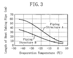
- FIG 3 is a graph showing the relation between the evaporation temperature in the chilling heat exchangers (16, 17) and the length of the heat taking pipe (90) with which the connecting part (25b) of the suction pressure sensor (25) reaches 10°C.
- "Piping Structure A” denotes a piping structure in which the heat taking pipe (90) and the discharge pipe (64) of the compressor (11) are not joined through the heat transfer member (91)
- "Piping Structure B” denotes a piping structure in which the heat taking pipe (90) and the discharge pipe (64) are joined through the heat transfer member (91) .
- FIG. 3 shows that, for Piping Structure A, the length of the heat taking pipe (90) with which the temperature of the connecting part (25b) of the suction pressure sensor (25) reaches 10°C needs to be increased with decreasing evaporation temperature in the chilling heat exchangers (16, 17) , such as 20cm at an evaporation temperature of -10°C, 48cm at - 30°C and 57cm at -40°C.
- the reason for this is as follows: As the evaporation temperature in the chilling heat exchangers (16, 17) decreases, the temperature of refrigerant flowing through the suction pipe (61) decreases.
- the cold heat of the refrigerant needs to be less likely to be transmitted to the connecting part (25b) of the suction pressure sensor (25) and the amount of heat taken from the ambient air by the heat taking pipe (90) needs to be increased by increasing the area of the heat taking pipe (90) .
- Figure 3 also shows that, for Piping Structure B, the length of the heat taking pipe (90) with which the temperature of the connecting part (25b) of the suction pressure sensor (25) reaches 10°C needs to be increased with decreasing evaporation temperature in the chilling heat exchangers (16, 17) , like Piping Structure A, but can be smaller than that in Piping Structure A at the same evaporation temperature, such as 10cm at an evaporation temperature of -10°C, 25cm at -30°C and 32cm at -40°C.
- the reason for this is that because the heat taking pipe (90) can take heat through the heat transfer member (91) from the high-temperature discharge pipe (64) of the compressor (11) , the heat taking pipe (90) can surely take a large amount of heat as compared with the case of taking heat only from the ambient air.
- the temperature of the connecting part (25b) of the suction pressure sensor (25) at least above 0°C is sufficient in order to avoid freezing of the connecting part (25b)
- examination in this experiment has been made of the length of the heat taking pipe (90) with which the temperature of the connecting part (25b) reaches 10°C.
- the reason for this is that when the length of the heat taking pipe (90) is set at a length with which the temperature of the connecting part (25b) becomes a predetermined temperature higher than 0°C, the temperature of the connecting part (25b) can be surely higher than 0°C even if the evaporation temperature in the chilling heat exchangers (16, 17) temporarily decreases owing to such as a variation in cooling load.
- the minimum length of the heat taking pipe (90) was set to a length shown in Figure 3 .
- the heat taking pipe (90) of Piping structure B needs to have a length of 10cm or more. Therefore, the heat taking pipe (90) was formed with a length of 20cm as a given length of 10cm or more.
- the four-way selector valve (12) of the outdoor circuit (20) is set to the first position and the outdoor expansion valve (45) is fully opened.
- the compressor (11) is driven and the openings of the chilling expansion valves (15a, 15b) and the branch expansion valve (46) are appropriately regulated, whereby refrigerant circulates in a direction showing in the solid arrows in Figure 4 .
- the set temperature of the cooling room during the cooling operation is 2°C, for example.
- the refrigerant discharged from the compressor (11) flows through the discharge pipe (64) and then through the four-way selector valve (12) and is then sent to the outdoor heat exchanger (13) .
- the outdoor heat exchanger (13) the refrigerant releases heat to the outside air to condense.
- the refrigerant condensed in the outdoor heat exchanger (13) flows through the first liquid pipe (81) , passes through the receiver (14) , flows into the second liquid pipe (82) and then flows through the first channel (50a) of the refrigerant heat exchanger (50) .
- the liquid refrigerant flowing through the first channel (50a) exchanges heat with the branched refrigerant flowing through the second channel (50b) to reduce its temperature to 15°C, for example, and then flows through the third liquid pipe (83) , then through the liquid-side shut-off valve (53) , then through the liquid-side connection pipe (21) and then into the in-chiller circuit (30) .
- the branched liquid refrigerant in the second channel (50b) evaporates and is then injected through the injection pipe (85) into the suction pipe (61) of the compressor (11) .
- liquid refrigerant at 15°C is distributed to the liquid-side branch pipes ( 21a, 21b) and flows through the drain pan heaters (26, 27) to prevent frosting of the drain pans.
- each of the drain pan heaters (26, 27) is reduced in pressure during passage through the associated chilling expansion valve (15a, 15b) to expand and is then introduced into the associated chilling heat exchanger (16, 17).
- refrigerant takes heat from the air in the cooling room to evaporate at an evaporation temperature of -10°C, for example.
- the air cooled by the chilling heat exchangers (16, 17) is supplied to the cooling room, whereby the temperature in the cooling room is kept at a set temperature of 2°C.
- the flows of refrigerant having flowed through the chilling heat exchangers (16, 17) pass through the respective gas-side branch pipes (22a, 22b) and are then combined together at the gas-side connection pipe (22) . Thereafter, the gas refrigerant flows through the gas-side connection pipe (22) , then flows through the four-way selector valve (12) and then through the suction pipe (61) , is then sucked into the compressor (11) and then compressed therein.
- the refrigeration system (1) is configured to temporarily stop the cooling operation and perform a defrosting operation.
- the behavior of the refrigeration system (1) during the defrosting operation is not given.
- the four-way selector valve (12) is set to the second position, the chilling expansion valves (15a, 15b) are fully opened, the branch expansion vale (46) is fully closed and the outdoor expansion valve (45) is appropriately controlled, whereby the refrigeration system (1) performs reverse cycle defrosting in which refrigerant circulates in the reverse direction to the direction during the cooling operation.
- gas refrigerant discharged from the compressor (11) flows through the chilling heat exchangers (16, 17) and the drain pan heaters (26, 27) to release heat to frost deposited on the chilling heat exchangers (16, 17) and the drain pans to condense into liquid form and then flows through the fourth liquid pipe (88) of the outdoor circuit (20) .
- the refrigerant flows through the liquid-side connection pipe (21) , is introduced into the outdoor circuit (20) , and then flows through the fourth liquid pipe (88) , then through the receiver (14) and then through the first channel (50a) of the refrigerant heat exchanger (50) .
- the refrigerant is expanded by the outdoor expansion valve (45) during passage through the fifth liquid pipe (89) , then condensed by the outdoor heat exchanger (13) and then sucked into the compressor (11) .
- the heat taking pipe (90) can make it difficult to transmit the cold heat of refrigerant flowing through the suction pipe (61) to the connecting part (25b) of the suction pressure sensor (25) and can take heat from the ambient air and the discharge pipe (64) .
- the connecting part (25b) of the suction pressure sensor (25) can have a higher temperature than 0°C even if refrigerant at - 10°C evaporated in the chilling heat exchangers (16, 17) flows through the suction pipe (61) .
- the connecting part (25b) of the suction pressure sensor (25) can be prevented from breakage due to freezing, which enhances the reliability of the suction pressure sensor (25) .
- the suction pressure sensor (25) can be prevented from breakage without silicone filling or brazing, the workability of mounting and replacement of the suction pressure sensor (25) can be enhanced as compared with conventional measures for preventing its breakage.
- the heat taking pipe (90) takes heat from the discharge pipe (64) of the refrigerant circuit (10) through the heat transfer member (91) , the amount of heat taken by the heat taking pipe (90) can be increased.
- the connecting part (25b) of the suction pressure sensor (25) can have a higher temperature than 0°C.
- the heat taking pipe (90) can take heat from the discharge pipe (64) of the compression mechanism (11) through the heat transfer member (91) , the amount of heat taken by the heat taking pipe (90) can surely be increased because the discharge pipe (64) of the compression mechanism (11) has a high temperature.
- the connecting part (25b) of the suction pressure sensor (25) can surely reach a higher temperature than 0°C.
- the above embodiment of the present invention may have the following configurations.
- the heat taking pipe (90) is formed with a length of 20cm and joined to the discharge pipe (64) by the heat transfer member (91) , the prevention of freezing may be implemented simply by forming the heat taking pipe (90) with a predetermined length without providing the heat transfer member (91) .
- the connecting part (25b) of the suction pressure sensor (25) can have a temperature of 10°C or higher.
- the connecting part (25b) can surely have a higher temperature than 0°C and can be prevented from breakage due to freezing, without joining the heat taking pipe (90) to the discharge pipe (64).
- the heat taking pipe (90) will do well if it is formed with a length with which the temperature of the connecting part (25b) of the suction pressure sensor (25) reaches a higher temperature than the suction pipe (61) owing to the ambient temperature. Furthermore, the minimum length of the heat taking pipe (90) is set to a predetermined length increasing as the evaporation temperature in the evaporators (16, 17) decreases.
- the heat taking pipe (90) may be disposed anywhere.
- the heat taking pipe (90) is disposed near the discharge pipe (64) , heat from the high-temperature discharge pipe (64) can be transmitted to the heat taking pipe (90) by air and the amount of heat taken by the heat taking pipe (90) becomes larger.
- the lengths of the heat taking pipe (90) shown in Figure 3 are illustrative only.
- the length of the heat taking pipe (90) is preferably selected as appropriate according such as to the temperature conditions of the surrounding area of the heat taking pipe (90) , the thermal conductivity of the heat transfer member (91) or the temperature of the discharge pipe (64) of the compressor (11) . If the variation in the cooling load of the refrigeration system (1) is small and the evaporation temperature in the evaporators (16, 17) is constant, the length of the heat taking pipe (90) may be set to a length with which the temperature of the connecting part (25b) of the suction pressure sensor (25) becomes 1°C, for example.
- the refrigeration system (1) of the above embodiment operates in a refrigeration cycle in which refrigerant is compressed in a single stage
- the refrigeration system may further include a freezing heat exchanger for freezing stored goods in the cooling room to operate in a refrigeration cycle in which refrigerant is compressed in two stages.
- the temperature of refrigerant flowing through the suction pipe of the low-pressure stage compressor is very low. Therefore, a pressure sensor for measuring the pressure of the low-temperature refrigerant may be mounted through a heat taking pipe to the suction pipe.
- the heat taking pipe may be joined through a heat transfer member to the high-pressure side pipe of the refrigerant circuit or the discharge pipe through which refrigerant discharged from the low-pressure stage compressor flows.
- the suction pressure sensors for the suction pipes of both the compressors may be connected to each other through a heat taking pipe.
- the heat taking pipe (90) is joined to the discharge pipe (64) of the compressor, it may be joined to any other high-pressure side pipe of the refrigerant circuit (10).
- a high-pressure side pipe include the first to third liquid pipes (81, 82, 83).
- the compression mechanism (11) is composed of a single compressor (11)
- the compression mechanism (11) may be composed of a plurality of compressors connected in parallel to each other.
- the present invention is useful for a refrigeration system including a suction pressure sensor for measuring the suction pressure of a compression mechanism.
Landscapes
- Engineering & Computer Science (AREA)
- Physics & Mathematics (AREA)
- Mechanical Engineering (AREA)
- Thermal Sciences (AREA)
- General Engineering & Computer Science (AREA)
- Other Air-Conditioning Systems (AREA)
- Air Conditioning Control Device (AREA)
Applications Claiming Priority (2)
| Application Number | Priority Date | Filing Date | Title |
|---|---|---|---|
| JP2006139040A JP4082434B2 (ja) | 2006-05-18 | 2006-05-18 | 冷凍装置 |
| PCT/JP2007/060151 WO2007135957A1 (fr) | 2006-05-18 | 2007-05-17 | Mécanisme de réfrigération |
Publications (1)
| Publication Number | Publication Date |
|---|---|
| EP2019273A1 true EP2019273A1 (fr) | 2009-01-28 |
Family
ID=38723269
Family Applications (1)
| Application Number | Title | Priority Date | Filing Date |
|---|---|---|---|
| EP07743586A Withdrawn EP2019273A1 (fr) | 2006-05-18 | 2007-05-17 | Mécanisme de réfrigération |
Country Status (7)
| Country | Link |
|---|---|
| US (1) | US20090188276A1 (fr) |
| EP (1) | EP2019273A1 (fr) |
| JP (1) | JP4082434B2 (fr) |
| KR (1) | KR20090013222A (fr) |
| CN (1) | CN101449118A (fr) |
| AU (1) | AU2007252631A1 (fr) |
| WO (1) | WO2007135957A1 (fr) |
Families Citing this family (6)
| Publication number | Priority date | Publication date | Assignee | Title |
|---|---|---|---|---|
| JP5585189B2 (ja) * | 2010-04-30 | 2014-09-10 | ダイキン工業株式会社 | 空気調和装置 |
| JP5821384B2 (ja) * | 2011-08-08 | 2015-11-24 | ダイキン工業株式会社 | センサの取付構造 |
| JP2014163548A (ja) * | 2013-02-22 | 2014-09-08 | Fujitsu General Ltd | 空気調和装置 |
| CN103759477B (zh) * | 2014-01-07 | 2016-06-29 | 广东美芝制冷设备有限公司 | 制冷循环装置 |
| JP6431776B2 (ja) * | 2015-01-19 | 2018-11-28 | 出光興産株式会社 | 潤滑油組成物 |
| CN111855735B (zh) * | 2020-08-06 | 2021-06-22 | 兰州理工大学 | 一种盐溶液盐胀及冻胀高效、精准测量装置 |
Family Cites Families (7)
| Publication number | Priority date | Publication date | Assignee | Title |
|---|---|---|---|---|
| JPS50148Y1 (fr) * | 1970-08-12 | 1975-01-06 | ||
| JPS5116317Y1 (fr) * | 1970-08-13 | 1976-04-28 | ||
| JPH0431689A (ja) * | 1990-05-24 | 1992-02-03 | Hitachi Ltd | スクロール圧縮機およびそれを用いた冷凍サイクル |
| JPH09329517A (ja) * | 1996-06-10 | 1997-12-22 | Fuji Koki:Kk | 圧力検出装置 |
| JP2002048665A (ja) * | 2000-07-31 | 2002-02-15 | Yamatake Corp | 圧力測定装置のスチームジャケット構造 |
| JP2004301456A (ja) * | 2003-03-31 | 2004-10-28 | Toyota Industries Corp | 冷凍サイクル装置及び冷凍サイクル装置用機器 |
| JP2004353996A (ja) | 2003-05-30 | 2004-12-16 | Daikin Ind Ltd | 冷凍装置 |
-
2006
- 2006-05-18 JP JP2006139040A patent/JP4082434B2/ja not_active Expired - Fee Related
-
2007
- 2007-05-17 KR KR1020087029682A patent/KR20090013222A/ko not_active Ceased
- 2007-05-17 CN CNA200780018084XA patent/CN101449118A/zh active Pending
- 2007-05-17 US US12/301,214 patent/US20090188276A1/en not_active Abandoned
- 2007-05-17 EP EP07743586A patent/EP2019273A1/fr not_active Withdrawn
- 2007-05-17 WO PCT/JP2007/060151 patent/WO2007135957A1/fr not_active Ceased
- 2007-05-17 AU AU2007252631A patent/AU2007252631A1/en not_active Abandoned
Non-Patent Citations (1)
| Title |
|---|
| See references of WO2007135957A1 * |
Also Published As
| Publication number | Publication date |
|---|---|
| JP2007309586A (ja) | 2007-11-29 |
| JP4082434B2 (ja) | 2008-04-30 |
| WO2007135957A1 (fr) | 2007-11-29 |
| US20090188276A1 (en) | 2009-07-30 |
| KR20090013222A (ko) | 2009-02-04 |
| AU2007252631A1 (en) | 2007-11-29 |
| CN101449118A (zh) | 2009-06-03 |
Similar Documents
| Publication | Publication Date | Title |
|---|---|---|
| JP3775358B2 (ja) | 冷凍装置 | |
| EP2320159A1 (fr) | Dispositif de réfrigération | |
| JPWO2018047416A1 (ja) | 空気調和装置 | |
| EP2023061A1 (fr) | Dispositif frigorifique | |
| US9719708B2 (en) | Air-conditioning apparatus with simultaneous heating and cooling operation | |
| EP2019273A1 (fr) | Mécanisme de réfrigération | |
| EP2837901A1 (fr) | Système de refroidissement et son procédé de commande | |
| EP1118823B1 (fr) | Dispositif de refrigeration a deux refrigerants | |
| US12038213B2 (en) | Refrigeration cycle apparatus | |
| EP2257749B1 (fr) | Système de réfrigération et son procédé d'exploitation | |
| EP3483523A1 (fr) | Appareil de cycle de réfrigération et appareil de climatisation équipé de celui-ci | |
| CN101344340B (zh) | 空调机 | |
| EP2314954B1 (fr) | Réfrigérateur | |
| US20090229301A1 (en) | Refrigeration system | |
| CN100451485C (zh) | 冷冻装置 | |
| CN115143555B (zh) | 空调系统 | |
| US20090077985A1 (en) | Refrigerating Apparatus | |
| EP3719408B1 (fr) | Climatiseur | |
| EP3480533B1 (fr) | Dispositif de réfrigération | |
| AU2005303098A1 (en) | Refrigeration system | |
| JP6157182B2 (ja) | 冷凍装置 | |
| EP4624832A1 (fr) | Unité de source de chaleur et dispositif de réfrigération | |
| US20250164168A1 (en) | Heat source unit and refrigeration apparatus | |
| JP2001183037A (ja) | 冷凍装置 | |
| JP2008032337A (ja) | 冷凍装置 |
Legal Events
| Date | Code | Title | Description |
|---|---|---|---|
| PUAI | Public reference made under article 153(3) epc to a published international application that has entered the european phase |
Free format text: ORIGINAL CODE: 0009012 |
|
| 17P | Request for examination filed |
Effective date: 20081120 |
|
| AK | Designated contracting states |
Kind code of ref document: A1 Designated state(s): AT BE BG CH CY CZ DE DK EE ES FI FR GB GR HU IE IS IT LI LT LU LV MC MT NL PL PT RO SE SI SK TR |
|
| AX | Request for extension of the european patent |
Extension state: AL BA HR MK RS |
|
| STAA | Information on the status of an ep patent application or granted ep patent |
Free format text: STATUS: THE APPLICATION HAS BEEN WITHDRAWN |
|
| 18W | Application withdrawn |
Effective date: 20101216 |