EP2019325A2 - Signalverarbeitungssystem für Doppler-Impulsradar - Google Patents
Signalverarbeitungssystem für Doppler-Impulsradar Download PDFInfo
- Publication number
- EP2019325A2 EP2019325A2 EP08160756A EP08160756A EP2019325A2 EP 2019325 A2 EP2019325 A2 EP 2019325A2 EP 08160756 A EP08160756 A EP 08160756A EP 08160756 A EP08160756 A EP 08160756A EP 2019325 A2 EP2019325 A2 EP 2019325A2
- Authority
- EP
- European Patent Office
- Prior art keywords
- doppler
- thresholding
- range
- processing system
- signal processing
- Prior art date
- Legal status (The legal status is an assumption and is not a legal conclusion. Google has not performed a legal analysis and makes no representation as to the accuracy of the status listed.)
- Withdrawn
Links
Images


Classifications
-
- G—PHYSICS
- G01—MEASURING; TESTING
- G01S—RADIO DIRECTION-FINDING; RADIO NAVIGATION; DETERMINING DISTANCE OR VELOCITY BY USE OF RADIO WAVES; LOCATING OR PRESENCE-DETECTING BY USE OF THE REFLECTION OR RERADIATION OF RADIO WAVES; ANALOGOUS ARRANGEMENTS USING OTHER WAVES
- G01S7/00—Details of systems according to groups G01S13/00, G01S15/00, G01S17/00
- G01S7/02—Details of systems according to groups G01S13/00, G01S15/00, G01S17/00 of systems according to group G01S13/00
- G01S7/28—Details of pulse systems
- G01S7/285—Receivers
- G01S7/292—Extracting wanted echo-signals
- G01S7/2923—Extracting wanted echo-signals based on data belonging to a number of consecutive radar periods
- G01S7/2927—Extracting wanted echo-signals based on data belonging to a number of consecutive radar periods by deriving and controlling a threshold value
-
- G—PHYSICS
- G01—MEASURING; TESTING
- G01S—RADIO DIRECTION-FINDING; RADIO NAVIGATION; DETERMINING DISTANCE OR VELOCITY BY USE OF RADIO WAVES; LOCATING OR PRESENCE-DETECTING BY USE OF THE REFLECTION OR RERADIATION OF RADIO WAVES; ANALOGOUS ARRANGEMENTS USING OTHER WAVES
- G01S13/00—Systems using the reflection or reradiation of radio waves, e.g. radar systems; Analogous systems using reflection or reradiation of waves whose nature or wavelength is irrelevant or unspecified
- G01S13/02—Systems using reflection of radio waves, e.g. primary radar systems; Analogous systems
- G01S13/50—Systems of measurement based on relative movement of target
- G01S13/52—Discriminating between fixed and moving objects or between objects moving at different speeds
- G01S13/522—Discriminating between fixed and moving objects or between objects moving at different speeds using transmissions of interrupted pulse modulated waves
- G01S13/524—Discriminating between fixed and moving objects or between objects moving at different speeds using transmissions of interrupted pulse modulated waves based upon the phase or frequency shift resulting from movement of objects, with reference to the transmitted signals, e.g. coherent MTi
- G01S13/5246—Discriminating between fixed and moving objects or between objects moving at different speeds using transmissions of interrupted pulse modulated waves based upon the phase or frequency shift resulting from movement of objects, with reference to the transmitted signals, e.g. coherent MTi post processors for coherent MTI discriminators, e.g. residue cancellers, CFAR after Doppler filters
Definitions
- This invention relates to a signal processing system for use in pulse-Doppler radar, and in particular to a constant false alarm rate system for reducing the influence of clutter.
- pulse-Doppler radars transmit a series of pulses which are coherent from one to the next.
- the returns from each pulse are digitised to give one sample in each range cell and for each pulse.
- the set of pulses corresponding to the returns from a signal range cell over the different transmitted pulses are Fourier transformed so that a series of Doppler bins is produced for each range cell, the signal in a particular range-Doppler bin corresponding to a signal from a target, or a portion of the image scene, at that range and moving with a particular speed.
- the purpose of this processing is to separate moving targets from slow-moving clutter.
- the first stage of the detection process is to calculate a local average signal level, which may be averaged over adjacent ranges but within the same Doppler frequency bin, or it may be averaged over adjacent Doppler frequency bins. If the ratio between the signal level in a particular range and Doppler bin and the average is greater than a predetermined threshold, then a target is declared and this will lead to a blip being formed on a display.
- This process of thresholding is known as pulse-Doppler constant false alarm rate processing, or PD-CFAR processing.
- PD-CFAR processing pulse-Doppler constant false alarm rate processing
- the purpose of the present invention is to improve the signal processing in pulse Doppler radar systems in order to enhance sensitivity and eliminate more clutter.
- the invention provides a signal processing system for use in pulse-Doppler radar, arranged to receive frequency domain signals for each of a plurality of Doppler bins for each range cell, comprising a data processor arranged successively to threshold each Doppler bin signal under test relative to a local average of signals formed over plural Doppler bins and/or plural ranges adjacent to the Doppler bin under test, using a variable thresholding factor, and using the thresholding result as an indication of the presence of an object of interest; the data processor using a pulse-Doppler constant false alarm rate control process to set and reset the variable thresholding factor using closed loop feedback by counting the indications of presence and incrementing or decrementing the variable thresholding factor for each thresholding result by comparing the frequency of these counts with a predetermined probability of false alarms; whereby the constant false alarm rate thresholding is a function of the range and the Doppler frequency of the range-Doppler bin signal under test.
- the system is arranged to receive and separately to process the frequency domain signals for each angular range in azimuth of a multiplicity of angular ranges, whereby the constant false alarm rate thresholding is also a function of azimuthal angle.
- An exciter generates a continuous, highly stable, low power signal of a frequency which is selectable over a wide range by an operator, and of the desired phase, for the transmitter; the exciter also generates, precisely offset from the transmitter signal, a local oscillator signal L01 and a reference frequency signal Ref. for the receiver.
- Both the transmitter and the receiver are connected by way of a duplexer to a planar array antenna whose orientation and configuration is controlled by a drive mechanism receiving control signals from a radar data processor.
- the radar data processor receives control signals from operator controls, and also receives output signals from a signal processor shown in more detail in Figure 3 .
- the radar data processor has outputs to the exciter, transmitter, receiver and signal processor.
- the signal processor provides an output to a display adjacent the operator.
- the transmitter is typically a high power amplifier of the type known as a gridded travelling-wave tube.
- the transmitter is keyed on and off to cut coherent pulses from the exciter's signal and it amplifies these pulses to the desired power level for transmission.
- the width and pulse repetition frequency of the transmitted pulses are capable of modification under the control of the radar data processor.
- the exciter's low power signal may be modified by the radar data processor, so as to change or modulate the frequency, phase and power level of the high power pulses, or to code them for pulse compression.
- the receiver receives a signal S from the duplexer through a receiver protection device, and, as shown in Figure 2 , it comprises a low noise preamplifier upstream of a mixer.
- the mixer receives the local oscillator signal at frequency f LO1 to produce an intermediate frequency signal at f IF1 which is fed to an IF amplifier.
- a synchronous video detector receives the reference signal Ref. from the exciter and the output of the second IF amplifier, to generate video frequency signals I,Q in phase quadrature which are fed to an analogue to digital converter. This beats the Doppler shifted received return signals against the reference signal and produces the bipolar video outputs whose amplitudes are sampled at intervals of the order of a pulse width.
- the output of the analogue to digital converter is numerical and is supplied to the signal processor which is shown in greater detail in Figure 3 .
- the signal processor of Figure 3 sorts the incoming digital signals into range bins in accordance with their time of arrival, storing the numbers in range bins; it also filters out the bulk of unwanted ground clutter or sea clutter on the basis of Doppler frequency.
- a set of Doppler filter banks sorts signals into each range increment by their Doppler frequency.
- the processor integrates the energy of successive echoes from the same target, i.e. echoes which have the same Doppler frequency, to reduce still further the background of noise and clutter. This is performed by a threshold detector which operates on a variable threshold setting using a closed loop feedback arrangement as shown.
- the system processor temporarily stores the positions of the targets in memory.
- the scan converter receives a signal from the data processor indicating the current angle in azimuth of the antenna, so that the display represents moving targets in a two-dimensional scene taking account of both range and azimuthal angle.
- a block for executing burst to burst correlation is a block for executing burst to burst correlation. This reduces the false alarm rate. It allows the CFAR to run at a false alarm rate high enough for the false alarm rate to be estimated with adequate accuracy and relatively fast, whilst allowing the displayed false alarm rate to be much lower, i.e. low enough to be acceptable to the operator.
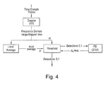
- a Doppler fast Fourier transform unit Doppler FFT receives digital signals representing time domain pulses, and converts them into the frequency domain so that they represent range-Doppler bins, i.e. Doppler frequency bins for each of several ranges.
- Each range-Doppler bin signal x i is fed to a local average processor and also to a thresholding processor for pulse Doppler constant false alarm rate thresholding, the output of which thresholding is a binary indicator indicative of the presence of or absence of an object of interest, i.e. a target.
- a local average processor calculates a local average signal level which, in this example, is taken from the same Doppler bin but over adjacent ranges.
- the local average z i is fed to the threshold processor which receives a threshold multiplier ALPHA from the pulse Doppler constant false alarm rate processor or PD CFAR.
- the threshold processor compares the local average z i with the Doppler bin signal x i under test in accordance with the current variable value of the threshold multiplier ALPHA, and outputs the binary result 0 or 1 dependent upon the result of the comparison.
- the threshold processor may for example multiply x i by ALPHA and compare it with z i .
- the PD CFAR processor receives the binary output of the threshold processor and stores a count of these detection values.
- the PD CFAR also receives a signal representing the required probability P fa of pulse alarms, which could typically be of the order of 10 -6 .
- a thresholding processor in the PD CFAR receives the count and the required P fa and determines whether the threshold multiplier ALPHA should be incremented or decremented in order to converge to the required P fa ; the PD CFAR then applies the appropriate predetermined amount of increment or decrement in accordance with the thresholding result, and feeds back the threshold multiplier ALPHA to the threshold processor. In this way, the sensitivity of the PD CFAR system is adjusted iteratively to converge onto a required probability P fa .
- the PD CFAR operates on individual range-Doppler bins. This leads to a significant improvement over previous PD CFAR arrangements.
- range-Doppler bins are processed in discrete angular ranges of azimuth. These azimuthal ranges or angular cells are preferably of equal size, and for example there may be twelve angular cells each of 30°. In a typical pulse Doppler radar, there may for example be of the order of ten or twenty Doppler cells.
- Figure 5 illustrates actual clutter power in terms of signal to noise ratio in dB, for each different Doppler frequency bin, in a typical scene at sea, averaged over all the range bins.
- Figure 6 illustrates the way in which the PD CFAR system sets the threshold multiplier ALPHA, for each of the different Doppler frequency bins.
- the graph shown in Figure 6 corresponds to just one angular azimuthal range, i.e. one angular cell, as the radar scans around. The graph varies significantly from angular cell to cell.
- the tails of the Doppler frequency, i.e. the lowest and the highest Doppler frequencies require the highest threshold multipliers, as shown by the two peaks in Figure 6 . This markedly asymmetric distribution will occupy different Doppler bins corresponding to different resolved clutter velocities when the sea is observed from different directions as the radar scans.
- the radar preferably transmits a number of separate bursts of pulses, each at a different pulse repetition frequency and, incidentally, at a different carrier frequency.
- This difference in pulse repetition frequencies allows the range ambiguities to be resolved; by requiring typically three detections in the same unambiguous range cell over the typically six pulse repetition frequencies, this also greatly reduces the pulse alarm rate.
- the detections at the individual pulse repetition frequencies, which are counted by the PD CFAR system are much more frequent than the displayed false alarms. This in turn allows a reasonable number, for example ten, of false alarms to be counted in each angular Doppler cell over say ten scans of the radar, whilst having a much lower false alarm rate shown on the display.
- Ten false alarms is about the minimum necessary to provide a meaningful estimate of the false alarm rate.
- a low pass filter, executed in software, in the feedback loop in the PD CFAR performs this averaging. For a slow-moving platform such as a helicopter, this is sufficiently fast to allow the system to adapt as the radar platform manoeuvres.
- Another preferred feature of the signal processing system is the summation of false alarms in a particular Doppler bin over all the pulse repetition frequencies, even though that bin corresponds to a significantly different velocity range for each pulse repetition frequency. It has been found in practice that the advantage of having more data to obtain a better estimate of the false alarm rate more quickly, more than compensates for the reduced accuracy of that estimate due to the overlapping of the Doppler bins.
- the invention may be implemented in many different ways from that shown in the embodiment of Figure 4 . It may be implemented predominantly in computer software.
- the output may be displayed in real time or it may be stored and subsequently processed, depending upon the particular requirements.
- the PD CFAR system may respond to the different values of the angular cells and to the different ways in which local averaging is undertaken, either by operator input or by automatic response to other parts of the signal processing system or of the overall pulse Doppler radar apparatus.
- the computation performed by the threshold processor could be done in many different ways, not necessarily involving multiplication by a threshold multiplier, provided that there is some form of variable threshold which is adjusted iteratively in the feedback loop.
Landscapes
- Engineering & Computer Science (AREA)
- Radar, Positioning & Navigation (AREA)
- Remote Sensing (AREA)
- Computer Networks & Wireless Communication (AREA)
- Physics & Mathematics (AREA)
- General Physics & Mathematics (AREA)
- Radar Systems Or Details Thereof (AREA)
Applications Claiming Priority (1)
| Application Number | Priority Date | Filing Date | Title |
|---|---|---|---|
| GB0714347A GB2451242A (en) | 2007-07-23 | 2007-07-23 | Signal processing system for pulse doppler radar |
Publications (2)
| Publication Number | Publication Date |
|---|---|
| EP2019325A2 true EP2019325A2 (de) | 2009-01-28 |
| EP2019325A3 EP2019325A3 (de) | 2009-09-16 |
Family
ID=38925733
Family Applications (1)
| Application Number | Title | Priority Date | Filing Date |
|---|---|---|---|
| EP08160756A Withdrawn EP2019325A3 (de) | 2007-07-23 | 2008-07-18 | Signalverarbeitungssystem für Doppler-Impulsradar |
Country Status (3)
| Country | Link |
|---|---|
| US (1) | US7737881B2 (de) |
| EP (1) | EP2019325A3 (de) |
| GB (1) | GB2451242A (de) |
Cited By (1)
| Publication number | Priority date | Publication date | Assignee | Title |
|---|---|---|---|---|
| CN101887115A (zh) * | 2010-06-30 | 2010-11-17 | 中国电子科技集团公司第三十八研究所 | 脉冲检测门限计算模块 |
Families Citing this family (10)
| Publication number | Priority date | Publication date | Assignee | Title |
|---|---|---|---|---|
| JP5697910B2 (ja) * | 2010-07-06 | 2015-04-08 | 古野電気株式会社 | 閾値設定方法、物標探知方法、閾値設定装置、物標探知装置、閾値設定プログラム、および物標探知プログラム |
| US8344944B2 (en) * | 2010-08-02 | 2013-01-01 | Raytheon Company | Method and system for continuous wave interference suppression in pulsed signal processing |
| EP2636283B1 (de) | 2010-11-02 | 2018-08-29 | Philips Lighting Holding B.V. | Beleuchtungssystem mit radardetektion |
| JP5821419B2 (ja) * | 2011-08-30 | 2015-11-24 | 富士通株式会社 | 移動物体検出装置、移動物体検出方法及び移動物体検出用コンピュータプログラム |
| CN102819010B (zh) * | 2012-08-14 | 2014-01-29 | 成都西科微波通讯有限公司 | 一种改进的二维恒虚警方法 |
| US9594159B2 (en) * | 2013-07-15 | 2017-03-14 | Texas Instruments Incorporated | 2-D object detection in radar applications |
| JP6384018B2 (ja) * | 2014-03-25 | 2018-09-05 | 日本無線株式会社 | 車載用レーダ装置 |
| US9823110B2 (en) * | 2015-07-27 | 2017-11-21 | Finetek Co., Ltd. | Radar liquid level measuring apparatus and radar liquid level measuring method |
| US11693091B2 (en) * | 2020-12-28 | 2023-07-04 | GM Global Technology Operations LLC | Radar detection and parameter estimation of accelerating objects |
| US20230236045A1 (en) * | 2022-01-25 | 2023-07-27 | Network Integrity Systems, Inc. | Method of analyzing a monitoring signal from a sensing system to determine an alarm condition |
Family Cites Families (15)
| Publication number | Priority date | Publication date | Assignee | Title |
|---|---|---|---|---|
| US3877010A (en) * | 1967-10-26 | 1975-04-08 | Hughes Aircraft Co | Adaptable moving target processor |
| US3631486A (en) * | 1969-06-24 | 1971-12-28 | Westinghouse Electric Corp | Processing method and commutation system for pulse doppler radar |
| US4249177A (en) * | 1979-05-03 | 1981-02-03 | The United States Of America As Represented By The Secretary Of The Air Force | Target discrimination apparatus |
| IT1189312B (it) * | 1982-07-08 | 1988-02-04 | Selenia Ind Elettroniche | Dispositivo per la cancellazione post-detezione di falsi echi radar |
| US4970660A (en) * | 1985-07-05 | 1990-11-13 | Motorola, Inc. | Accumulated statistics constant false alarm rate method and device |
| DE3689037D1 (de) * | 1985-12-23 | 1993-10-21 | Nec Corp | Radarsystem. |
| US4963888A (en) * | 1988-11-03 | 1990-10-16 | Westinghouse Electric Corp. | Single-scan editor of bird echoes |
| US5038145A (en) * | 1989-11-20 | 1991-08-06 | Westinghouse Electric Corp. | Constant false alarm rate with low probability of false alarms |
| JP2967672B2 (ja) * | 1993-07-28 | 1999-10-25 | 三菱電機株式会社 | レーダ信号処理装置 |
| US5416488A (en) * | 1993-12-27 | 1995-05-16 | Motorola, Inc. | Radar return signal processing method |
| US5499030A (en) * | 1994-03-18 | 1996-03-12 | The United States Of America As Represented By The Secretary Of The Air Force | Expert system constant false alarm rate (CFAR) processor |
| US5485157A (en) * | 1994-10-11 | 1996-01-16 | Long; Maurice W. | Doppler radar detection system |
| GB9500878D0 (en) * | 1995-01-17 | 1995-03-15 | Thorn Emi Electronics Ltd | Method and apparatus for estimating the detection range of a radar |
| BR0308287A (pt) * | 2002-03-13 | 2005-01-11 | Raytheon Canada Ltd | Sistema e método de detecção adaptáveis |
| US7212150B2 (en) * | 2005-04-21 | 2007-05-01 | The United States Of America As Represented By The Secretary Of The Navy | Doppler-sensitive adaptive coherence estimate detector methods |
-
2007
- 2007-07-23 GB GB0714347A patent/GB2451242A/en not_active Withdrawn
-
2008
- 2008-07-18 EP EP08160756A patent/EP2019325A3/de not_active Withdrawn
- 2008-07-21 US US12/176,595 patent/US7737881B2/en not_active Expired - Fee Related
Cited By (1)
| Publication number | Priority date | Publication date | Assignee | Title |
|---|---|---|---|---|
| CN101887115A (zh) * | 2010-06-30 | 2010-11-17 | 中国电子科技集团公司第三十八研究所 | 脉冲检测门限计算模块 |
Also Published As
| Publication number | Publication date |
|---|---|
| GB0714347D0 (en) | 2008-01-02 |
| EP2019325A3 (de) | 2009-09-16 |
| GB2451242A (en) | 2009-01-28 |
| US20090027255A1 (en) | 2009-01-29 |
| US7737881B2 (en) | 2010-06-15 |
Similar Documents
| Publication | Publication Date | Title |
|---|---|---|
| US7737881B2 (en) | Signal processing system for pulse-doppler radar | |
| US11592520B2 (en) | FMCW radar with interfering signal suppression in the time domain | |
| US5784026A (en) | Radar detection of accelerating airborne targets | |
| US7903024B2 (en) | Adaptive moving target indicator (MTI) clutter rejection filter for radar systems | |
| CN103210319B (zh) | 雷达系统 | |
| EP2097769B1 (de) | System und verfahren zum verringern der auswirkung eines radarstörungssignals | |
| EP1672379B1 (de) | System und Verfahren zur Verminderung eines Radarstörsignals | |
| US6809682B1 (en) | Method and device for the detection and track of targets in high clutter | |
| US9140783B2 (en) | Radar device | |
| EP1980873B1 (de) | Verlaufs- oder bildbasierte Verfahren zur Höhenbestimmung in einem Radarhöhenmesser | |
| EP0557945B1 (de) | Entfernungsmessung, Detektion und Auflösung in einem Radarsystem mit Verwendung von frequenzmodulierten Wellenformen mit mehrfachen Steilheiten | |
| US5748143A (en) | Adaptive post-doppler sequential beam processor | |
| EP0777132B1 (de) | Radarsystem | |
| US5309160A (en) | Radar system and method having variable tracking range | |
| EP2363728A1 (de) | Verschachtelte strahlenkohärente Radarvorrichtung und Verarbeitungsverfahren | |
| NO342921B1 (no) | Radaranordning | |
| US4633254A (en) | Circuit arrangement for post-detection suppression of spurious radar echoes | |
| CA2009601A1 (en) | Blind speed elimination for dual displaced phase center antenna radar processor mounted on a moving platform | |
| US4630052A (en) | Suppressor of second-time-around clutter echoes for MTI pulse radar provided with power oscillator | |
| US4670753A (en) | Method and apparatus for minimum amplitude time history analysis | |
| EP4343368A1 (de) | Radarbasierte segmentierte präsenzerkennung | |
| US4688043A (en) | High resolution radar system | |
| GB2074807A (en) | M.T.I. radar processor | |
| KR20250005119A (ko) | 효율적인 레이더 전처리를 위한 방법 | |
| RU2316788C1 (ru) | Способ обнаружения групповой цели импульсно-доплеровской радиолокационной станцией |
Legal Events
| Date | Code | Title | Description |
|---|---|---|---|
| PUAI | Public reference made under article 153(3) epc to a published international application that has entered the european phase |
Free format text: ORIGINAL CODE: 0009012 |
|
| AK | Designated contracting states |
Kind code of ref document: A2 Designated state(s): AT BE BG CH CY CZ DE DK EE ES FI FR GB GR HR HU IE IS IT LI LT LU LV MC MT NL NO PL PT RO SE SI SK TR |
|
| AX | Request for extension of the european patent |
Extension state: AL BA MK RS |
|
| PUAL | Search report despatched |
Free format text: ORIGINAL CODE: 0009013 |
|
| AK | Designated contracting states |
Kind code of ref document: A3 Designated state(s): AT BE BG CH CY CZ DE DK EE ES FI FR GB GR HR HU IE IS IT LI LT LU LV MC MT NL NO PL PT RO SE SI SK TR |
|
| AX | Request for extension of the european patent |
Extension state: AL BA MK RS |
|
| 17P | Request for examination filed |
Effective date: 20091007 |
|
| 17Q | First examination report despatched |
Effective date: 20091102 |
|
| AKX | Designation fees paid |
Designated state(s): AT BE BG CH CY CZ DE DK EE ES FI FR GB GR HR HU IE IS IT LI LT LU LV MC MT NL NO PL PT RO SE SI SK TR |
|
| STAA | Information on the status of an ep patent application or granted ep patent |
Free format text: STATUS: THE APPLICATION IS DEEMED TO BE WITHDRAWN |
|
| 18D | Application deemed to be withdrawn |
Effective date: 20100513 |