EP2019335B1 - Lithografische Vorrichtung und Verfahren zur Entfernung oder Verhinderung von Verschmutzung - Google Patents
Lithografische Vorrichtung und Verfahren zur Entfernung oder Verhinderung von Verschmutzung Download PDFInfo
- Publication number
- EP2019335B1 EP2019335B1 EP08252507.2A EP08252507A EP2019335B1 EP 2019335 B1 EP2019335 B1 EP 2019335B1 EP 08252507 A EP08252507 A EP 08252507A EP 2019335 B1 EP2019335 B1 EP 2019335B1
- Authority
- EP
- European Patent Office
- Prior art keywords
- liquid
- cleaning
- immersion
- radiation
- substrate
- Prior art date
- Legal status (The legal status is an assumption and is not a legal conclusion. Google has not performed a legal analysis and makes no representation as to the accuracy of the status listed.)
- Not-in-force
Links
Images


Classifications
-
- G—PHYSICS
- G03—PHOTOGRAPHY; CINEMATOGRAPHY; ANALOGOUS TECHNIQUES USING WAVES OTHER THAN OPTICAL WAVES; ELECTROGRAPHY; HOLOGRAPHY
- G03F—PHOTOMECHANICAL PRODUCTION OF TEXTURED OR PATTERNED SURFACES, e.g. FOR PRINTING, FOR PROCESSING OF SEMICONDUCTOR DEVICES; MATERIALS THEREFOR; ORIGINALS THEREFOR; APPARATUS SPECIALLY ADAPTED THEREFOR
- G03F7/00—Photomechanical, e.g. photolithographic, production of textured or patterned surfaces, e.g. printing surfaces; Materials therefor, e.g. comprising photoresists; Apparatus specially adapted therefor
- G03F7/70—Microphotolithographic exposure; Apparatus therefor
- G03F7/70216—Mask projection systems
- G03F7/70341—Details of immersion lithography aspects, e.g. exposure media or control of immersion liquid supply
-
- G—PHYSICS
- G03—PHOTOGRAPHY; CINEMATOGRAPHY; ANALOGOUS TECHNIQUES USING WAVES OTHER THAN OPTICAL WAVES; ELECTROGRAPHY; HOLOGRAPHY
- G03F—PHOTOMECHANICAL PRODUCTION OF TEXTURED OR PATTERNED SURFACES, e.g. FOR PRINTING, FOR PROCESSING OF SEMICONDUCTOR DEVICES; MATERIALS THEREFOR; ORIGINALS THEREFOR; APPARATUS SPECIALLY ADAPTED THEREFOR
- G03F7/00—Photomechanical, e.g. photolithographic, production of textured or patterned surfaces, e.g. printing surfaces; Materials therefor, e.g. comprising photoresists; Apparatus specially adapted therefor
- G03F7/20—Exposure; Apparatus therefor
- G03F7/2041—Exposure; Apparatus therefor in the presence of a fluid, e.g. immersion; using fluid cooling means
-
- G—PHYSICS
- G03—PHOTOGRAPHY; CINEMATOGRAPHY; ANALOGOUS TECHNIQUES USING WAVES OTHER THAN OPTICAL WAVES; ELECTROGRAPHY; HOLOGRAPHY
- G03F—PHOTOMECHANICAL PRODUCTION OF TEXTURED OR PATTERNED SURFACES, e.g. FOR PRINTING, FOR PROCESSING OF SEMICONDUCTOR DEVICES; MATERIALS THEREFOR; ORIGINALS THEREFOR; APPARATUS SPECIALLY ADAPTED THEREFOR
- G03F7/00—Photomechanical, e.g. photolithographic, production of textured or patterned surfaces, e.g. printing surfaces; Materials therefor, e.g. comprising photoresists; Apparatus specially adapted therefor
- G03F7/70—Microphotolithographic exposure; Apparatus therefor
- G03F7/708—Construction of apparatus, e.g. environment aspects, hygiene aspects or materials
- G03F7/70908—Hygiene, e.g. preventing apparatus pollution, mitigating effect of pollution or removing pollutants from apparatus
- G03F7/70925—Cleaning, i.e. actively freeing apparatus from pollutants, e.g. using plasma cleaning
Definitions
- the present invention relates to a lithographic apparatus and a method for removing or preventing contamination in a lithographic apparatus.
- a lithographic apparatus is a machine that applies a desired pattern onto a substrate, usually onto a target portion of the substrate.
- a lithographic apparatus can be used, for example, in the manufacture of integrated circuits (ICs).
- a patterning device which is alternatively referred to as a mask or a reticle, may be used to generate a circuit pattern to be formed on an individual layer of the IC.
- This pattern can be transferred onto a target portion (e.g. comprising part of, one, or several dies) on a substrate (e.g. a silicon wafer). Transfer of the pattern is typically via imaging onto a layer of radiation-sensitive material (resist) provided on the substrate.
- resist radiation-sensitive material
- a single substrate will contain a network of adjacent target portions that are successively patterned.
- lithographic apparatus include so-called steppers, in which each target portion is irradiated by exposing an entire pattern onto the target portion at one time, and so-called scanners, in which each target portion is irradiated by scanning the pattern through a radiation beam in a given direction (the "scanning"-direction) while synchronously scanning the substrate parallel or anti-parallel to this direction. It is also possible to transfer the pattern from the patterning device to the substrate by imprinting the pattern onto the substrate.
- liquid supply system to provide liquid on only a localized area of the substrate and in between the final element of the projection system and the substrate using a liquid confinement system (the substrate generally has a larger surface area than the final element of the projection system).
- a liquid confinement system the substrate generally has a larger surface area than the final element of the projection system.
- liquid is supplied by at least one inlet IN onto the substrate, preferably along the direction of movement of the substrate relative to the final element, and is removed by at least one outlet OUT after having passed under the projection system.
- Figure 2 shows the arrangement schematically in which liquid is supplied via inlet IN and is taken up on the other side of the element by outlet OUT which is connected to a low pressure source.
- the liquid is supplied along the direction of movement of the substrate relative to the final element, though this does not need to be the case.
- Figure 3 Various orientations and numbers of in- and out-lets positioned around the final element are possible, one example is illustrated in Figure 3 in which four sets of an inlet with an outlet on either side are provided in a regular pattern around the final element.
- EP-A-1 783 822 describes an exposure device and a method for cleaning the exposure device.
- the device incorporates a reflecting member 700, the upper surface of which is capable of reflecting a light beam onto a lower surface of a nozzle member or the lower surface of an optical member, in order to provide cleaning of the lower surfaces of the nozzle member and optical member.
- a reflecting member 700 the upper surface of which is capable of reflecting a light beam onto a lower surface of a nozzle member or the lower surface of an optical member, in order to provide cleaning of the lower surfaces of the nozzle member and optical member.
- the effective intensity per unit area of the cleaning radiation is low and there is a need for an improved cleaning technique.
- US 2005185155 describes an exposure apparatus, a fluid that is present in the space between the projection optical system and a reticle, and an adding unit for adding an oxidative additive to the fluid.
- EP-A-1 793 276 describes a method for preventing or reducing contamination of a projection apparatus which involves rinsing at least part of an immersion space of the projection apparatus with a rinsing liquid.
- EP-A-1 777 589 describes a lithography apparatus having a cleaning module adapted to clean the apparatus.
- the cleaning module comprises one of an ultrasonic unit, a scrubber, a fluid jet, an electrostatic cleaner and combinations thereof.
- US 2007004182 describes an immersion lithography system wherein the immersion fluid holder includes a coating configured to reduce adhesion of contaminants which are present in the immersion fluid.
- An effective cleaning method can involve the use of an organic solvent or other highly oxidizing cleaning material such as ozone.
- a highly corrosive cleaning agent may cause a considerable risk of damage to component surfaces, and it may therefore be desirable to minimize or avoid their use entirely in order to limit the resulting damage.
- a cleaning material may leave a deposit on the surface to which it is exposed and the deposit may need to be removed before the apparatus can be used. Rinsing to remove such a deposit should be thorough and therefore takes time. This may be particularly difficult with an organic cleaning solvent which is not easily removed by rinsing with, for example, water.
- ozone may also cause particular difficulty, not least of which is the extremely hazardous nature of ozone which leads to safety concerns when handling the material. Removal of ozone after its use should also be thorough and adds to the cost and complication of the cleaning method.
- a commercially available ozonizer may be unsuitable since it produces hydrogen gas, which is dangerous. Further, many commercial processes produce too many impurities to be useful in the ultra-high purity environment which is needed.
- UV radiation is used to activate the ozone to more reactive hydroxyl radicals
- additional cleaning effect can be generated.
- the radicals are themselves very short-lived and are substantially only present within the spot of UV radiation.
- the use of multiple radiation sources or multiple mirrors to ensure that all parts of the apparatus are cleaned may be impractical.
- an immersion type lithographic apparatus comprising: a projection system (PL) for projecting a beam of radiation (B) onto a substrate (W); a substrate table (WT) for holding the substrate (W); an immersion system configured to at least partially fill an immersion space between the projection system (PL) and the substrate table (WT) with an immersion liquid; a liquid retrieval system for retrieving the immersion liquid from the immersion space; and a liquid supply system for providing a cleaning liquid to the immersion space, the cleaning liquid being contained in the immersion space and/or in the liquid supply system and consisting of ultra-pure water and (a) a mixture of hydrogen peroxide and ozone, or (b) hydrogen peroxide at a concentration of up to 10%, or (c) ozone at a concentration of up to 50 ppm, or (d) oxygen at concentration of up to 10 ppm, or (e) any combination selected from (a)-(d), wherein the substrate table (WT) comprises, on a surface facing the projection system
- the liquid supply system may be part of an immersion liquid supply system.
- the immersion liquid supply system is used to supply immersion fluid during immersion.
- the liquid supply system for providing cleaning liquid may be totally or partially separate from the immersion liquid supply system.
- a method for preventing or reducing contamination in an immersion type lithographic apparatus comprising a projection system (PL) for projecting a beam of radiation (B) onto a substrate (W), a substrate table (WT) for holding the substrate (W), an immersion system configured to at least partially fill an immersion space between the projection system (PL) and the substrate table (WT) with an immersion liquid, and a liquid retrieval system for retrieving the immersion liquid from the immersion space, the method comprising:
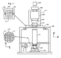
- Figure 1 schematically depicts a lithographic apparatus according to one embodiment of the invention.
- the apparatus comprises:
- the illumination system may include various types of optical components, such as refractive, reflective, magnetic, electromagnetic, electrostatic or other types of optical components, or any combination thereof, for directing, shaping, or controlling radiation.
- optical components such as refractive, reflective, magnetic, electromagnetic, electrostatic or other types of optical components, or any combination thereof, for directing, shaping, or controlling radiation.
- the patterning device support structure holds the patterning device in a manner that depends on the orientation of the patterning device, the design of the lithographic apparatus, and other conditions, such as for example whether or not the patterning device is held in a vacuum environment.
- the patterning device support structure can use mechanical, vacuum, electrostatic or other clamping techniques to hold the patterning device.
- the patterning device support structure may be a frame or a table, for example, which may be fixed or movable as required.
- the patterning device support structure may ensure that the patterning device is at a desired position, for example with respect to the projection system.
- patterning device any use of the terms “reticle” or “mask” herein may be considered synonymous with the more general term “patterning device.”
- patterning device used herein should be broadly interpreted as referring to any device that can be used to impart a radiation beam with a pattern in its cross-section such as to create a pattern in a target portion of the substrate. It should be noted that the pattern imparted to the radiation beam may not exactly correspond to the desired pattern in the target portion of the substrate, for example if the pattern includes phase-shifting features or so called assist features. Generally, the pattern imparted to the radiation beam will correspond to a particular functional layer in a device being created in the target portion, such as an integrated circuit.
- the patterning device may be transmissive or reflective.
- Examples of patterning devices include masks, programmable mirror arrays, and programmable LCD panels.
- Masks are well known in lithography, and include mask types such as binary, alternating phase-shift, and attenuated phase-shift, as well as various hybrid mask types.
- An example of a programmable mirror array employs a matrix arrangement of small mirrors, each of which can be individually tilted so as to reflect an incoming radiation beam in different directions. The tilted mirrors impart a pattern in a radiation beam which is reflected by the mirror matrix.
- projection system used herein should be broadly interpreted as encompassing any type of projection system, including refractive, reflective, catadioptric, magnetic, electromagnetic and electrostatic optical systems, or any combination thereof, as appropriate for the exposure radiation being used, or for other factors such as the use of an immersion liquid or the use of a vacuum. Any use of the term “projection lens” herein may be considered as synonymous with the more general term “projection system”.
- the apparatus is of a transmissive type (e.g. employing a transmissive mask).
- the apparatus may be of a reflective type (e.g. employing a programmable mirror array of a type as referred to above, or employing a reflective mask).
- the lithographic apparatus may be of a type having two (dual stage) or more substrate tables (and/or two or more patterning device support structures). In such "multiple stage” machines the additional tables and/or support structures may be used in parallel, or preparatory steps may be carried out on one or more tables and/or support structures while one or more other tables and/or support structures are being used for exposure.
- the illuminator IL receives a radiation beam from a radiation source SO.
- the source and the lithographic apparatus may be separate entities, for example when the source is an excimer laser. In such cases, the source is not considered to form part of the lithographic apparatus and the radiation beam is passed from the source SO to the illuminator IL with the aid of a beam delivery system BD comprising, for example, suitable directing mirrors and/or a beam expander. In other cases the source may be an integral part of the lithographic apparatus, for example when the source is a mercury lamp.
- the source SO and the illuminator IL, together with the beam delivery system BD if required, may be referred to as a radiation system.
- the illuminator IL may comprise an adjuster AM for adjusting the angular intensity distribution of the radiation beam.
- an adjuster AM for adjusting the angular intensity distribution of the radiation beam.
- the illuminator IL may comprise various other components, such as an integrator IN and a condenser CO.
- the illuminator may be used to condition the radiation beam, to have a desired uniformity and intensity distribution in its cross-section.
- the radiation beam B is incident on the patterning device (e.g., mask) MA, which is held on the support structure (e.g., mask table) MT, and is patterned by the patterning device. Having traversed the patterning device MA, the radiation beam B passes through the projection system PL, which focuses the beam onto a target portion C of the substrate W.
- the substrate table WT can be moved accurately, e.g. so as to position different target portions C in the path of the radiation beam B.
- the first positioner PM and another position sensor can be used to accurately position the patterning device MA with respect to the path of the radiation beam B, e.g. after mechanical retrieval from a mask library, or during a scan.
- movement of the patterning device support structure MT may be realized with the aid of a long-stroke module (coarse positioning) and a short-stroke module (fine positioning), which form part of the first positioner PM.
- movement of the substrate table WT may be realized using a long-stroke module and a short-stroke module, which form part of the second positioner PW.
- the patterning device support structure MT may be connected to a short-stroke actuator only, or may be fixed.
- Patterning device MA and substrate W may be aligned using patterning device alignment marks M1, M2 and substrate alignment marks P1, P2.
- the substrate alignment marks as illustrated occupy dedicated target portions, they may be located in spaces between target portions (these are known as scribe-lane alignment marks).
- the patterning device alignment marks may be located between the dies.
- the depicted apparatus could be used in at least one of the following modes:
- FIG. 4 An immersion lithography solution with a localized liquid supply system 12 is shown in Figure 4 .
- Liquid is supplied by two groove inlets IN on either side of the projection system PL and is removed by a plurality of discrete outlets OUT arranged radially outwardly of the inlets IN.
- the inlets IN and OUT can be arranged in a plate with a hole in its center and through which the beam of radiation is projected.
- Liquid is supplied by one groove inlet IN on one side of the projection system PL and removed by a plurality of discrete outlets OUT on the other side of the projection system PL, causing a flow of a thin film of liquid between the projection system PL and the substrate W.
- the choice of which combination of inlet IN and outlets OUT to use can depend on the direction of movement of the substrate W (the other combination of inlet IN and outlets OUT being inactive).
- FIG. 5 Another immersion lithography solution with a localized liquid supply system solution which has been proposed is to provide the liquid supply system with a liquid confinement structure (or so-called immersion hood ) which extends along at least a part of a boundary of the space between the final element of the projection system and the substrate table.
- a liquid confinement structure or so-called immersion hood
- the liquid confinement structure is substantially stationary relative to the projection system in the XY plane though there may be some relative movement in the Z direction (in the direction of the optical axis).
- a seal may be formed between the liquid confinement structure and the surface of the substrate.
- the seal is a contactless seal such as a gas seal.
- liquid confinement structure 12 forms a contactless seal to the substrate around the image field of the projection system so that liquid is confined to fill an immersion space or reservoir 11 between the substrate surface and the final element of the projection system.
- the reservoir 11 is at least partly formed by the liquid confinement structure 12 positioned below and surrounding the final element of the projection system PL.
- Liquid is brought into the space below the projection system and within the liquid confinement structure 12. Liquid may be brought into the space and/or removed from the space by liquid inlet 13.
- the liquid confinement structure 12 extends a little above the final element of the projection system and the liquid level rises above the final element so that a buffer of liquid is provided.
- the liquid confinement structure 12 has an inner periphery that at the upper end, in an embodiment, closely conforms to the shape of the projection system or the final element thereof and may, e.g., be round. At the bottom, the inner periphery closely conforms to the shape of the image field, e.g., rectangular though this need not be the case.
- the liquid is confined in the reservoir by a gas seal 16 formed between the bottom of the liquid confinement structure 12 and the surface of the substrate W.
- the gas seal is formed by gas, e.g. air or synthetic air or N 2 or an inert gas, provided under pressure via inlet 15 to the gap between liquid confinement structure 12 and substrate and extracted via outlet 14.
- the overpressure on the gas inlet 15, vacuum level on the outlet 14 and geometry of the gap are arranged so that there is a high-velocity gas flow inwards that confines the liquid.
- the inlet and/or outlet may be annular grooves which surround the space 11. The groove may be continuous or discontinuous.
- FIGS 6a and 6b illustrate a liquid removal device 20 which may be used in an immersion system to remove liquid between the immersion hood 12 and the substrate W.
- the liquid removal device 20 comprises a chamber which is maintained at a slight underpressure p c and is filled with the immersion liquid.
- the lower surface of the chamber is formed of a porous member 21, for example a perforated plate or a thin plate 21 having a large number of small holes, e.g. of diameter d hole in the range of 5 ⁇ m to 50 ⁇ m.
- porous member 21 is at least slightly liquidphilic (i.e., for water, hydrophilic), i.e. having a contact angle of less than 90° to the immersion liquid, e.g. water.
- the underpressure p c is such that the menisci 22 formed in the holes in the porous member 21 substantially prevent gas being drawn into the chamber of the liquid removal device.
- the porous member 21 comes into contact with liquid on the surface W there is no meniscus to restrict flow and the liquid can flow freely into the chamber of the liquid removal device.
- Such a device can remove most of the liquid from the surface of a substrate W, though a thin film of liquid may remain, as shown in the drawings.
- the porous member 21 should be as thin as possible and the pressure differential between the pressure in the liquid p gap and the pressure in the chamber p c should be as high as possible, while the pressure differential between p c and the pressure of the gas in the gap p air must be low enough to prevent a significant amount of gas being drawn into the liquid removal device 20. It may not always be possible to prevent gas being drawn into the liquid removal device but the porous member will prevent large uneven flows that may cause vibration.
- Micro-sieves made by electroforming, photo-etching and/or laser cutting can be used as the porous member 21. Suitable sieves are made by Stork Veco B.V., of Eerbeek, the Netherlands. Other porous plates or solid blocks of porous material may also be used, provided the pore size is suitable to maintain a meniscus with the pressure differential that will be experienced in use.
- FIG. 6c is a cross-sectional view of one side of the liquid confinement structure 12, which forms a ring (as used herein, a ring may be circular, rectangular or any other shape) at least partially around the exposure field of the projection system PL (not shown in Figure 6c ).
- the liquid removal device 20 is formed by a ring-shaped chamber 31 near the innermost edge of the underside of the liquid confinement structure 12.
- the lower surface of the chamber 31 is formed by a porous plate 30, as described above.
- Ring-shaped chamber 31 is connected to a suitable pump or pumps to remove liquid from the chamber and maintain the desired underpressure. In use, the chamber 31 is full of liquid but is shown empty here for clarity.
- the gas supply ring 33 has a narrow slit in its lower part and is supplied with gas, e.g. air, artificial air or flushing gas, at a pressure such that the gas escaping out of the slit forms a gas knife 34.
- gas e.g. air, artificial air or flushing gas
- the gas forming the gas knife is extracted by a suitable vacuum pump connected to the gas extraction ring 32 so that the resulting gas flow drives any residual liquid inwardly where it can be removed by the liquid removal device and/or the vacuum pump, which should be able to tolerate vapor of the immersion liquid and/or small liquid droplets.
- the liquid removal device 20 since the majority of the liquid is removed by the liquid removal device 20, the small amount of liquid removed via the vacuum system does not cause an unstable flow which may lead to vibration.
- inlet(s) and outlet(s) may simply be circular, rectangular or other type of elements extending partially along one or more sides of the exposure field, such as for example, shown in Figures 2, 3 and 4 .
- the lithographic apparatus of an embodiment of the invention comprises an immersion system having an immersion space defined by the substrate table WT or, when present the substrate W, the immersion hood 12 and the projection system PL. Contamination of one or more of the surfaces of the immersion space, such as a surface of the immersion hood and/or of the substrate table WT, builds up over time if not removed.
- a cleaning liquid may be supplied to the immersion space in order to help prevent the build up of such contamination, and to remove contamination present on the inner surfaces of the immersion space.
- a cleaning liquid according to an embodiment of the invention consists of a water-soluble cleaning component, in particular contains only a (in an embodiment, oxidizing) component made up of the elements hydrogen H and oxygen O.
- This material has an effective cleaning action to remove contamination, and yet there is a reduced likelihood of damage being caused to the apparatus. Deposits of cleaning material may be avoided or reduced. Further, rinsing with, for example, water after cleaning is simple and rapid.
- the cleaning system of an embodiment of the invention therefore may provide a simple and quick in-line cleaning process which may be completed within a maximum time of an hour.
- a cleaning liquid according to an embodiment of the invention is typically a very dilute solution. Such a solution may be effective at removing contamination, while reducing the amount of deposits or drying stains which occur with the use of higher concentration. A dilute solution is also much safer to handle and less likely to cause damage to the surfaces of the apparatus. Ultra-pure water rinsing after cleaning may be reduced in time, thereby decreasing the downtime of the apparatus.
- the cleaning liquid consists of ultra-pure water containing hydrogen peroxide and ozone (peroxone).
- the combination of hydrogen peroxide and ozone is a reactive mixture which will in part spontaneously react to produce the highly oxidizing species OH (hydroxyl radical).
- OH hydroxyl radical
- This combination is advantageous since the OH radical can be produced without the application of UV radiation. All wetted surfaces of the immersion space may therefore be cleaned, and cleaning is not limited to surfaces which can be exposed to UV radiation. Cleaning with peroxone is effective for many types of contamination which can be difficult to remove with weaker cleaning agents.
- Typical concentrations of ozone in the cleaning liquid are from 0.1 ppm to 20 ppm, for example at least 1 ppm, 2 ppm or at least 5 ppm.
- the maximum concentration of ozone is typically 15 ppm or 12 ppm.
- About 10 ppm is desirable.
- Typical concentrations of hydrogen peroxide in the cleaning liquid are from 0.1 ppm to 10 ppm, for example at least 0.5 ppm or at least 1 ppm.
- the maximum concentration of hydrogen peroxide is typically 8 ppm or 5 ppm.
- About 2 ppm hydrogen peroxide is desirable.
- the peroxone mixture may be more effective when used with a ratio by concentration of hydrogen peroxide to ozone of 0.2:1 to 0.5:1.
- the concentration of the components of the mixture are 2.5 ppm hydrogen peroxide and 10 ppm ozone.
- the cleaning liquid contains hydrogen peroxide alone.
- This cleaning liquid is also effective without the application of UV radiation and therefore cleans all wetted surfaces.
- Cleaning with hydrogen peroxide is particularly effective for removing flakes or other particles originating from the organic process layers present on a substrate, e.g. resist and topcoat.
- Hydrogen peroxide is also a relatively safe and simple material to handle and is less corrosive to component surfaces than other more oxidizing materials. Suitable concentrations of hydrogen peroxide when used alone are up to 10%, in an embodiment from 0.1 % to 5%. Typically, the maximum concentration used is 2%.
- the cleaning liquid contains ozone.
- the ozone may be generated in situ as described below, or an external ozone source may be used. Concentrations of ozone may be from 1 ppm to 50 ppm, for example up to 20 ppm or up to 10 ppm.
- the cleaning liquid contains oxygen.
- the cleaning liquid should desirably be irradiated with UV radiation as described below.
- the concentrations of oxygen in the cleaning liquid may be up to 10 ppm, for example up to 5 ppm or up to 2 ppm.
- the maximum oxygen concentration is the maximum oxygen saturation using atmospheric air.
- a gas mixture enriched with oxygen may be used, which achieves a higher saturation level.
- Using an oxygen enriched gas mixture a concentration of up to 50 ppm may be achieved.
- oxygen as the cleaning agent is highly beneficial from a safety point of view. Further, oxygen can be activated into more oxidizing cleaning species such as ozone in situ, by application of UV radiation. Consequently, effective cleaning may be achieved, including the removal of contaminants such as partly carbonized materials which can be difficult to remove with known cleaning agents.
- the cleaning liquid may be supplied to the immersion space, for example by flushing the cleaning liquid through the immersion space.
- a continuous flow of cleaning liquid through the immersion space may be used.
- the flushing process may be continued for any desired length of time, but it is envisaged that flushing for, e.g., up to half an hour, for example 15 minutes, up to 10 minutes or even up to 5 minutes would be sufficient to provide a cleaning effect.
- the cleaning fluid may additionally or alternatively be supplied to the immersion space and held in the space for a period of time (e.g. up to 15 minutes, 10 minutes or 5 minutes), before being flushed or pumped out. This process may be repeated one or more times.
- the immersion space is generally rinsed with ultra-pure water.
- An advantage of one or more of the cleaning liquids described herein is the ease of removing all traces of the cleaning liquid by rinsing with ultra-pure water. Thus, rinsing may be completed within, for example, half an hour.
- the entire cleaning process may therefore be completed with a maximum down-time of the apparatus of only an hour. Cleaning may therefore be carried out more frequently. Frequent cleaning has a benefit that contamination levels can be kept to a very low level at all times.
- the cleaning process described herein may be carried out in combination with one or more less frequent cleaning processes which may be off-line, such as mechanical spraying or mega-sonic cleaning techniques.
- a benefit of the use of the cleaning process and/or cleaning liquid described herein is that the frequency of carrying out such an off-line cleaning method may be reduced or such an off-line technique may be eliminated entirely.
- cleaning is carried out in the absence of a substrate.
- the substrate table WT is exposed to the cleaning liquid.
- the substrate table is therefore moved while the cleaning liquid is within the immersion space in order that different parts of the substrate table are exposed to the cleaning liquid.
- the substrate table may be a source of contaminants. Cleaning without the presence of a substrate may permit the substrate table to cross-contaminate other surfaces of the immersion system. So in an embodiment, the cleaning may be done with the substrate in place on the substrate table, or with a dummy substrate on the substrate table.
- the cleaning liquid may be supplied to the immersion space using the same inlet system as the immersion liquid, for example inlet IN as depicted Figures 2, 3 and 4 or inlet 13 of Figure 5 .
- the liquid supply system for providing cleaning liquid is a part of the immersion liquid supply system.
- cleaning agent may be added to the ultra-pure water of the immersion liquid supply system upstream of its inlet into the immersion space.
- a separate inlet may be provided so that the cleaning liquid enters the immersion space separately from the immersion liquid.
- the immersion liquid is supplied to the immersion hood 12 from a source of the immersion liquid ILS via supply line ILL.
- the cleaning liquid is supplied via an entirely separate supply line CLL from a source of the cleaning liquid CLS.
- the use of an entirely separate supply line for the cleaning liquid limits the amount of the apparatus which must be rinsed following cleaning. This helps avoid any chance of cleaning liquid deposits occurring in the immersion liquid supply line, and reduces the necessary rinsing time.
- FIG. 8 A further aspect of this embodiment is depicted in Figure 8 .
- the cleaning liquid is supplied directly to the immersion liquid supply line ILL.
- the supply line ILL splits, providing a separate cleaning liquid inlet to the immersion hood via cleaning liquid supply line CLL.
- a valve may be used to control whether liquid flows directly to the immersion hood (when filling with immersion liquid or rinsing after cleaning) or whether liquid flows through the cleaning liquid supply line CLL. Rinsing in this embodiment is still reduced since only a small part of the immersion liquid supply line is brought into contact with the cleaning liquid.
- this embodiment enables a concentrated cleaning liquid supply to be used which can be diluted with ultra-pure water directly from the immersion liquid source ILS.
- One or more sensors may be provided in the cleaning liquid supply line CLL in order to determine the concentration of the cleaning agent (e.g., H 2 O 2 , O 2 , O 3 ) in the cleaning liquid.
- All the embodiments of the liquid supply system for providing cleaning liquid may have one or more sensors to determine the concentration of the cleaning agent.
- the sensor(s) may be provided in, for example, one or more of the following locations: the source of the cleaning liquid CLS, the immersion liquid supply line ILL and/or the immersion hood 12.
- a sensor(s) may alternatively or additionally be located in a liquid removal system configured to remove liquid from the immersion space. If a cleaning liquid supply line CLL is present, one or more sensor may be provided to the cleaning liquid supply line CLL in addition to or instead of a sensor(s) in another part.
- the sensor(s) may be connected to a controller.
- the controller may have a processor configured to operate the controller.
- the controller may operate various valves in the immersion system, for example the valve used to control whether liquid flows directly to the immersion hood 12 or through the cleaning liquid supply line CLL.
- the controller may control the flow of liquids, such as the cleaning liquid and/or ultra-pure water, through the cleaning liquid supply system.
- the controller may actuate the release of the cleaning agent into a part of the immersion system. So, the controller may be used to determine the concentration of the cleaning agent in the cleaning liquid.
- the cleaning liquid supplied to the immersion space consists of ozone and ultra-pure water.
- the ozone is generated in situ within the lithographic apparatus. In situ generation of ozone enables ozone to be made on demand and avoids storage. This therefore has a significant safety advantage.
- Figure 9 depicts an embodiment of the ozone generation apparatus.
- a source of ultra-clean oxygen-containing gas, XCDA is provided to an ozonizer, if desired via a regulator and/or a restriction to control gas flow.
- the ultra-clean oxygen-containing gas is typically ultra-clean air, which is optionally supplemented with an increased percentage of oxygen.
- An inert gas containing oxygen may be used. Nitrogen, argon and helium are examples of suitable inert gases.
- the ozonizer itself typically incorporates a UV radiation source, e.g. providing UV radiation having a wavelength of about 220 nm or less, particularly about 190 nm or less (e.g. 193 nm). Irradiation of the oxygen-containing gas causes the formation of ozone in the gas stream and has an advantage that hydrogen is not produced as a by-product.
- a UV radiation source e.g. providing UV radiation having a wavelength of about 220 nm or less, particularly about 190 nm or less (e.g. 193 nm).
- Irradiation of the oxygen-containing gas causes the formation of ozone in the gas stream and has an advantage that hydrogen is not produced as a by-product.
- Other state of the art ozonizers may be used, for example an electrochemical ozonizer and/or a corona discharge ozonizer.
- the thus produced ozone is then passed to a membrane contactor where it is dissolved in ultra-pure water through a perme
- PFA poly (tetrafluoroethylene-co-perfluoro-(alkyl vinyl ether)) (e.g. Entegris (previously Mykrolis) Phasor II PFA membrane).
- the membrane provides good contact between the ozone gas flow and the ultra-pure water and typically enables a concentration of up to about 50 ppm ozone to be generated in the water.
- the ozone concentration can be varied by altering the speed of water flow past the membrane. This may be achieved by operating a controller. Other techniques of controlling the ozone concentration include varying the UV radiation dose or the oxygen concentration in the gas.
- the gas outlet from the membrane contactor is generally passed through a charcoal filter to remove excess ozone. In an embodiment, the gas outlet is arranged to pass a UV radiation destruction lamp that uses a frequency of about 250 nm, e.g. 254 nm.
- a further cleaning agent other than ozone is present in the cleaning liquid (e.g. hydrogen peroxide)
- it may be introduced into the ultra-pure water either before, during or after, desirably after, the liquid passes through the membrane contactor.
- the cleaning liquid passes through the immersion hood in order to remove contamination on the surfaces of the immersion space.
- Used cleaning fluid is then pumped out of the immersion hood into an outlet system, together with, for example, the air and gaseous ozone contained in the immersion hood.
- the outlet fluid is pumped through a separator which separates the liquid and gas phases.
- the gas phase is released via an air bleed which is reached after the gas has passed through a charcoal filter to remove ozone.
- the ozone may be removed as the gas phase passes under the illumination of a UV radiation destructor lamp.
- the liquid phase is pumped to a degasser which removes dissolved ozone.
- degasser Any appropriate type of degasser may be used, for example a membrane-based degasser, an aeration degasser or a column degasser.
- the liquid which exits the degasser is then drained, while the mixture of air and ozone is mixed with the outlet fluid of the immersion hood before it enters the pump. In this way, the air/ozone can be removed at the separator stage.
- the cleaning power of a cleaning liquid of an embodiment of the invention may be increased by UV irradiation of the cleaning liquid.
- a cleaning liquid which contains ultra-pure water and oxygen such irradiation is particularly desired since this will generate ozone in situ in the immersion space.
- the ozone may also be further activated in the immersion space to provide highly oxidizing species such as the OH radical.
- the cleaning liquid contains hydrogen peroxide and/or ozone
- cleaning is highly effective without irradiation.
- UV irradiation may enable, or increase, the formation of the highly oxidizing OH radical and thereby provide improved cleaning effect.
- the presence of the OH species will provide improved cleaning of carbonized or partly carbonized contaminants in the immersion space.
- the UV radiation used may be provided by the projection system of the apparatus, or by a separate UV radiation source such as a low pressure Hg lamp or an excimer laser.
- An appropriate wavelength is typically about or less than 250 nm.
- a wavelength of less than 220 nm is desired since a wavelength of greater than 220 nm will induce breakdown of ozone to oxygen.
- 193 nm wavelength radiation may be used.
- Most surfaces, e.g., walls, defining the immersion space can be illuminated directly using UV radiation, for example UV radiation can be projected through the projection system PL used during imaging of a substrate W. Also, much of the top surface of the substrate table WT can be irradiated by moving the substrate table under the projection system PL while the immersion hood 12 supplies the liquid and seals it in the immersion space.
- irradiating the underside of the immersion hood 12 or liquid supply system 12 is not so easy because there is no direct path from the projection system to the underside of the liquid supply system.
- cleaning of the underside such as in a system which uses the porous member 21 for the removal of liquid, is desirable. In order to address this issue the following method and apparatus are provided.
- a method of irradiating the underside of a liquid supply system positioned around an end of a projection system in an immersion lithographic apparatus comprising: positioning the projection system over a reflector such that a cleaning beam of radiation projected through the projection system onto the reflector is reflected onto an underside of the liquid supply system.
- Liquid is provided in contact with at least part of the underside.
- the liquid may the hereinbefore described cleaning liquid. If the liquid supply system comprises a porous member on an underside, the under pressure applied to the porous member may be reduced such that liquid extends over the whole of the porous member such that cleaning of the whole of the porous member may be achieved.
- the reflector can reflect different parts of the projection beam at different angles relative to an angle of impingement.
- the reflector can reflect the projection beam such that it is focused on only the porous member 21, for example or only on an object radially inwardly (relative to the optical axis) of the outer edge of the porous member.
- the reflector reflects the projection beam off at least two facets.
- a first facet of the at least two facets reflects the beam in a direction with at least a major component radially outwardly and perpendicular to the optical axis.
- a second of the at least two facets reflects the beam in a direction with at least a major component in a direction parallel to the optical axis towards the underside.
- the projection system is the same projection system as is used for focusing a patterned radiation beam onto a substrate during imaging.
- the reflector may be positioned on a surface of a substrate table facing the projection system. Often this surface will be a top surface. That substrate table can ordinarily carry a substrate during imaging.
- the reflector may be moved relative to the projection system during cleaning.
- the position of the reflector on the surface of the substrate table facing the projection system is a position next to a recess for holding a substrate.
- the reflector may be positioned in a recess for holding a substrate during imaging.
- the positioning may include moving the reflector, in the direction of the optical axis of the projection system, away from and/or towards the projection system. This increases and/or decreases the gap between the underside of the immersion hood 12, and the reflector or substrate table. That moving may occur prior to and/or during positioning.
- the reflector may be moved relative to the projection system in a plane substantially perpendicular to the optical axis.
- the reflector is for use at a distance from the projection system greater than the distance at which the substrate is imaged with the patterned beam of radiation.
- the reflector may also be for use in the presence of liquid between the underside and the reflector, desirably also between the reflector and the projection system.
- the reflector may be positioned in a recess in a surface of the substrate table facing the projection system in which a substrate lies during imaging of a substrate.
- the reflector is a reflective member for positioning under a projection system of an immersion lithographic projection apparatus, the reflective member comprising: a first facet for reflecting incoming radiation projected through a projection system of the lithographic apparatus to a second facet of the reflective member, which second facet is for reflecting radiation reflected by the first facet back in a direction with at least a major component in the direction of the incoming radiation.
- the first facet and second facets are at substantially 90° to each other.
- the second facet may be formed as part of the same surface as the first facet.
- the second facet may be formed on a concave surface. That concave surface may be part of the inner surface of a cone (i.e.
- the first facet may also be made by the concave surface.
- the first facet may be made by a convex surface.
- that convex surface is in the form of the surface of a truncated cone.
- the convex surface is radially inwardly of the concave surface.
- the facet comprises an aluminum or chromium coating.
- the reflective member is
- the facets may be internal surfaces defined by a layer of reflective material, such as aluminum or chromium. If the reflective member is made of UV radiation transmissive glass, in an embodiment, at least the outer (top) surface of the reflective member is partly covered with a material which reflects or absorbs UV radiation. The parts covered are, in an embodiment, only those parts not above the facets or surfaces.
- An embodiment of the present invention provides a reflective member sized for positioning in a recess for a substrate of a substrate table of an immersion lithographic apparatus.
- the reflective member has a reflective surface which is effective to reflect radiation instant at 90° to the plane of the reflective member radially outwardly.
- the reflective member has an etched surface.
- that etched surface is coated with a high 193 nm reflective material, for example, aluminum or chromium.
- the reflective member reflects incoming radiation off at different angles.
- the reflected radiation converges at least partly towards a point.
- Figure 10a illustrates an embodiment of a reflective member 100.
- the member is designed, for example, to be positioned on a substrate table WT at a position next to a recess in which a substrate W is held.
- the outer (top) surface of the reflective member 100 is, in an embodiment, co-planar with an outer (top) surface of the substrate table WT.
- This allows the reflective member 100 to be moved under the liquid supply system 12 without turning off the supply of liquid or the leaking of liquid. In that way the immersion space can be kept full of liquid as the reflective member 100 is moved under the projection system PL so that drying of the projection system is avoided.
- this reflective member 100 can be used in line (that is the liquid supply system 12 or immersion hood 12 does not need to be removed from the apparatus for cleaning).
- Cleaning fluid is applied to the immersion space and the cleaning liquid extends between the barrier member 12 and the reflective member 100 to a porous member 21. If the under pressure applied to the other side of the porous member 21 is reduced, the meniscus extending between the liquid supply system 12 and the reflective member 100 which defines the outer most edge of liquid moves radially outwardly to the outer edge of the porous member 21. Thus, the cleaning fluid can be arranged to cover all of the porous member 21.
- a cleaning beam CB of radiation is then projected through the projection system (which is, for example, the same projection system as used during imaging of a substrate).
- the cleaning beam CB may be focused at the top surface of the reflective member 100 which would also be at the same height as the outer (top) surface of a substrate.
- the cleaning beam CB is reflected by a first facet 112 (beyond the focusing point of the beam CB) in a substantially radially outwardly direction which is mostly perpendicular to the optical axis towards a second facet 114.
- the second facet 114 then reflects the cleaning beam CB upwards substantially parallel in direction to the direction of the incoming cleaning beam CB.
- the radiation reflected by the second facet 114 is thereby directed onto the porous member 21.
- the first and second facets 112, 114 are surfaces within the reflective member 100.
- the reflective member 100 is made of a UV radiation transmissive material such as fused silica.
- the reflective facets 112, 114 are surfaces within the reflective member 100 covered by a reflective material such as chromium or aluminum (internally or externally).
- a coating is also provided at least on parts of the outer (top) surface of the reflective member 100. The coating can be absorptive or reflective for the wavelength of the cleaning beam CB. Only parts above the two facets 112, 114 are uncovered to allow the cleaning beam CB to penetrate the reflective member 100.
- the first and second facets 112, 114 are part of the same surface.
- the surface is a concave surface 110.
- the concave surface can be seen as an annulus.
- the concave surface can be seen as the concave surface of a cone (i.e. the shape of a surface of a material in which a cone has been implanted or the surface a cone would make in a material when surrounded by the material).
- rotation of the reflective member 100 is not necessary in order to irradiate the whole periphery (which may be circumferential) of the porous member 21.
- the cleaning beam CB is applied over an area CB' onto the concave surface 110.
- the cleaning beam CB is then reflected onto an area on the opposite side of the concave surface 110 onto an area 21' below the porous member 21.
- the area 21' should cover each part of the porous member 21 during cleaning. This is achieved by moving the reflective member 100 so that all parts of the concave surface 110 are irradiated.
- the width of the porous member 21 has been illustrated in dotted line 210.
- FIG. 11 A further embodiment is illustrated in Figure 11 .
- the reflective member 100 is also intended, for example, to replace a substrate W on a substrate table WT.
- This embodiment also comprises two first and second facets 112, 114 as in the embodiment of Figures 10a-b .
- the second facet 114 is provided by a concave surface similar to that of the embodiment of Figures 10a-b .
- the first facet 112 is provided by the surface of a truncated cone (i.e. a concave surface).
- incoming cleaning radiation CB is reflected by the first facet in a direction substantially perpendicular to the direction of incoming radiation (and parallel to the plane of the reflective member 100) to the second facet 114.
- Radiation CB is reflected from the second facet 114 towards the underside of the liquid supply system 12 (e.g., towards the porous member 21).
- At least the first and second facets of the reflective member 100 of this embodiment are reflective or have a reflective coating.
- Other parts of the reflective member 100 may either be reflective or absorptive depending upon the desired effect to be achieved.
- the cleaning solutions are supplied by an in-line cleaning system.
- the cleaning system may be mainly or wholly located in a single cleaning cabinet.
- the cleaning system may be a point source dispenser.
- the cleaning system is operable by controller to supply the cleaning fluid to immersion system when required.
- lithographic apparatus in the manufacture of ICs
- the lithographic apparatus described herein may have other applications, such as the manufacture of integrated optical systems, guidance and detection patterns for magnetic domain memories, flat-panel displays, liquid-crystal displays (LCDs), thin-film magnetic heads, etc.
- LCDs liquid-crystal displays
- any use of the terms “wafer” or “die” herein may be considered as synonymous with the more general terms “substrate” or "target portion”, respectively.
- the substrate referred to herein may be processed, before or after exposure, in for example a track (a tool that typically applies a layer of resist to a substrate and develops the exposed resist), a metrology tool and/or an inspection tool. Where applicable, the disclosure herein may be applied to such and other substrate processing tools. Further, the substrate may be processed more than once, for example in order to create a multi-layer IC, so that the term substrate used herein may also refer to a substrate that already contains multiple processed layers.
- UV radiation e.g. having a wavelength of or about 365, 248, 193, 157 or 126 nm.
- lens may refer to any one or combination of various types of optical components, including refractive and reflective optical components.
- the invention may take the form of one or more computer programs containing one or more sequences of machine-readable instructions describing a method as disclosed above, or a data storage medium (e.g. semiconductor memory, magnetic or optical disk) having such a computer program stored therein.
- a controller may be provided to control the apparatus.
- Each controller may operate at least a component of the apparatus according to the one or more of the computer programs embodying the invention.
- One or more embodiments of the invention may be applied to any immersion lithography apparatus, in particular, but not exclusively, those types mentioned above and whether the immersion liquid is provided in the form of a bath, only on a localized surface area of the substrate, or is unconfined.
- the immersion liquid may flow over the surface of the substrate and/or substrate table so that substantially the entire uncovered surface of the substrate table and/or substrate is wetted.
- the liquid supply system may not confine the immersion fluid or it may provide a proportion of immersion liquid confinement, but not substantially complete confinement of the immersion liquid, i.e. a leaky confinement immersion system.
- a liquid supply system as contemplated herein should be broadly construed. In certain embodiments, it may be a mechanism or combination of structures that provides a liquid to a space between the projection system and the substrate and/or substrate table. It may comprise a combination of one or more structures, one or more liquid inlets, one or more gas inlets, one or more gas outlets, and/or one or more liquid outlets that provide liquid to the space. In an embodiment, a surface of the space may be a portion of the substrate and/or substrate table, or a surface of the space may completely cover a surface of the substrate and/or substrate table, or the space may envelop the substrate and/or substrate table.
- the liquid supply system may optionally further include one or more elements to control the position, quantity, quality, shape, flow rate or any other features of the liquid.
- the immersion liquid used in the apparatus may have different compositions, according to the desired properties and the wavelength of exposure radiation used.
- an exposure wavelength of 193nm ultra pure water or water-based compositions may be used and for this reason the immersion liquid is sometimes referred to as water and water-related terms such as hydrophilic, hydrophobic, humidity, etc. may be used, although they should be considered more generically. It is intended that such terms should also extend to other high refractive index liquids which may be used, such as fluorine containing hydrocarbons.
Landscapes
- Physics & Mathematics (AREA)
- General Physics & Mathematics (AREA)
- Health & Medical Sciences (AREA)
- Epidemiology (AREA)
- Public Health (AREA)
- Engineering & Computer Science (AREA)
- Plasma & Fusion (AREA)
- Life Sciences & Earth Sciences (AREA)
- Atmospheric Sciences (AREA)
- Environmental & Geological Engineering (AREA)
- Exposure And Positioning Against Photoresist Photosensitive Materials (AREA)
- Exposure Of Semiconductors, Excluding Electron Or Ion Beam Exposure (AREA)
- Detergent Compositions (AREA)
- Cleaning Or Drying Semiconductors (AREA)
Claims (14)
- Ein lithographisches Gerät des Immersionstyps, das Folgendes beinhaltet:ein Projektionssystem (PL) zum Projizieren eines Strahls aus Strahlung (B) auf ein Substrat (W);einen Substrattisch (WT) zum Halten des Substrats (W);ein Immersionssystem, das konfiguriert ist, um einen Immersionsraum (11) zwischen dem Projektionssystem (PL) und dem Substrattisch (WT) mindestens teilweise mit einer Immersionsflüssigkeit zu füllen;ein Flüssigkeitsrückgewinnungssystem zum Rückgewinnen der Immersionsflüssigkeit aus dem Immersionsraum (11); undein Flüssigkeitszufuhrsystem (12) zum Bereitstellen einer Reinigungsflüssigkeit für den Immersionsraum (11), wobei die Reinigungsflüssigkeit in dem Immersionsraum (11) und/oder in dem Flüssigkeitszufuhrsystem enthalten ist und aus hochreinem Wasser und (a) einer Mischung aus Wasserstoffperoxid und Ozon oder (b) Wasserstoffperoxid in einer Konzentration von bis zu 10 % oder (c) Ozon in einer Konzentration von bis zu 50 ppm oder (d) Sauerstoff in einer Konzentration von bis zu 10 ppm oder (e) einer beliebigen, aus (a)-(d) ausgewählten Kombination besteht,wobei der Substrattisch (WT) auf einer dem Projektionssystem (PL) zugewandten Oberfläche einen Reflektor zum Reflektieren eines durch das Projektionssystem (PL) projizierten Reinigungsstrahls aus Strahlung (CB) auf eine Unterseite des Flüssigkeitsrückgewinnungssystems und/oder des Flüssigkeitszufuhrsystems (12) beinhaltet,dadurch gekennzeichnet, dass: der Reflektor mindestens zwei Facetten (112, 114) beinhaltet, die so konfiguriert sind, dass der Reinigungsstrahl von den Facetten weg auf die Unterseite reflektiert wird, so dass der Reinigungsstrahl von einer ersten der mindestens zwei Facetten (112) weg zu einer zweiten der mindestens zwei Facetten (114) reflektiert wird und so dass der Reinigungsstrahl von der zweiten der mindestens zwei Facetten (114) weg mit mindestens einer Hauptkomponente in der Richtung des eintreffenden Reinigungsstrahls auf die Unterseite reflektiert wird.
- Gerät gemäß Anspruch 1, wobei die Reinigungsflüssigkeit aus hochreinem Wasser besteht, das Ozon in einer aus von 0,1 ppm bis 20 ppm ausgewählten Konzentration und Wasserstoffperoxid in einer aus von 0,1 ppm bis 10 ppm ausgewählten Konzentration enthält.
- Gerät gemäß Anspruch 1 oder 2, wobei die Reinigungsflüssigkeit aus hochreinem Wasser besteht, das Ozon in einer Konzentration von etwa 10 ppm und Wasserstoffperoxid in einer Konzentration von etwa 2 ppm enthält.
- Gerät gemäß Anspruch 1, wobei die Reinigungsflüssigkeit aus hochreinem Wasser besteht, das Wasserstoffperoxid in einer aus von 0,1 % bis 5 % ausgewählten Konzentration enthält.
- Gerät gemäß Anspruch 1, wobei die Reinigungsflüssigkeit aus hochreinem Wasser besteht, das Ozon in einer Konzentration von etwa 10 ppm oder weniger enthält.
- Gerät gemäß einem der vorhergehenden Ansprüche, wobei der Immersionsraum (11) ein erstes Einlasssystem, das mit einer Quelle von Immersionsflüssigkeit verbunden ist, um dem Immersionsraum (11) Immersionsflüssigkeit bereitzustellen, und ein zweites Einlasssystem, das mit dem Flüssigkeitszufuhrsystem verbunden ist, um dem Immersionsraum (11) Reinigungsflüssigkeit bereitzustellen, beinhaltet.
- Gerät gemäß einem der vorhergehenden Ansprüche, wobei der Reflektor Folgendes beinhaltet: eine erste Facette (112), die konfiguriert ist, um eintreffende Strahlung (CB), die durch das Projektionssystem (PL) projiziert wird, zu einer zweiten Facette (114) des Reflektors (100) zu reflektieren, wobei die zweite Facette (114) konfiguriert ist, um von der ersten Facette (112) reflektierte Strahlung mit mindestens einer Hauptkomponente in der Richtung der eintreffenden Strahlung zu reflektieren.
- Ein Verfahren zum Verhindern oder Reduzieren von Verschmutzung in einem lithographischen Gerät des Immersionstyps, wobei das Gerät ein Projektionssystem (PL) zum Projizieren eines Strahl aus Strahlung (B) auf ein Substrat (W), einen Substrattisch (WT) zum Halten des Substrats (W), ein Immersionssystem, das konfiguriert ist, um einen Immersionsraum (11) zwischen dem Projektionssystem (PL) und dem Substrattisch (WT) mindestens teilweise mit einer Immersionsflüssigkeit zu füllen, und ein Flüssigkeitsrückgewinnungssystem zum Rückgewinnen der Immersionsflüssigkeit aus dem Immersionsraum (11) beinhaltet, wobei das Verfahren Folgendes beinhaltet:Projizieren eines Reinigungsstrahls aus Strahlung (CB) durch das Projektionssystem (PL);Zuführen einer Reinigungsflüssigkeit in den Immersionsraum (11) unter Verwendung eines Flüssigkeitszufuhrsystems (12), wobei die Reinigungsflüssigkeit aus hochreinem Wasser und (a) einer Mischung aus Wasserstoffperoxid und Ozon oder (b) Wasserstoffperoxid in einer Konzentration von bis zu 5 % oder (c) Ozon in einer Konzentration von bis zu 50 ppm oder (d) Sauerstoff in einer Konzentration von bis zu 10 ppm oder (e) einer beliebigen, aus (a)-(d) ausgewählten Kombination besteht, und Reflektieren des Reinigungsstrahls auf eine Unterseite desFlüssigkeitsrückgewinnungssystems und/oder des Flüssigkeitszufuhrsystems (12) von mindestens zwei Facetten (112, 114) eines Reflektors auf einer Oberfläche eines Substrattisches, die dem Projektionssystem (PL) zugewandt ist, wobei das Reflektieren das Reflektieren des Reinigungsstrahls von einer ersten der mindestens zwei Facetten (112) weg zu einer zweiten der mindestens zwei Facetten (114) und das Reflektieren des Reinigungsstrahls von der zweiten der mindestens zwei Facetten (114) weg mit mindestens einer Hauptkomponente in einer Richtung der eintreffenden Strahlung beinhaltet.
- Verfahren gemäß Anspruch 8, wobei das Projizieren des Reinigungsstrahls das Bestrahlen der Reinigungsflüssigkeit mit UV-Strahlung beinhaltet.
- Verfahren gemäß Anspruch 8 oder 9, wobei der Immersionsraum (11) mit der Reinigungsflüssigkeit gespült wird.
- Verfahren gemäß einem der Ansprüche 8-10, wobei der Substrattisch (WT) teilweise dem Immersionsraum (11) ausgesetzt wird und wobei das Verfahren ferner das Bewegen des Substrattisches (WT) beinhaltet, so dass unterschiedliche Teile des Substrattisches (WT) der innerhalb des Immersionsraums (11) enthaltenen Reinigungsflüssigkeit ausgesetzt werden.
- Ein Verfahren zum Herstellen einer Vorrichtung, das das Verhindern oder Reduzieren von Verschmutzung in einem immersionsart-lithographischen Gerät durch Ausführen des Verfahrens gemäß einem der Ansprüche 8 bis 11 beinhaltet und das ferner das Herstellen einer Vorrichtung durch mindestens Teilfüllen des Immersionsraums (11) des immersionsart-lithographischen Geräts mit der Immersionsflüssigkeit und das Projizieren eines gemusterten Strahls aus Strahlung durch die Immersionsflüssigkeit (11) auf ein Substrat (W) beinhaltet, wobei das Zuführen der Reinigungsflüssigkeitszufuhr vor und/oder nach dem Projizieren des gemusterten Strahls aus Strahlung ausgeführt werden kann.
- Verfahren gemäß Anspruch 12, wobei die Immersionsflüssigkeit dem Immersionsraum über ein erstes Einlasssystem zugeführt wird und die Reinigungsflüssigkeit dem Immersionsraum über ein zweites Einlasssystem zugeführt wird.
- Verfahren gemäß einem der Ansprüche 8 bis 13, wobei beim Reflektieren Reflektieren des eintreffenden Reinigungsstrahls (CB), der durch das Projektionssystem (PL) projiziert wird, von einer ersten Facette (112) des Reflektors weg zu einer zweiten Facette (114) des Reflektors (100) und Reflektieren des Reinigungsstrahls (CB), der von der ersten Facette (112) reflektiert wird, von der zweiten Facette (114) weg mit mindestens einer Hauptkomponente in einer Richtung der eintreffenden Strahlung.
Applications Claiming Priority (2)
| Application Number | Priority Date | Filing Date | Title |
|---|---|---|---|
| US93503707P | 2007-07-24 | 2007-07-24 | |
| US11/862,817 US7916269B2 (en) | 2007-07-24 | 2007-09-27 | Lithographic apparatus and contamination removal or prevention method |
Publications (2)
| Publication Number | Publication Date |
|---|---|
| EP2019335A1 EP2019335A1 (de) | 2009-01-28 |
| EP2019335B1 true EP2019335B1 (de) | 2014-09-17 |
Family
ID=39929847
Family Applications (1)
| Application Number | Title | Priority Date | Filing Date |
|---|---|---|---|
| EP08252507.2A Not-in-force EP2019335B1 (de) | 2007-07-24 | 2008-07-23 | Lithografische Vorrichtung und Verfahren zur Entfernung oder Verhinderung von Verschmutzung |
Country Status (6)
| Country | Link |
|---|---|
| US (3) | US7916269B2 (de) |
| EP (1) | EP2019335B1 (de) |
| JP (2) | JP2009033161A (de) |
| KR (2) | KR100986233B1 (de) |
| SG (1) | SG149783A1 (de) |
| TW (1) | TWI463266B (de) |
Families Citing this family (32)
| Publication number | Priority date | Publication date | Assignee | Title |
|---|---|---|---|---|
| EP2261742A3 (de) | 2003-06-11 | 2011-05-25 | ASML Netherlands BV | Lithographischer Apparat und Verfahren zur Herstellung einer Vorrichtung |
| US7050146B2 (en) | 2004-02-09 | 2006-05-23 | Asml Netherlands B.V. | Lithographic apparatus and device manufacturing method |
| US7385670B2 (en) * | 2004-10-05 | 2008-06-10 | Asml Netherlands B.V. | Lithographic apparatus, cleaning system and cleaning method for in situ removing contamination from a component in a lithographic apparatus |
| US7880860B2 (en) | 2004-12-20 | 2011-02-01 | Asml Netherlands B.V. | Lithographic apparatus and device manufacturing method |
| US8125610B2 (en) * | 2005-12-02 | 2012-02-28 | ASML Metherlands B.V. | Method for preventing or reducing contamination of an immersion type projection apparatus and an immersion type lithographic apparatus |
| US7969548B2 (en) * | 2006-05-22 | 2011-06-28 | Asml Netherlands B.V. | Lithographic apparatus and lithographic apparatus cleaning method |
| WO2008029884A1 (en) * | 2006-09-08 | 2008-03-13 | Nikon Corporation | Cleaning member, cleaning method and device manufacturing method |
| US8817226B2 (en) | 2007-02-15 | 2014-08-26 | Asml Holding N.V. | Systems and methods for insitu lens cleaning using ozone in immersion lithography |
| US8654305B2 (en) * | 2007-02-15 | 2014-02-18 | Asml Holding N.V. | Systems and methods for insitu lens cleaning in immersion lithography |
| US7900641B2 (en) * | 2007-05-04 | 2011-03-08 | Asml Netherlands B.V. | Cleaning device and a lithographic apparatus cleaning method |
| US7866330B2 (en) | 2007-05-04 | 2011-01-11 | Asml Netherlands B.V. | Cleaning device, a lithographic apparatus and a lithographic apparatus cleaning method |
| US8947629B2 (en) | 2007-05-04 | 2015-02-03 | Asml Netherlands B.V. | Cleaning device, a lithographic apparatus and a lithographic apparatus cleaning method |
| US8011377B2 (en) | 2007-05-04 | 2011-09-06 | Asml Netherlands B.V. | Cleaning device and a lithographic apparatus cleaning method |
| US20090025753A1 (en) * | 2007-07-24 | 2009-01-29 | Asml Netherlands B.V. | Lithographic Apparatus And Contamination Removal Or Prevention Method |
| NL1035942A1 (nl) * | 2007-09-27 | 2009-03-30 | Asml Netherlands Bv | Lithographic Apparatus and Method of Cleaning a Lithographic Apparatus. |
| SG151198A1 (en) * | 2007-09-27 | 2009-04-30 | Asml Netherlands Bv | Methods relating to immersion lithography and an immersion lithographic apparatus |
| JP5017232B2 (ja) * | 2007-10-31 | 2012-09-05 | エーエスエムエル ネザーランズ ビー.ブイ. | クリーニング装置および液浸リソグラフィ装置 |
| NL1036273A1 (nl) * | 2007-12-18 | 2009-06-19 | Asml Netherlands Bv | Lithographic apparatus and method of cleaning a surface of an immersion lithographic apparatus. |
| NL1036306A1 (nl) | 2007-12-20 | 2009-06-23 | Asml Netherlands Bv | Lithographic apparatus and in-line cleaning apparatus. |
| US8339572B2 (en) | 2008-01-25 | 2012-12-25 | Asml Netherlands B.V. | Lithographic apparatus and device manufacturing method |
| NL1036709A1 (nl) | 2008-04-24 | 2009-10-27 | Asml Netherlands Bv | Lithographic apparatus and a method of operating the apparatus. |
| NL2004540A (en) * | 2009-05-14 | 2010-11-18 | Asml Netherlands Bv | Lithographic apparatus and a method of operating the apparatus. |
| US8619231B2 (en) | 2009-05-21 | 2013-12-31 | Nikon Corporation | Cleaning method, exposure method, and device manufacturing method |
| NL2005167A (en) * | 2009-10-02 | 2011-04-05 | Asml Netherlands Bv | Lithographic apparatus and a method of operating the apparatus. |
| NL2005610A (en) | 2009-12-02 | 2011-06-06 | Asml Netherlands Bv | Lithographic apparatus and surface cleaning method. |
| CA2784148A1 (en) * | 2009-12-28 | 2011-07-28 | Pioneer Hi-Bred International, Inc. | Sorghum fertility restorer genotypes and methods of marker-assisted selection |
| NL2008183A (en) * | 2011-02-25 | 2012-08-28 | Asml Netherlands Bv | A lithographic apparatus, a method of controlling the apparatus and a device manufacturing method. |
| WO2014154229A1 (en) * | 2013-03-28 | 2014-10-02 | Carl Zeiss Smt Gmbh | Microlithographic apparatus and method of varying a light irradiance distribution |
| US9760027B2 (en) * | 2013-10-17 | 2017-09-12 | United Microelectronics Corp. | Scanner routing method for particle removal |
| US11062898B2 (en) * | 2018-07-30 | 2021-07-13 | Taiwan Semiconductor Manufacturing Co., Ltd. | Particle removal apparatus, particle removal system and particle removal method |
| US11106140B2 (en) | 2019-07-16 | 2021-08-31 | Taiwan Semiconductor Manufacturing Co., Ltd. | Semiconductor apparatus and method of operating the same |
| CN114518696B (zh) * | 2020-11-20 | 2025-01-10 | 长鑫存储技术有限公司 | 清洁系统、曝光机台及清洁方法 |
Family Cites Families (117)
| Publication number | Priority date | Publication date | Assignee | Title |
|---|---|---|---|---|
| US4509852A (en) * | 1980-10-06 | 1985-04-09 | Werner Tabarelli | Apparatus for the photolithographic manufacture of integrated circuit elements |
| ATE172551T1 (de) | 1992-02-10 | 1998-11-15 | Tadahiro Ohmi | Lithographisches verfahren |
| US5258093A (en) * | 1992-12-21 | 1993-11-02 | Motorola, Inc. | Procss for fabricating a ferroelectric capacitor in a semiconductor device |
| AU7682594A (en) * | 1993-09-08 | 1995-03-27 | Uvtech Systems, Inc. | Surface processing |
| JP3119289B2 (ja) | 1994-10-21 | 2000-12-18 | 信越半導体株式会社 | 半導体ウェーハの洗浄方法 |
| JP4347426B2 (ja) | 1996-09-26 | 2009-10-21 | 芝浦メカトロニクス株式会社 | 洗浄処理装置 |
| JPH10328649A (ja) | 1997-05-30 | 1998-12-15 | Shibaura Eng Works Co Ltd | オゾン水処理装置および洗浄処理装置 |
| JPH11283903A (ja) | 1998-03-30 | 1999-10-15 | Nikon Corp | 投影光学系検査装置及び同装置を備えた投影露光装置 |
| WO1999027568A1 (en) | 1997-11-21 | 1999-06-03 | Nikon Corporation | Projection aligner and projection exposure method |
| JPH11269686A (ja) * | 1998-03-18 | 1999-10-05 | Permelec Electrode Ltd | 過酸化水素の製造方法及び過酸化水素製造用電解槽 |
| WO1999049504A1 (fr) | 1998-03-26 | 1999-09-30 | Nikon Corporation | Procede et systeme d'exposition par projection |
| JP3993321B2 (ja) | 1998-09-25 | 2007-10-17 | 芝浦メカトロニクス株式会社 | オゾン水処理装置およびそれを用いた洗浄処理装置 |
| JP2000147793A (ja) | 1998-11-12 | 2000-05-26 | Mitsubishi Electric Corp | フォトレジスト膜除去方法およびそのための装置 |
| JP2000323396A (ja) | 1999-05-13 | 2000-11-24 | Canon Inc | 露光方法、露光装置、およびデイバイス製造方法 |
| US6314974B1 (en) * | 1999-06-28 | 2001-11-13 | Fairchild Semiconductor Corporation | Potted transducer array with matching network in a multiple pass configuration |
| US6982006B1 (en) * | 1999-10-19 | 2006-01-03 | Boyers David G | Method and apparatus for treating a substrate with an ozone-solvent solution |
| JP2001179268A (ja) | 1999-12-28 | 2001-07-03 | Mitsubishi Electric Corp | 基板処理装置 |
| EP1254698B1 (de) | 2000-01-12 | 2010-09-08 | Sekisui Chemical Co., Ltd. | Vorrichtung zur behandlung mit ozon |
| JP2001330969A (ja) | 2000-05-23 | 2001-11-30 | Sekisui Chem Co Ltd | フォトレジスト除去装置 |
| JP2001274136A (ja) | 2000-03-27 | 2001-10-05 | Dainippon Screen Mfg Co Ltd | 基板処理装置 |
| US7113258B2 (en) | 2001-01-15 | 2006-09-26 | Asml Netherlands B.V. | Lithographic apparatus |
| JP2003164861A (ja) | 2001-12-03 | 2003-06-10 | Oputeku:Kk | オゾン水脱オゾンシステム |
| ATE544730T1 (de) * | 2002-03-14 | 2012-02-15 | Repsol Quimica Sa | Herstellungsverfahren für wasserstoffperoxid |
| WO2003080132A1 (en) * | 2002-03-20 | 2003-10-02 | Adiga Kayyani C | Apparatus and method for fine mist sterilization or sanitation using a biocide |
| EP1420300B1 (de) | 2002-11-12 | 2015-07-29 | ASML Netherlands B.V. | Lithographischer Apparat und Verfahren zur Herstellung einer Vorrichtung |
| SG121822A1 (en) * | 2002-11-12 | 2006-05-26 | Asml Netherlands Bv | Lithographic apparatus and device manufacturing method |
| EP1420298B1 (de) | 2002-11-12 | 2013-02-20 | ASML Netherlands B.V. | Lithographischer Apparat |
| KR100585476B1 (ko) * | 2002-11-12 | 2006-06-07 | 에이에스엠엘 네델란즈 비.브이. | 리소그래피 장치 및 디바이스 제조방법 |
| WO2004050266A1 (ja) * | 2002-12-03 | 2004-06-17 | Nikon Corporation | 汚染物質除去方法及び装置、並びに露光方法及び装置 |
| JP4352874B2 (ja) * | 2002-12-10 | 2009-10-28 | 株式会社ニコン | 露光装置及びデバイス製造方法 |
| KR20170016014A (ko) * | 2003-04-11 | 2017-02-10 | 가부시키가이샤 니콘 | 액침 리소그래피에 의한 광학기기의 세정방법 |
| TWI424470B (zh) | 2003-05-23 | 2014-01-21 | 尼康股份有限公司 | A method of manufacturing an exposure apparatus and an element |
| EP2261742A3 (de) * | 2003-06-11 | 2011-05-25 | ASML Netherlands BV | Lithographischer Apparat und Verfahren zur Herstellung einer Vorrichtung |
| JP2005072404A (ja) | 2003-08-27 | 2005-03-17 | Sony Corp | 露光装置および半導体装置の製造方法 |
| JP4305095B2 (ja) | 2003-08-29 | 2009-07-29 | 株式会社ニコン | 光学部品の洗浄機構を搭載した液浸投影露光装置及び液浸光学部品洗浄方法 |
| KR101248325B1 (ko) * | 2003-09-26 | 2013-03-27 | 가부시키가이샤 니콘 | 투영노광장치 및 투영노광장치의 세정방법, 메인터넌스방법 그리고 디바이스의 제조방법 |
| JP2005136374A (ja) * | 2003-10-06 | 2005-05-26 | Matsushita Electric Ind Co Ltd | 半導体製造装置及びそれを用いたパターン形成方法 |
| EP1672682A4 (de) * | 2003-10-08 | 2008-10-15 | Zao Nikon Co Ltd | Substrat-transport-vorrichtung und -verfahren, belichtungs-vorrichtung und -verfahren und bauelementherstellungsverfahren |
| US7528929B2 (en) * | 2003-11-14 | 2009-05-05 | Asml Netherlands B.V. | Lithographic apparatus and device manufacturing method |
| DE602004028511D1 (de) * | 2003-12-23 | 2010-09-16 | Koninkl Philips Electronics Nv | Bestrahlungsverfahren |
| US7050146B2 (en) | 2004-02-09 | 2006-05-23 | Asml Netherlands B.V. | Lithographic apparatus and device manufacturing method |
| KR101166007B1 (ko) * | 2004-02-10 | 2012-07-17 | 가부시키가이샤 니콘 | 노광 장치 및 디바이스 제조 방법, 메인터넌스 방법 및노광 방법 |
| JP2005236047A (ja) * | 2004-02-19 | 2005-09-02 | Canon Inc | 露光装置及び方法 |
| US7091502B2 (en) | 2004-05-12 | 2006-08-15 | Taiwan Semiconductor Manufacturing, Co., Ltd. | Apparatus and method for immersion lithography |
| WO2005122218A1 (ja) | 2004-06-09 | 2005-12-22 | Nikon Corporation | 露光装置及びデバイス製造方法 |
| EP3098835B1 (de) | 2004-06-21 | 2017-07-26 | Nikon Corporation | Belichtungsvorrichtung, belichtungsverfahren und vorrichtungsherstellungsverfahren |
| US8698998B2 (en) * | 2004-06-21 | 2014-04-15 | Nikon Corporation | Exposure apparatus, method for cleaning member thereof, maintenance method for exposure apparatus, maintenance device, and method for producing device |
| JP4677833B2 (ja) | 2004-06-21 | 2011-04-27 | 株式会社ニコン | 露光装置、及びその部材の洗浄方法、露光装置のメンテナンス方法、メンテナンス機器、並びにデバイス製造方法 |
| US20060008746A1 (en) | 2004-07-07 | 2006-01-12 | Yasunobu Onishi | Method for manufacturing semiconductor device |
| JP3964913B2 (ja) | 2004-07-07 | 2007-08-22 | 株式会社東芝 | パターン形成方法及び半導体装置の製造方法 |
| DE102004033208B4 (de) | 2004-07-09 | 2010-04-01 | Vistec Semiconductor Systems Gmbh | Vorrichtung zur Inspektion eines mikroskopischen Bauteils mit einem Immersionsobjektiv |
| US7307263B2 (en) | 2004-07-14 | 2007-12-11 | Asml Netherlands B.V. | Lithographic apparatus, radiation system, contaminant trap, device manufacturing method, and method for trapping contaminants in a contaminant trap |
| US7224427B2 (en) | 2004-08-03 | 2007-05-29 | Taiwan Semiconductor Manufacturing Company, Ltd. | Megasonic immersion lithography exposure apparatus and method |
| US7701550B2 (en) | 2004-08-19 | 2010-04-20 | Asml Netherlands B.V. | Lithographic apparatus and device manufacturing method |
| JP2006073798A (ja) | 2004-09-02 | 2006-03-16 | Nikon Corp | 位置決め装置及び露光装置 |
| JP4772306B2 (ja) * | 2004-09-06 | 2011-09-14 | 株式会社東芝 | 液浸光学装置及び洗浄方法 |
| US7385670B2 (en) | 2004-10-05 | 2008-06-10 | Asml Netherlands B.V. | Lithographic apparatus, cleaning system and cleaning method for in situ removing contamination from a component in a lithographic apparatus |
| KR20070068340A (ko) | 2004-10-13 | 2007-06-29 | 가부시키가이샤 니콘 | 노광 장치, 노광 방법 및 디바이스 제조 방법 |
| JP2006120674A (ja) | 2004-10-19 | 2006-05-11 | Canon Inc | 露光装置及び方法、デバイス製造方法 |
| JP2006134999A (ja) | 2004-11-04 | 2006-05-25 | Sony Corp | 液浸型露光装置、及び、液浸型露光装置における保持台の洗浄方法 |
| JP2006133661A (ja) * | 2004-11-09 | 2006-05-25 | Minebea Co Ltd | カラーホイールおよびその製造方法と製造用治具 |
| US7362412B2 (en) * | 2004-11-18 | 2008-04-22 | International Business Machines Corporation | Method and apparatus for cleaning a semiconductor substrate in an immersion lithography system |
| WO2006062065A1 (ja) | 2004-12-06 | 2006-06-15 | Nikon Corporation | メンテナンス方法、メンテナンス機器、露光装置、及びデバイス製造方法 |
| US7880860B2 (en) * | 2004-12-20 | 2011-02-01 | Asml Netherlands B.V. | Lithographic apparatus and device manufacturing method |
| EP1681597B1 (de) * | 2005-01-14 | 2010-03-10 | ASML Netherlands B.V. | Lithografische Vorrichtung und Herstellungsverfahren |
| JP2006202929A (ja) | 2005-01-20 | 2006-08-03 | Canon Inc | 光学素子、当該光学素子を有する露光装置及びデバイス製造方法 |
| JP2006210782A (ja) | 2005-01-31 | 2006-08-10 | Jsr Corp | 液浸露光用液体および液浸露光方法 |
| JP2006222186A (ja) | 2005-02-09 | 2006-08-24 | Jsr Corp | 液浸露光用液体およびその製造方法 |
| JP2006223995A (ja) | 2005-02-17 | 2006-08-31 | Sony Corp | 洗浄方法及び洗浄装置 |
| JP2006310706A (ja) | 2005-05-02 | 2006-11-09 | Nikon Corp | 光学部品の洗浄方法、液浸投影露光装置および露光方法 |
| US20060250588A1 (en) * | 2005-05-03 | 2006-11-09 | Stefan Brandl | Immersion exposure tool cleaning system and method |
| US7315033B1 (en) * | 2005-05-04 | 2008-01-01 | Advanced Micro Devices, Inc. | Method and apparatus for reducing biological contamination in an immersion lithography system |
| WO2006122578A1 (en) | 2005-05-17 | 2006-11-23 | Freescale Semiconductor, Inc. | Contaminant removal apparatus and method therefor |
| KR20080018158A (ko) | 2005-06-21 | 2008-02-27 | 가부시키가이샤 니콘 | 노광 장치 및 노광 방법, 메인터넌스 방법과 디바이스 제조방법 |
| US20070085989A1 (en) * | 2005-06-21 | 2007-04-19 | Nikon Corporation | Exposure apparatus and exposure method, maintenance method, and device manufacturing method |
| US8179517B2 (en) | 2005-06-30 | 2012-05-15 | Nikon Corporation | Exposure apparatus and method, maintenance method for exposure apparatus, and device manufacturing method |
| US20070002296A1 (en) * | 2005-06-30 | 2007-01-04 | Taiwan Semiconductor Manufacturing Company, Ltd. | Immersion lithography defect reduction |
| US20070004182A1 (en) | 2005-06-30 | 2007-01-04 | Taiwan Semiconductor Manufacturing Company, Ltd. | Methods and system for inhibiting immersion lithography defect formation |
| US7262422B2 (en) * | 2005-07-01 | 2007-08-28 | Spansion Llc | Use of supercritical fluid to dry wafer and clean lens in immersion lithography |
| DE102005031792A1 (de) | 2005-07-07 | 2007-01-11 | Carl Zeiss Smt Ag | Verfahren zur Entfernung von Kontamination von optischen Elementen, insbesondere von Oberflächen optischer Elemente sowie ein optisches System oder Teilsystem hierfür |
| EP1909062B1 (de) | 2005-07-08 | 2014-03-05 | Nikon Corporation | Oberflächenpositions-detektionsvorrichtung, belichtungsvorrichtung und belichtungsverfahren |
| JP2007027631A (ja) | 2005-07-21 | 2007-02-01 | Nikon Corp | 露光方法及び露光装置、並びにデバイス製造方法 |
| JP2007029973A (ja) | 2005-07-25 | 2007-02-08 | Sony Corp | レーザ加工装置とその加工方法及びデブリ回収装置とその回収方法 |
| JP2007088328A (ja) | 2005-09-26 | 2007-04-05 | Toshiba Corp | 液浸型露光装置の洗浄方法 |
| JP2007103658A (ja) * | 2005-10-04 | 2007-04-19 | Canon Inc | 露光方法および装置ならびにデバイス製造方法 |
| JP4735186B2 (ja) * | 2005-10-21 | 2011-07-27 | 株式会社ニコン | 液浸顕微鏡装置 |
| US7986395B2 (en) * | 2005-10-24 | 2011-07-26 | Taiwan Semiconductor Manufacturing Company, Ltd. | Immersion lithography apparatus and methods |
| CN1963673A (zh) | 2005-11-11 | 2007-05-16 | 台湾积体电路制造股份有限公司 | 浸润式微影曝光设备及方法 |
| JP5622068B2 (ja) | 2005-11-15 | 2014-11-12 | 株式会社ニコン | 面位置検出装置、露光装置、およびデバイスの製造方法 |
| JP2007142217A (ja) | 2005-11-18 | 2007-06-07 | Taiwan Semiconductor Manufacturing Co Ltd | イマージョン式リソグラフィ露光装置およびその方法 |
| JP2007150102A (ja) | 2005-11-29 | 2007-06-14 | Fujitsu Ltd | 露光装置及び光学素子の洗浄方法 |
| US8125610B2 (en) * | 2005-12-02 | 2012-02-28 | ASML Metherlands B.V. | Method for preventing or reducing contamination of an immersion type projection apparatus and an immersion type lithographic apparatus |
| US7462850B2 (en) | 2005-12-08 | 2008-12-09 | Asml Netherlands B.V. | Radical cleaning arrangement for a lithographic apparatus |
| US7405417B2 (en) | 2005-12-20 | 2008-07-29 | Asml Netherlands B.V. | Lithographic apparatus having a monitoring device for detecting contamination |
| US7522263B2 (en) * | 2005-12-27 | 2009-04-21 | Asml Netherlands B.V. | Lithographic apparatus and method |
| US20070146658A1 (en) * | 2005-12-27 | 2007-06-28 | Asml Netherlands B.V. | Lithographic apparatus and method |
| JP4704221B2 (ja) | 2006-01-26 | 2011-06-15 | 株式会社Sokudo | 基板処理装置および基板処理方法 |
| JP2007227543A (ja) | 2006-02-22 | 2007-09-06 | Toshiba Corp | 液浸光学装置、洗浄方法及び液浸露光方法 |
| JP2007227580A (ja) | 2006-02-23 | 2007-09-06 | Sony Corp | 液浸型露光装置および液浸型露光方法 |
| JP2007266074A (ja) | 2006-03-27 | 2007-10-11 | Toshiba Corp | 半導体装置の製造方法及び液浸リソグラフィーシステム |
| JP2007294817A (ja) | 2006-04-27 | 2007-11-08 | Sokudo:Kk | 基板処理方法、基板処理システムおよび基板処理装置 |
| US7628865B2 (en) | 2006-04-28 | 2009-12-08 | Asml Netherlands B.V. | Methods to clean a surface, a device manufacturing method, a cleaning assembly, cleaning apparatus, and lithographic apparatus |
| EP2037486A4 (de) | 2006-05-18 | 2012-01-11 | Nikon Corp | Belichtungsverfahren und- vorrichtung, wartungsverfahren und bauelementeherstellungsverfahren |
| US7969548B2 (en) | 2006-05-22 | 2011-06-28 | Asml Netherlands B.V. | Lithographic apparatus and lithographic apparatus cleaning method |
| EP2034515A4 (de) | 2006-05-23 | 2012-01-18 | Nikon Corp | Wartungsverfahren, belichtungsverfahren und vorrichtung und bauelementeherstellungsverfahren |
| JP2007317987A (ja) | 2006-05-29 | 2007-12-06 | Sokudo:Kk | 基板処理装置および基板処理方法 |
| WO2008001871A1 (en) | 2006-06-30 | 2008-01-03 | Nikon Corporation | Maintenance method, exposure method and apparatus and device manufacturing method |
| JP2008263091A (ja) | 2007-04-12 | 2008-10-30 | Nikon Corp | 光洗浄部材、メンテナンス方法、洗浄方法、露光方法及び露光装置、並びにデバイス製造方法 |
| US7900641B2 (en) | 2007-05-04 | 2011-03-08 | Asml Netherlands B.V. | Cleaning device and a lithographic apparatus cleaning method |
| US8947629B2 (en) | 2007-05-04 | 2015-02-03 | Asml Netherlands B.V. | Cleaning device, a lithographic apparatus and a lithographic apparatus cleaning method |
| US20090025753A1 (en) | 2007-07-24 | 2009-01-29 | Asml Netherlands B.V. | Lithographic Apparatus And Contamination Removal Or Prevention Method |
| NL1035942A1 (nl) | 2007-09-27 | 2009-03-30 | Asml Netherlands Bv | Lithographic Apparatus and Method of Cleaning a Lithographic Apparatus. |
| SG151198A1 (en) | 2007-09-27 | 2009-04-30 | Asml Netherlands Bv | Methods relating to immersion lithography and an immersion lithographic apparatus |
| JP5017232B2 (ja) | 2007-10-31 | 2012-09-05 | エーエスエムエル ネザーランズ ビー.ブイ. | クリーニング装置および液浸リソグラフィ装置 |
| NL1036273A1 (nl) | 2007-12-18 | 2009-06-19 | Asml Netherlands Bv | Lithographic apparatus and method of cleaning a surface of an immersion lithographic apparatus. |
| NL1036306A1 (nl) | 2007-12-20 | 2009-06-23 | Asml Netherlands Bv | Lithographic apparatus and in-line cleaning apparatus. |
| US8339572B2 (en) | 2008-01-25 | 2012-12-25 | Asml Netherlands B.V. | Lithographic apparatus and device manufacturing method |
-
2007
- 2007-09-27 US US11/862,817 patent/US7916269B2/en not_active Expired - Fee Related
-
2008
- 2008-07-18 JP JP2008187823A patent/JP2009033161A/ja active Pending
- 2008-07-23 EP EP08252507.2A patent/EP2019335B1/de not_active Not-in-force
- 2008-07-23 KR KR1020080071869A patent/KR100986233B1/ko not_active Expired - Fee Related
- 2008-07-23 TW TW097128014A patent/TWI463266B/zh not_active IP Right Cessation
- 2008-07-23 SG SG200805461-1A patent/SG149783A1/en unknown
-
2010
- 2010-05-20 KR KR1020100047632A patent/KR101334720B1/ko not_active Expired - Fee Related
-
2011
- 2011-02-22 US US13/032,222 patent/US9158206B2/en not_active Expired - Fee Related
- 2011-05-24 JP JP2011115335A patent/JP5653839B2/ja not_active Expired - Fee Related
-
2015
- 2015-10-09 US US14/879,852 patent/US9599908B2/en not_active Expired - Fee Related
Also Published As
| Publication number | Publication date |
|---|---|
| EP2019335A1 (de) | 2009-01-28 |
| US9599908B2 (en) | 2017-03-21 |
| TWI463266B (zh) | 2014-12-01 |
| KR20090010931A (ko) | 2009-01-30 |
| KR101334720B1 (ko) | 2013-11-29 |
| KR20100069634A (ko) | 2010-06-24 |
| US9158206B2 (en) | 2015-10-13 |
| TW200916975A (en) | 2009-04-16 |
| US20110188013A1 (en) | 2011-08-04 |
| JP5653839B2 (ja) | 2015-01-14 |
| US7916269B2 (en) | 2011-03-29 |
| US20090027635A1 (en) | 2009-01-29 |
| KR100986233B1 (ko) | 2010-10-07 |
| JP2011199304A (ja) | 2011-10-06 |
| US20160033875A1 (en) | 2016-02-04 |
| JP2009033161A (ja) | 2009-02-12 |
| SG149783A1 (en) | 2009-02-27 |
Similar Documents
| Publication | Publication Date | Title |
|---|---|---|
| EP2019335B1 (de) | Lithografische Vorrichtung und Verfahren zur Entfernung oder Verhinderung von Verschmutzung | |
| US9019466B2 (en) | Lithographic apparatus, reflective member and a method of irradiating the underside of a liquid supply system | |
| US9785061B2 (en) | Lithographic apparatus and in-line cleaning apparatus | |
| EP1860507B1 (de) | Lithographievorrichtung und Reinigungsverfahren dafür | |
| CN102096329B (zh) | 光刻设备和表面清洁方法 | |
| EP1681597A2 (de) | Lithografische Vorrichtung und Herstellungsverfahren | |
| US8339572B2 (en) | Lithographic apparatus and device manufacturing method | |
| CN101950130A (zh) | 光刻设备和光刻投影设备 |
Legal Events
| Date | Code | Title | Description |
|---|---|---|---|
| PUAI | Public reference made under article 153(3) epc to a published international application that has entered the european phase |
Free format text: ORIGINAL CODE: 0009012 |
|
| AK | Designated contracting states |
Kind code of ref document: A1 Designated state(s): AT BE BG CH CY CZ DE DK EE ES FI FR GB GR HR HU IE IS IT LI LT LU LV MC MT NL NO PL PT RO SE SI SK TR |
|
| AX | Request for extension of the european patent |
Extension state: AL BA MK RS |
|
| 17P | Request for examination filed |
Effective date: 20090722 |
|
| 17Q | First examination report despatched |
Effective date: 20090819 |
|
| AKX | Designation fees paid |
Designated state(s): DE FR |
|
| GRAP | Despatch of communication of intention to grant a patent |
Free format text: ORIGINAL CODE: EPIDOSNIGR1 |
|
| INTG | Intention to grant announced |
Effective date: 20140424 |
|
| RIN1 | Information on inventor provided before grant (corrected) |
Inventor name: WANTEN, PETER ,FRANCISCUS Inventor name: VAN DER DONCK, JACQUES, COR,JOHAN Inventor name: VAN DER NET, ANTONIUS , JOHANNUS Inventor name: JANSEN, HANS Inventor name: WATSO, ROBERT, DOUGLAS Inventor name: VAN DEN DOOL, TEUNIS, CORNELIS Inventor name: DE JONG, ANTHONIUS, MARTINUS, CORNELIS, PETRUS Inventor name: CROMWIJK, JAN WILLEM Inventor name: LEENDERS, MARTINUS, HENDRIKUS ,ANTONIUS, Inventor name: SCHUH, NADJA |
|
| GRAS | Grant fee paid |
Free format text: ORIGINAL CODE: EPIDOSNIGR3 |
|
| GRAA | (expected) grant |
Free format text: ORIGINAL CODE: 0009210 |
|
| AK | Designated contracting states |
Kind code of ref document: B1 Designated state(s): DE FR |
|
| REG | Reference to a national code |
Ref country code: DE Ref legal event code: R096 Ref document number: 602008034429 Country of ref document: DE Effective date: 20141030 |
|
| REG | Reference to a national code |
Ref country code: DE Ref legal event code: R097 Ref document number: 602008034429 Country of ref document: DE |
|
| PLBE | No opposition filed within time limit |
Free format text: ORIGINAL CODE: 0009261 |
|
| STAA | Information on the status of an ep patent application or granted ep patent |
Free format text: STATUS: NO OPPOSITION FILED WITHIN TIME LIMIT |
|
| 26N | No opposition filed |
Effective date: 20150618 |
|
| REG | Reference to a national code |
Ref country code: DE Ref legal event code: R119 Ref document number: 602008034429 Country of ref document: DE |
|
| PG25 | Lapsed in a contracting state [announced via postgrant information from national office to epo] |
Ref country code: DE Free format text: LAPSE BECAUSE OF NON-PAYMENT OF DUE FEES Effective date: 20160202 |
|
| REG | Reference to a national code |
Ref country code: FR Ref legal event code: ST Effective date: 20160331 |
|
| PG25 | Lapsed in a contracting state [announced via postgrant information from national office to epo] |
Ref country code: FR Free format text: LAPSE BECAUSE OF NON-PAYMENT OF DUE FEES Effective date: 20150731 |