EP2019478A2 - Elektromotoren - Google Patents
Elektromotoren Download PDFInfo
- Publication number
- EP2019478A2 EP2019478A2 EP08013202A EP08013202A EP2019478A2 EP 2019478 A2 EP2019478 A2 EP 2019478A2 EP 08013202 A EP08013202 A EP 08013202A EP 08013202 A EP08013202 A EP 08013202A EP 2019478 A2 EP2019478 A2 EP 2019478A2
- Authority
- EP
- European Patent Office
- Prior art keywords
- armature
- wire
- wires
- neck
- commutator
- Prior art date
- Legal status (The legal status is an assumption and is not a legal conclusion. Google has not performed a legal analysis and makes no representation as to the accuracy of the status listed.)
- Withdrawn
Links
Images




Classifications
-
- H—ELECTRICITY
- H02—GENERATION; CONVERSION OR DISTRIBUTION OF ELECTRIC POWER
- H02K—DYNAMO-ELECTRIC MACHINES
- H02K23/00—DC commutator motors or generators having mechanical commutator; Universal AC/DC commutator motors
- H02K23/26—DC commutator motors or generators having mechanical commutator; Universal AC/DC commutator motors characterised by the armature windings
-
- H—ELECTRICITY
- H02—GENERATION; CONVERSION OR DISTRIBUTION OF ELECTRIC POWER
- H02K—DYNAMO-ELECTRIC MACHINES
- H02K13/00—Structural associations of current collectors with motors or generators, e.g. brush mounting plates or connections to windings; Disposition of current collectors in motors or generators; Arrangements for improving commutation
- H02K13/04—Connections between commutator segments and windings
Definitions
- the present invention relates to electric motors having an armature core with electric wires wound therearound, a commutator and a neck positioned between the armature core and the commutator.
- a rotor R of an electric motor M includes an armature core 10 with wires W wound therearound, a commutator 12 connected to the wires W, and a neck 14 positioned between the armature core 10 and the commutator 12.
- Japanese Laid Open Patent Publication No. 10-210704 has proposed the following process.
- the wire W1 in the case of a wire W1 that has one end connected to a commutator segment No. I of the commutator 12, the wire W1 is wound around the neck 14 by about one turn, passed through one of armature slots 11 (armature slot No. 1) formed in the outer circumferential surface of the armature core 10, and is then passed through a armature slot No. 8 that is positioned on the side opposite to the armature slot No. 1 with respect to the center of the armature core 10. Thereafter, the wire W1 is wound around the armature core 10 through the armature slot No. 1 and the armature slot No. 8.
- armature slots 11 armature slot No. 1
- armature slot No. 8 that is positioned on the side opposite to the armature slot No. 1 with respect to the center of the armature core 10.
- the other end of the wire W1 leaves from the armature slot No. 8, wound around the neck 14 by a half turn, and is thereafter connected to a commutator segment No. 2 that is positioned next to the commutator segment No. 1.
- the opposite ends of the wire W1 are loosely wound around the neck 14. Therefore, it is possible to prevent the wire W1 from floating in a region of the neck 14 after the winding operation of the wire W1 has been completed. In other words, the portions of the wire W1 extending between the armature core 10 and the commutator 12 do not need to be tensioned. Hence, no excessive load may be applied to the wire W1 due to excessive tension applied during the winding operation or due to vibrations that may be applied to the wire W1 during the operation of the motor. Therefore, it is possible to prevent potential brakeage of the wire W1 at a position proximal to the commutator 12.
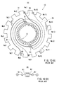
- the rotor R has sixteen armature slots and thirty two commutator segments.
- FIG. 10(A) also shows a wire W2 indicated by dotted lines.
- the wire W2 is connected between a commutator segment No. 17 and a commutator segment No. 1.8 that are offset by an angle of 180° from the commutator segment No. 1 and the commutator segment No. 2, respectively.
- the wire W2 is wound around the armature core 10 through a armature slot No. 16 and a armature slot No. 9 in a manner similar to the wire W1.
- the other wires also are wound around the armature core 10 through the armature slots determined based on the positions of the commutator segments to which the wires are connected.
- the wires W1 and W2 connected to the corresponding commutator segments are wound around the armature core 10 after they have been wound about the neck 14 by about one turn. Therefore, the wires W1 and W2 may contact each other in the region of the neck 14, because the wires W1 and W2 are connected to the commutator segment No. I and the commutator segment No. 17, respectively, which are offset by an angle of 180° relative to each other.
- brushes Br are connected between the commutator segments No. I and No. 2 and between the commutator segments No. 17 and No. 18. Therefore, a voltage that is equal to a power source voltage can be applied between the wire W1 and the wire W2. Further, portions of the wires W1 and W2 positioned in the region of the neck 14 are not so firmly fixed in position in comparison with their portions positioned in the region of the armature slots 11. Therefore, there may be a possibility that the wires W1 and W2 are rub each other due to vibrations during the operation of the motor M. This may cause reduction in thickness of insulation layers of the wires W1 and W2. In particular, in the case of the wires W1 and W2, there is a possibility of causing short-circuiting, because the potential difference between the wires W1 and W2 is large.
- One aspect according to the present invention includes electric motors including an armature core, a commutator including a plurality of commutator segments, a neck disposed between the armature core and the commutator, and a plurality of wires each connected between two adjacent commutator segments and wound around the armature core via the neck.
- the wires include a first wire connected between first two adjacent commutator segments and a second wire connected between second two adjacent commutator segments positioned opposite to the first two adjacent commutator segments with respect to the axis of the armature core.
- the first wire and the second wire extend along the neck such that they do not contact with each other.
- electric motors include an armature core, a commutator, a neck and a plurality of wires.
- the armature core has an axis and defines a plurality of armature slots arranged in a circumferential direction of the armature core.
- the commutator includes a plurality of commutator segments arranged in the circumferential direction of the commutator.
- the commutator has the same axis as the armature core and is spaced from the armature core in an axial direction.
- the neck is disposed between the armature core and the commutator and has a diameter smaller than the commutator.
- Each wire extends along a path in which each wire (a) extends from a first one of the commutator segments to the outer circumference of the neck and extends around a part thereof, (b) extends through a first one of the armature slots of the armature core, turns from the first one of the armature slots to extend through a second one of the armature slots next to the first one of the armature slots, and extends through a third one of the armature slots positioned opposite to the second one of the armature slots with respect to the axis of the armature core, (c) extends around the armature core through the third one and the first one of the armature slots and leaves the first one of the armature slots; or (c') extends around the armature core through the third one and the second one of the armature slots and leaves the third one of the armature slots; and (d) extends around a part of the outer circumference of the neck and extends from the neck to a second one of the
- each wire may be first passed through the first one of the armature slots and may leave from the armature core through the same slot as the first one, or each wire may be first passed through the first one of the armature slots and may leave from the armature core through the second one of the armature slots next to the first one of the armature slots.
- the first one and the second one of the armature slots are offset from the first one and the second one of the commutator segments, respectively, by an angle of approximately 180° about the axis, each of opposite ends of each wire extends around the neck by an angle of approximately 180° or half the circumferential length of the neck.
- a wire No. 1 and a wire No. N will now be considered.
- the wire No. N is connected between two commutator segments, which are positioned opposite to two commutator segments between which the wire No. 1 is connected, and which are offset by an angle of 180° from the two commutator segments between which the wire No I is connected.
- each of opposite ends of each wire is wound around the neck by an angle of about 180° or half the circumferential length of the neck. Therefore, the wire No. 1 and the wire No. N do not contact with each other in the region of the neck.
- a maximum electrical potential difference may be caused between the wire No. 1 and the wire No. N, these wires do not contact with each other in the region of the neck.
- each of opposite ends of each wire is wound around the neck by an angle of about 180° or half the circumferential length of the neck, it is possible to prevent the opposite ends from floating at the neck.
- the wires may include a plurality of pairs of first and second wires, the first and second wires are wound around the armature core through the same two armature slots.
- the first wire may first extend through one of the two armature slots, and the second wire may be first passed through the other of the two armature slots.
- FIGS. 1 to 9 Embodiments of the present invention will now be described with reference to FIGS. 1 to 9 . These embodiments relate to an electric motor for use with a power tool, such as a hammer drill.
- a power tool such as a hammer drill.
- a rotor R of an electric motor M generally includes a shaft 10s defining a rotational axis, an armature core 10 having the same axis as the shaft 10s and fixedly mounted to the shaft 10s at a substantially central position of the shaft 10s along its length, and a commutator 12 also having the same axis as the shaft 10s and fixedly mounted to the shaft 10s at a position proximal to one end of the shaft 10s.
- a neck 14 is defined by a part of the shaft 10s positioned between the armature core 10 and the commutator 12.
- the motor M has sixteen armature slots 11 and thirty two commutator segments 12t. More specifically, the armature slots 11 (hereinafter called “armature slots No. 1 to 16") are formed in the outer circumferential surface of the armature core 10 and spaced equally from each other in the circumferential direction.
- the commutator 12 is divided into the thirty two commutator segments 12t (hereinafter called “commutator segments No.1 to No. 32") spaced equally from each other in the circumferential direction.
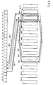
- a first representative method of winding the wires W around the armature core 10 will now be described with reference to FIGS. 1 and 3 to 6 .
- all the wires W are wound around the armature core 10 according to the same pattern of path (hereinafter called "first pattern").
- first wire W11 having one end connected to the commutator segment No. 1 and having the other end connected to the commutator segment No. 2.
- first wire W11 is wound around the left side part of the outer circumference of the neck 14 by about one half of the circumferential length of the neck 14, and thereafter the first wire W11 is passed through the armature slot No. 8 of the armature core 10.
- the armature slot No. 8 is offset from the armature slot No. 1 by an angle of about 180°.
- the first wire W11 is turned from the armature slot No. 8 to be passed through the armature slot No. 9 that is positioned next to the armature slot No. 8.
- the first wire W11 is then passed through the armature slot No. 1 that is positioned at a position opposite to the armature slot No. 9 with respect to the central axis of the armature core 10.
- the first wire W11 is wound around the armature core 10 through the armature slot No. 1 and the armature slot No. 8 by a predetermined number of turns (the first wire W11 is wound only one turn in this embodiment).
- the first wire W11 leaves from the armature slot No. 8 and is wound around the left side part of the outer circumference of the neck 14 by about one half of the circumferential length of the neck 14.
- the other end of the first wire W11 is connected to the commutator segment No. 2.
- the first wire W1 extends along the path of "commutator segment No. 1 - neck 14 - armature slot No. 8 - armature slot No. 9 - armature slot No. I - (winding through slot No. 1 and armature slot No. 8) - armature slot No. 8 - neck 14 - commutator segment No. 2.”
- one end of a second wire W12 is connected to the commutator segment No. 2, so that the other end of the first wire W11 is electrically connected to the second wire W12 via the commutator segment No. 2.
- the second wire W12 is wound around the armature core 10 through the same armature slots and the same order as those for the first wire W1. After leaving from the armature slot No. 8, the other end of the second wire W12 is connected to the commutator segment No. 3.
- the second wire W12 extends along the path of "commutator segment No. 2 - neck 14 - armature slot No. 8 - armature slot No. 9 - armature slot No. I - (winding through slot No. I and armature slot No. 8) - armature slot No. 8 - neck 14 - commutator segment No. 3.”
- one end of a third wire W13 is connected to the commutator segment No. 3, so that the other end of the second wire W12 is electrically connected to the third wire W13 via the commutator segment No. 3.
- the third wire W13 is wound around the armature core 10 through the armature slots that are positioned next to the armature slots through which the second wire W12 is wound around.
- the third wire W13 is wound around the left side part of the outer circumference of the neck 14 by about one half of the circumferential length of the neck 14, and thereafter the third wire W13 is passed through the armature slot No. 9 of the armature core 10.
- the third wire W13 is turned from the armature slot No. 9 to be passed through the armature slot No. 10 that is positioned next to the armature slot No. 9.
- the third wire W13 is then passed through the armature slot No. 2 that is positioned at a position opposite to the armature slot No. 10 with respect to the central axis of the armature core 10.
- the third wire W13 is wound around the armature core 10 through the armature slot No. 2 and the armature slot No. 9 by a predetermined number of turns. Then, the third wire W13 leaves from the armature slot No. 9 and is wound around the left side part of the outer circumference of the neck 14 by about one half of the circumferential length of the neck 14. Finally, the other end of the third wire W13 is connected to the commutator segment No. 4.
- the third wire W13 extends along the path of "commutator segment No. 3 - neck 14 - armature slot No. 9 - armature slot No. 10 - armature slot No. 2 - (winding through slot No. 2 and armature slot No. 9) - armature slot No. 9 - neck 14 - commutator segment No. 4.”
- One end of a fourth wire (not shown) is connected to the commutator segment No. 4, so that the other end of the third wire W13 is electrically connected to the fourth wire via the commutator segment No. 4.
- the fourth wire is wound around the armature core 10 through the same armature slots and the same order as those for the third wire W 13.
- the seventeenth wire W21 that have one end connected to the commutator segment No. 17 and the other end connected to the commutator segment No. 18, because the commutator segments Nos. 17 and 18 are offset from the commutator segment Nos. I and 2 by an angle of about 180°, respectively, the following winding process is applied.
- the seventeenth wire W21 is wound around the right side part of the outer circumference of the neck 14 by about one half of the circumferential length of the neck 14, and thereafter the seventeenth wire W21 is passed through the armature slot No. 16 of the armature core 10.
- the seventeenth W21 is turned from the armature slot No. 16 to be passed through the armature slot No. 1 that is positioned next to the armature slot No. 16.
- the seventeenth wire W21 is then passed through the armature slot No. 9 that is positioned at a position opposite to the armature slot No. 1 with respect to the central axis of the armature core 10.
- the seventeenth wire W21 is wound around the armature core 10 through the armature slot No. 16 and the armature slot No. 9. Then, the seventeenth wire W21 leaves from the armature slot No. 16 and is wound around the right side part of the outer circumference of the neck 14 by about one half of the circumferential length of the neck 14. Finally, the other end of the seventeenth wire W21 is connected to the commutator segment No. 18.
- the seventeenth wire W21 extends along the path of "commutator segment No. 17 - neck 14 - armature slot No. 16 - armature slot No. I - armature slot No. 9 - (winding through slot No. 16 and armature slot No. 9) - armature slot No. 16 - neck 14 - commutator segment No. 18.”
- the armature slot (No. 8) through which the first wire W11 is passed for the first time is the same as the armature slot (No. 8) from which the other end of the first wire W11 leaves.
- the armature slot No. 8 is positioned at a position offset by an angle of about 180° from the commutator segments Nos. 1 and 2. Therefore, each of opposite end portions of the first wire W1 is wound around the neck 14 by about one half of the circumferential length of the neck 14. Therefore, as will be seen from FIG. 1 , the first wire W11 connected between the commutator segments Nos. 1 and 2 and the seventeenth wire W21 connected between the commutator segments Nos. 17 and 18 do not contact with each other in the region of the neck 14.
- the first wire W11 and the seventeenth wire W21 are connected to their respective commutator segments, which are positioned opposite to each other, and therefore, a maximum electrical potential difference may be caused between the first wire W11 and the seventeenth wire W21.
- the first wire W11 and the seventeenth wire W21 do not contact each other in the region of the neck 14 (an area vulnerable to be influenced by vibrations), and therefore, it is possible to prevent or minimize potential short-circuiting between the wires W11 and W12.
- each of opposite end portions of each wire W is wound around the neck 14 by about one half of the circumferential length of the neck 14. Therefore, the opposite end portions of the wires W may not float up in the region of the neck 14.
- the first wire W11 and the seventeenth wire W21 may partly overlap with each other within the armature slot No. I and the armature slot No. 9, the wires W11 and W21 are stably fixed within these armature slots. Hence, the wires W11 and W21 within these armature slots may not be influenced by potential vibrations. As a result, any problems caused due to partial overlapping of the wires W11 and W21, between which a maximum electrical potential difference, may be reduced or eliminated in this configuration..
- first wire WX1 having one end connected to the commutator segment No. 1 and having the other end connected to the commutator segment No. 2.
- the first wire WX1 is wound around the left side part of the outer circumference of the neck 14 by about one half of the circumferential length of the neck 14.
- the first wire WX1 is passed through the armature slot No. 7 of the armature core 10 and is then turned to pass through the armature slot No. 8 positioned next to the armature slot No. 7.
- the first wire WX1 is turned from the armature slot No. 8 to be passed through the armature slot No.
- the first wire WX1 is wound around the armature core 10 through the armature slot No. 1 and the armature slot No. 8 by a predetermined number of turns. Then, the first wire W11 leaves from the armature slot No. 8 and is wound around the left side part of the outer circumference of the neck 14 by about one half of the circumferential length of the neck 14. Finally, the other end of the first wire WX1 is connected to the commutator segment No. 2.
- the first wire WX1 extends along the path of "commutator segment No. I - neck 14 - armature slot No. 7 - armature slot No. 8 - armature slot No. 1 - (winding through slot No. 1 and armature slot No. 8) - armature slot No. 8 - neck 14 - commutator segment No. 2.”
- the first wire WX1 is first passed through the armature slot No. 7 that is different from the armature slot No.8, from which the other end of the first wire WX1 leaves.
- This pattern of path is hereinafter called "second pattern.”
- one end of a second wire WX2 is connected to the commutator segment No. 2.
- the second wire WX2 is then wound around the left side part of the outer circumference of the neck 14 by about one half of the circumferential length of the neck 14, and thereafter the second wire WX2 is passed through the armature slot No. 8 of the armature core 10.
- the second wire WX2 is turned from the armature slot No. 8 to be passed through the armature slot No. 9 that is positioned next to the armature slot No. 8.
- the second wire WX2 is then passed through the armature slot No. 1 that is positioned at a position opposite to the armature slot No. 9 with respect to the central axis of the armature core 10.
- the second WX2 is wound around the armature core 10 through the armature slot No. 1 and the armature slot No. 8 by a predetermined number of turns. Then, the second wire WX2 leaves from the armature slot No. 8 and is wound around the left side part of the outer circumference of the neck 14 by about one half of the circumferential length of the neck 14. Finally, the other end of the second wire WX2 is connected to the commutator segment No. 3.
- the second wire WX2 extends along the path of "commutator segment No. 2 - neck 14 - armature slot No. 8 - armature slot No. 9 - armature slot No. 1 - (winding through slot No. 1 and armature slot No. 8) - armature slot No. 8 - neck 14 - commutator segment No. 3.”
- the second wire WX2 is wound around the armature core according to the first pattern shown in FIGS. 3 to 6 , and therefore, the second wire WX2 is first passed through the same armature slot No.8, from which the other end of the second wire WX2 leaves.
- both the first and second wires WX1 and WX2 are wound around the armature core 10 through the armature slot No. 1 and the armature slot No. 8, the second wire WX1 is first passed through the armature slot No. 8 that is different from the armature slot No. 7 through which the first wire WX1 is first passed.
- a third wire WX3 is wound around the armature core 10 in the second pattern through the armature slots that are positioned next to the armature slots through which the first wire WX1 is wound around.
- the third wire WX3 is wound around the left side part of the outer circumference of the neck 14 by about one half of the circumferential length of the neck 14. Thereafter, the third wire WX3 is passed through the armature slot No. 8 of the armature core 10 and is then turned to pass through the armature slot No. 9. positioned next to the armature slot No. 8. Then, the third wire WX3 is turned from the armature slot No. 9 to be passed through the armature slot No. 2 that is positioned at a position opposite to the armature slot No. 9 with respect to the central axis of the armature core 10.
- the third wire WX3 is wound around the armature core 10 through the armature slot No. 2 and the armature slot No. 9 by a predetermined number of turns. Then, the third wire WX3 leaves from the armature slot No. 9 and is wound around the left side part of the outer circumference of the neck 14 by about one half of the circumferential length of the neck 14. Finally, the other end of the third wire WX3 is connected to the commutator segment No. 4.
- the third wire WX3 extends along the path of "commutator segment No. 3 - neck 14 - armature slot No. 8 - armature slot No. 9 - armature slot No. 2 - (winding through slot No. 2 and armature slot No. 9) - armature slot No. 9 - neck 14 - commutator segment No. 4.”
- a fourth wire (not shown) is wound in the first pattern around the armature core 10 through the armature slots that are positioned next to the armature slots through which the second wire WX2 is wound around.
- the fourth wire is wound around the armature core 10 though the armature slot No. 2 and the armature slot No 9 that are the same as those for the third wire WX3.
- the fourth wire is first passed through a different armature slot from the armature slot through which the third wire WX3 is first passed.
- two wires are wound around the armature core 10 through the same armature slots, and next two wires are wound around the armature core 10 through the armature slots that are respectively positioned next to the armature slots for the previous two wires.
- the remaining wires are wound around the armature core 10 such that any two wires are wound around the armature core 10 through the armature slots that are respectively positioned next to the armature slots for the previous two wires.
- the present invention may not be limited to the above embodiments but may be modified in various ways.
- the wires W are wound only in the first pattern as shown in FIGS. 3 to 6 according to the first method, and the wires W are wound alternatively in the second pattern and the first pattern in this order as shown in FIGS. 7 to 9 according to the second method, the wires may be wound only in the second pattern or alternatively in the first pattern and the second pattern in this order.
- the number of turns of winding the wires W around the armature core 10 may be suitable determined. It is explicitly stated that all features disclosed in the description and/or the claims are intended to be disclosed separately and independently from each other for the purpose of original disclosure as well as for the purpose of restricting the claimed invention independent of the composition of the features in the embodiments and/or the claims. It is explicitly stated that all value ranges or indications of groups of entities disclose every possible intermediate value or intermediate entity for the purpose of original disclosure as well as for the purpose of restricting the claimed invention, in particular as limits of value ranges.
Landscapes
- Engineering & Computer Science (AREA)
- Power Engineering (AREA)
- Dc Machiner (AREA)
- Motor Or Generator Current Collectors (AREA)
- Windings For Motors And Generators (AREA)
- Insulation, Fastening Of Motor, Generator Windings (AREA)
Applications Claiming Priority (1)
| Application Number | Priority Date | Filing Date | Title |
|---|---|---|---|
| JP2007191738A JP5047717B2 (ja) | 2007-07-24 | 2007-07-24 | 電動モータ |
Publications (2)
| Publication Number | Publication Date |
|---|---|
| EP2019478A2 true EP2019478A2 (de) | 2009-01-28 |
| EP2019478A3 EP2019478A3 (de) | 2011-02-09 |
Family
ID=39791181
Family Applications (1)
| Application Number | Title | Priority Date | Filing Date |
|---|---|---|---|
| EP08013202A Withdrawn EP2019478A3 (de) | 2007-07-24 | 2008-07-22 | Elektromotoren |
Country Status (5)
| Country | Link |
|---|---|
| US (1) | US7723890B2 (de) |
| EP (1) | EP2019478A3 (de) |
| JP (1) | JP5047717B2 (de) |
| CN (1) | CN101355275B (de) |
| RU (1) | RU2451381C2 (de) |
Families Citing this family (3)
| Publication number | Priority date | Publication date | Assignee | Title |
|---|---|---|---|---|
| CN101807840B (zh) * | 2009-02-13 | 2016-05-25 | 德昌电机(深圳)有限公司 | 一种永磁直流有刷电机 |
| US9425663B2 (en) | 2012-08-17 | 2016-08-23 | Black & Decker Inc. | Distributed winding arrangement for an electric motor |
| CN117318403A (zh) * | 2023-10-09 | 2023-12-29 | 揭阳市汇宝昌电器有限公司 | 一种反挂线方式的扁形永磁直流有刷电机及其设计方法 |
Citations (2)
| Publication number | Priority date | Publication date | Assignee | Title |
|---|---|---|---|---|
| JPH10210704A (ja) | 1997-01-21 | 1998-08-07 | Makita Corp | 電動モータ |
| JP2007191738A (ja) | 2006-01-17 | 2007-08-02 | Sumitomo Metal Mining Co Ltd | 金属膜を有する成型体およびその製造方法 |
Family Cites Families (19)
| Publication number | Priority date | Publication date | Assignee | Title |
|---|---|---|---|---|
| SU51188A1 (ru) * | 1936-06-08 | 1936-11-30 | П.С. Салита | Якорь машины посто нного тока |
| US2503752A (en) * | 1943-03-06 | 1950-04-11 | Malchus Johannes An Christiaan | Lap wound armature and method of winding it |
| SU545045A1 (ru) * | 1974-01-16 | 1977-01-30 | Ленинградский Ордена Ленина Политехнический Институт Им.М.И.Калинина | Якорна обмотка коллекторной электрической машины |
| SU1270838A1 (ru) * | 1983-07-11 | 1986-11-15 | Харьковский Ордена Ленина Политехнический Институт Им.В.И.Ленина | Электрическа машина |
| DE3631943A1 (de) * | 1986-09-19 | 1988-04-07 | Siemens Ag | Kommutatormotor mit isolierabdeckung der rotorwelle |
| NL8902180A (nl) * | 1989-08-29 | 1991-03-18 | Philips Nv | Werkwijze voor het bewikkelen van een ankerlichaam van een anker, alsmede electrische machine voorzien van een anker vervaardigd volgens de werkwijze. |
| US5994812A (en) * | 1996-10-29 | 1999-11-30 | Siemens Canada Limited | D.C. motor phase windings and their commutation |
| JP3278402B2 (ja) * | 1998-08-07 | 2002-04-30 | 三菱電機株式会社 | 回転電機 |
| JP3559171B2 (ja) * | 1998-08-10 | 2004-08-25 | 三菱電機株式会社 | 回転電機の整流子及びその製造方法 |
| JP3559172B2 (ja) * | 1998-08-10 | 2004-08-25 | 三菱電機株式会社 | 回転電機のアマチュア及びその製造方法 |
| JP3530034B2 (ja) * | 1998-08-10 | 2004-05-24 | 三菱電機株式会社 | 回転電機の整流装置 |
| JP3559178B2 (ja) * | 1998-10-23 | 2004-08-25 | 三菱電機株式会社 | 回転電機及びその製造方法 |
| DE19934685A1 (de) * | 1999-07-23 | 2001-01-25 | Interelectric Ag Sachseln | Elektrokleinmotor mit Funkenunterdrückungseinrichtung |
| JP3469164B2 (ja) * | 2000-05-02 | 2003-11-25 | 三菱電機株式会社 | 回転電機 |
| US6566782B1 (en) * | 2000-06-14 | 2003-05-20 | Black & Decker Inc. | Motor armature having distributed windings for reducing arcing |
| JP2003102155A (ja) * | 2002-09-06 | 2003-04-04 | Mitsubishi Electric Corp | 整流子電動機 |
| US7583004B2 (en) * | 2003-10-06 | 2009-09-01 | Asmo Co., Ltd. | Short-circuiting member, commutator, and method of manufacturing short-circuiting member |
| DE10361811A1 (de) * | 2003-12-30 | 2005-07-28 | Robert Bosch Gmbh | Elektrische Maschine mit Kommutatorläufer |
| JP4772508B2 (ja) * | 2004-02-10 | 2011-09-14 | 株式会社ミツバ | 電動モータ |
-
2007
- 2007-07-24 JP JP2007191738A patent/JP5047717B2/ja not_active Expired - Fee Related
-
2008
- 2008-06-02 CN CN2008101095658A patent/CN101355275B/zh not_active Expired - Fee Related
- 2008-07-18 US US12/219,288 patent/US7723890B2/en not_active Expired - Fee Related
- 2008-07-22 EP EP08013202A patent/EP2019478A3/de not_active Withdrawn
- 2008-07-23 RU RU2008130530/07A patent/RU2451381C2/ru not_active IP Right Cessation
Patent Citations (2)
| Publication number | Priority date | Publication date | Assignee | Title |
|---|---|---|---|---|
| JPH10210704A (ja) | 1997-01-21 | 1998-08-07 | Makita Corp | 電動モータ |
| JP2007191738A (ja) | 2006-01-17 | 2007-08-02 | Sumitomo Metal Mining Co Ltd | 金属膜を有する成型体およびその製造方法 |
Also Published As
| Publication number | Publication date |
|---|---|
| CN101355275A (zh) | 2009-01-28 |
| RU2008130530A (ru) | 2010-01-27 |
| US7723890B2 (en) | 2010-05-25 |
| CN101355275B (zh) | 2013-01-02 |
| JP2009027902A (ja) | 2009-02-05 |
| JP5047717B2 (ja) | 2012-10-10 |
| RU2451381C2 (ru) | 2012-05-20 |
| EP2019478A3 (de) | 2011-02-09 |
| US20090026871A1 (en) | 2009-01-29 |
Similar Documents
| Publication | Publication Date | Title |
|---|---|---|
| AU2012265599B2 (en) | Electric motor | |
| US10050484B2 (en) | Stator for rotating electric machine | |
| CN100570996C (zh) | 电动机 | |
| US8461738B2 (en) | Single-layer coil with one bent endwinding and one straight endwinding | |
| JP2000139049A (ja) | 車両用交流発電機およびそのステータの製造方法 | |
| JP5060325B2 (ja) | 回転電機の電機子巻線 | |
| US10056797B2 (en) | Stator for rotating electric machine | |
| JP2020167788A5 (de) | ||
| WO2009096426A1 (ja) | 電動モータ | |
| CN113708521B (zh) | 一种卷绕的电机定子及电机 | |
| JP2008245489A (ja) | 回転電機の固定子 | |
| US20040232780A1 (en) | Stator for a rotary electric machine | |
| US20100264772A1 (en) | Direct current motor | |
| US20130049514A1 (en) | Electric rotating machine | |
| US9337695B2 (en) | Single-layer coil with one bent endwinding and one straight endwinding | |
| US7723890B2 (en) | Electric motors | |
| US9438079B2 (en) | Armature end insulator for a power tool motor | |
| US11183897B2 (en) | Stator of rotating electric apparatus | |
| CN102545442B (zh) | 用于电机的电枢,该电枢的制造方法以及电机 | |
| JP4886458B2 (ja) | 電動モータ用アーマチュア、電動モータ及び電動モータ用アーマチュアの巻線方法 | |
| JP6047070B2 (ja) | 電機子及び電機子の製造方法 | |
| CN103329404B (zh) | 具有多个相绕组的定子绕组 | |
| JP2010011565A (ja) | 電動モータにおけるアーマチュアおよびその製造方法 | |
| US9425663B2 (en) | Distributed winding arrangement for an electric motor | |
| CN113595346B (zh) | 定子组件的绕组绕线方法、定子组件以及电机 |
Legal Events
| Date | Code | Title | Description |
|---|---|---|---|
| PUAI | Public reference made under article 153(3) epc to a published international application that has entered the european phase |
Free format text: ORIGINAL CODE: 0009012 |
|
| AK | Designated contracting states |
Kind code of ref document: A2 Designated state(s): AT BE BG CH CY CZ DE DK EE ES FI FR GB GR HR HU IE IS IT LI LT LU LV MC MT NL NO PL PT RO SE SI SK TR |
|
| AX | Request for extension of the european patent |
Extension state: AL BA MK RS |
|
| RIC1 | Information provided on ipc code assigned before grant |
Ipc: H02K 13/04 20060101ALI20100802BHEP Ipc: H02K 23/26 20060101AFI20081009BHEP |
|
| PUAL | Search report despatched |
Free format text: ORIGINAL CODE: 0009013 |
|
| AK | Designated contracting states |
Kind code of ref document: A3 Designated state(s): AT BE BG CH CY CZ DE DK EE ES FI FR GB GR HR HU IE IS IT LI LT LU LV MC MT NL NO PL PT RO SE SI SK TR |
|
| AX | Request for extension of the european patent |
Extension state: AL BA MK RS |
|
| 17P | Request for examination filed |
Effective date: 20110809 |
|
| AKX | Designation fees paid |
Designated state(s): AT BE BG CH CY CZ DE DK EE ES FI FR GB GR HR HU IE IS IT LI LT LU LV MC MT NL NO PL PT RO SE SI SK TR |
|
| 17Q | First examination report despatched |
Effective date: 20110920 |
|
| STAA | Information on the status of an ep patent application or granted ep patent |
Free format text: STATUS: THE APPLICATION IS DEEMED TO BE WITHDRAWN |
|
| 18D | Application deemed to be withdrawn |
Effective date: 20160202 |