EP2019480A2 - Stromversorgungsschaltung einer Bildanzeigevorrichtung - Google Patents
Stromversorgungsschaltung einer Bildanzeigevorrichtung Download PDFInfo
- Publication number
- EP2019480A2 EP2019480A2 EP08157229A EP08157229A EP2019480A2 EP 2019480 A2 EP2019480 A2 EP 2019480A2 EP 08157229 A EP08157229 A EP 08157229A EP 08157229 A EP08157229 A EP 08157229A EP 2019480 A2 EP2019480 A2 EP 2019480A2
- Authority
- EP
- European Patent Office
- Prior art keywords
- voltage
- image display
- display apparatus
- diode
- power source
- Prior art date
- Legal status (The legal status is an assumption and is not a legal conclusion. Google has not performed a legal analysis and makes no representation as to the accuracy of the status listed.)
- Withdrawn
Links
Images

Classifications
-
- H—ELECTRICITY
- H02—GENERATION; CONVERSION OR DISTRIBUTION OF ELECTRIC POWER
- H02J—ELECTRIC POWER NETWORKS; CIRCUIT ARRANGEMENTS OR SYSTEMS FOR SUPPLYING OR DISTRIBUTING ELECTRIC POWER; SYSTEMS FOR STORING ELECTRIC ENERGY
- H02J9/00—Circuit arrangements for emergency or stand-by power supply, e.g. for emergency lighting
- H02J9/005—Circuit arrangements for emergency or stand-by power supply, e.g. for emergency lighting using a power saving mode
-
- H—ELECTRICITY
- H02—GENERATION; CONVERSION OR DISTRIBUTION OF ELECTRIC POWER
- H02M—APPARATUS FOR CONVERSION BETWEEN AC AND AC, BETWEEN AC AND DC, OR BETWEEN DC AND DC, AND FOR USE WITH MAINS OR SIMILAR POWER SUPPLY SYSTEMS; CONVERSION OF DC OR AC INPUT POWER INTO SURGE OUTPUT POWER; CONTROL OR REGULATION THEREOF
- H02M1/00—Details of apparatus for conversion
- H02M1/16—Means for providing current step on switching, e.g. with saturable reactor
-
- H—ELECTRICITY
- H02—GENERATION; CONVERSION OR DISTRIBUTION OF ELECTRIC POWER
- H02M—APPARATUS FOR CONVERSION BETWEEN AC AND AC, BETWEEN AC AND DC, OR BETWEEN DC AND DC, AND FOR USE WITH MAINS OR SIMILAR POWER SUPPLY SYSTEMS; CONVERSION OF DC OR AC INPUT POWER INTO SURGE OUTPUT POWER; CONTROL OR REGULATION THEREOF
- H02M7/00—Conversion of AC power input into DC power output; Conversion of DC power input into AC power output
- H02M7/02—Conversion of AC power input into DC power output without possibility of reversal
- H02M7/04—Conversion of AC power input into DC power output without possibility of reversal by static converters
- H02M7/06—Conversion of AC power input into DC power output without possibility of reversal by static converters using discharge tubes without control electrode or semiconductor devices without control electrode
- H02M7/064—Conversion of AC power input into DC power output without possibility of reversal by static converters using discharge tubes without control electrode or semiconductor devices without control electrode with several outputs
-
- H—ELECTRICITY
- H02—GENERATION; CONVERSION OR DISTRIBUTION OF ELECTRIC POWER
- H02M—APPARATUS FOR CONVERSION BETWEEN AC AND AC, BETWEEN AC AND DC, OR BETWEEN DC AND DC, AND FOR USE WITH MAINS OR SIMILAR POWER SUPPLY SYSTEMS; CONVERSION OF DC OR AC INPUT POWER INTO SURGE OUTPUT POWER; CONTROL OR REGULATION THEREOF
- H02M7/00—Conversion of AC power input into DC power output; Conversion of DC power input into AC power output
- H02M7/02—Conversion of AC power input into DC power output without possibility of reversal
- H02M7/04—Conversion of AC power input into DC power output without possibility of reversal by static converters
- H02M7/06—Conversion of AC power input into DC power output without possibility of reversal by static converters using discharge tubes without control electrode or semiconductor devices without control electrode
- H02M7/066—Conversion of AC power input into DC power output without possibility of reversal by static converters using discharge tubes without control electrode or semiconductor devices without control electrode particular circuits having a special characteristic
-
- H—ELECTRICITY
- H02—GENERATION; CONVERSION OR DISTRIBUTION OF ELECTRIC POWER
- H02M—APPARATUS FOR CONVERSION BETWEEN AC AND AC, BETWEEN AC AND DC, OR BETWEEN DC AND DC, AND FOR USE WITH MAINS OR SIMILAR POWER SUPPLY SYSTEMS; CONVERSION OF DC OR AC INPUT POWER INTO SURGE OUTPUT POWER; CONTROL OR REGULATION THEREOF
- H02M1/00—Details of apparatus for conversion
- H02M1/0003—Details of control, feedback or regulation circuits
- H02M1/0032—Control circuits allowing low power mode operation, e.g. in standby mode
-
- H—ELECTRICITY
- H02—GENERATION; CONVERSION OR DISTRIBUTION OF ELECTRIC POWER
- H02M—APPARATUS FOR CONVERSION BETWEEN AC AND AC, BETWEEN AC AND DC, OR BETWEEN DC AND DC, AND FOR USE WITH MAINS OR SIMILAR POWER SUPPLY SYSTEMS; CONVERSION OF DC OR AC INPUT POWER INTO SURGE OUTPUT POWER; CONTROL OR REGULATION THEREOF
- H02M7/00—Conversion of AC power input into DC power output; Conversion of DC power input into AC power output
- H02M7/02—Conversion of AC power input into DC power output without possibility of reversal
- H02M7/04—Conversion of AC power input into DC power output without possibility of reversal by static converters
- H02M7/05—Capacitor coupled rectifiers
-
- Y—GENERAL TAGGING OF NEW TECHNOLOGICAL DEVELOPMENTS; GENERAL TAGGING OF CROSS-SECTIONAL TECHNOLOGIES SPANNING OVER SEVERAL SECTIONS OF THE IPC; TECHNICAL SUBJECTS COVERED BY FORMER USPC CROSS-REFERENCE ART COLLECTIONS [XRACs] AND DIGESTS
- Y02—TECHNOLOGIES OR APPLICATIONS FOR MITIGATION OR ADAPTATION AGAINST CLIMATE CHANGE
- Y02B—CLIMATE CHANGE MITIGATION TECHNOLOGIES RELATED TO BUILDINGS, e.g. HOUSING, HOUSE APPLIANCES OR RELATED END-USER APPLICATIONS
- Y02B70/00—Technologies for an efficient end-user side electric power management and consumption
- Y02B70/10—Technologies improving the efficiency by using switched-mode power supplies [SMPS], i.e. efficient power electronics conversion e.g. power factor correction or reduction of losses in power supplies or efficient standby modes
-
- Y—GENERAL TAGGING OF NEW TECHNOLOGICAL DEVELOPMENTS; GENERAL TAGGING OF CROSS-SECTIONAL TECHNOLOGIES SPANNING OVER SEVERAL SECTIONS OF THE IPC; TECHNICAL SUBJECTS COVERED BY FORMER USPC CROSS-REFERENCE ART COLLECTIONS [XRACs] AND DIGESTS
- Y02—TECHNOLOGIES OR APPLICATIONS FOR MITIGATION OR ADAPTATION AGAINST CLIMATE CHANGE
- Y02B—CLIMATE CHANGE MITIGATION TECHNOLOGIES RELATED TO BUILDINGS, e.g. HOUSING, HOUSE APPLIANCES OR RELATED END-USER APPLICATIONS
- Y02B70/00—Technologies for an efficient end-user side electric power management and consumption
- Y02B70/30—Systems integrating technologies related to power network operation and communication or information technologies for improving the carbon footprint of the management of residential or tertiary loads, i.e. smart grids as climate change mitigation technology in the buildings sector, including also the last stages of power distribution and the control, monitoring or operating management systems at local level
-
- Y—GENERAL TAGGING OF NEW TECHNOLOGICAL DEVELOPMENTS; GENERAL TAGGING OF CROSS-SECTIONAL TECHNOLOGIES SPANNING OVER SEVERAL SECTIONS OF THE IPC; TECHNICAL SUBJECTS COVERED BY FORMER USPC CROSS-REFERENCE ART COLLECTIONS [XRACs] AND DIGESTS
- Y04—INFORMATION OR COMMUNICATION TECHNOLOGIES HAVING AN IMPACT ON OTHER TECHNOLOGY AREAS
- Y04S—SYSTEMS INTEGRATING TECHNOLOGIES RELATED TO POWER NETWORK OPERATION, COMMUNICATION OR INFORMATION TECHNOLOGIES FOR IMPROVING THE ELECTRICAL POWER GENERATION, TRANSMISSION, DISTRIBUTION, MANAGEMENT OR USAGE, i.e. SMART GRIDS
- Y04S20/00—Management or operation of end-user stationary applications or the last stages of power distribution; Controlling, monitoring or operating thereof
- Y04S20/20—End-user application control systems
Definitions
- Circuits consistent with the present invention relate to a power supply circuit, and more particularly, to a power supply circuit of an image display apparatus which supplies power both in standby and operation modes.
- An image display apparatus such as a digital light processing (DLP) apparatus, a projector, a liquid crystal display (LCD), or a plasma display panel (PDP) requires high voltage to process and display an image signal on screen.
- DLP digital light processing
- LCD liquid crystal display
- PDP plasma display panel
- An image display apparatus maintains a standby state that uses lower voltage, when the apparatus is not operated.
- a power supply circuit operates to supply power according to operational modes of an image display apparatus. The power supply circuit will be explained below with reference to FIG. 1 .
- FIG. 1 illustrates the structure of a power supply circuit used in a related art image display apparatus.
- an image display apparatus receives power from an external AC power source 10, and includes a switch 20, a first rectifier 30, an optical source driving unit 40, a main DC-DC converter 50, a second rectifier 60, and a sub DC-DC converter 80.
- the switch 20 In standby mode, power from the AC power source 10 is fed to the sub DC-DC converter 80 through the second rectifier 60.
- the switch 20 In the standby mode, the switch 20 is off, and the second rectifier receives AC voltage from the AC power source 10 by four diodes D5, D6, D7, D8, connected in a bridge circuit, and a capacitor C3 and outputs the AC voltage into a DC voltage.
- the DC voltage from the second rectifier 60 is fed to the sub DC-DC converter 80.
- the voltage from the AC power source 10 is fed to the optical source driving unit 40 and the main DC-DC converter 50 through the first rectifier 30. Accordingly, AC voltage of the AC power source 10 is output as a DC voltage through four diodes D1, D2, D3, D4 in a bridge circuit and two voltage doubler capacitors C1, C2.
- a related image display apparatus uses a separate sub DC-DC converter 80 in a standby mode, and the manufacturing cost is thus increased.
- the sub DC-DC converter 80 may be omitted to reduce the manufacturing cost, but this will lead to increased power consumption.
- Exemplary embodiments of the present invention overcome the above disadvantages and other disadvantages not described above. Also, the present invention is not required to overcome the disadvantages described above, and an exemplary embodiment of the present invention may not overcome any of the problems described above.
- the present invention provides a power supply circuit of an image display apparatus capable of discriminating a standby mode and an operating mode and supplying voltage according to the determined mode, using a single DC-DC converter, which consumes less power and is economical.
- a power supply circuit including a voltage converter which outputs a voltage suitable for a standby state and an operating state, a rectifier which converts an AC voltage being fed from an external AC power source into a DC voltage and outputs the DC voltage to the voltage converter, in the standby state, and a diode unit which prevents ingress of the DC voltage being output from the rectifier into another circuit.
- An anode of the diode unit may be connected to the other circuit, and a cathode of the diode unit may be connected to the voltage converter, thereby preventing ingress of the DC voltage to the other circuit.
- the rectifier may include a first diode, of which an anode is connected to the AC power source and a cathode is connected to the voltage converter, and which is turned ON when (+) voltage is supplied from the AC power source, and a capacitor which is charged when the first diode is ON, and which outputs the charged voltage to the voltage converter when (-) voltage is supplied from the AC power source.
- the power supply circuit may further include a main rectifier which steps up an AC voltage being supplied from the AC power source into a DC voltage and outputs the DC voltage as a high voltage, in the operating state, and a driving unit which drives according to the high voltage received from the main rectifier.
- An anode of the diode unit may be connected to the driving unit, and a cathode of the diode unit may be connected to the voltage converter, thereby preventing ingress of the DC voltage to the driving unit.
- the present invention also provides an image display apparatus, including a voltage converter which outputs voltage necessary for a standby mode and an operating mode, a rectifier which converts an AC voltage being fed from an external AC power source into a DC voltage and outputs the DC voltage to the voltage converter, in the standby state, and a diode unit which prevents ingress of the DC voltage being output from the rectifier into another circuit.
- An anode of the diode unit may be connected to the other circuit, and a cathode of the diode unit may be connected to the voltage converter, thereby preventing ingress of the DC voltage to the another circuit.
- the rectifier may include a first diode, of which an anode is connected to the AC power source and a cathode is connected to the voltage converter, and which is turned ON when (+) voltage is supplied from the AC power source, and a capacitor which is charged when the first diode is ON, and which outputs the charged voltage to the voltage converter when (-) voltage is supplied from the AC power source.
- the image display apparatus may further include a main rectifier which steps up an AC voltage being supplied from the AC power source into a DC voltage and outputs the DC voltage as a high voltage, in the operating state, and a driving unit which drives according to the high voltage received from the main rectifier.
- a main rectifier which steps up an AC voltage being supplied from the AC power source into a DC voltage and outputs the DC voltage as a high voltage, in the operating state
- a driving unit which drives according to the high voltage received from the main rectifier.
- An anode of the diode unit may be connected to the driving unit, and a cathode of the diode unit may be connected to the voltage converter, thereby preventing ingress of the DC voltage to the driving unit.
- the image display apparatus may be one of a liquid crystal display (LCD), a digital light processing (DLP) apparatus, and a projector.
- LCD liquid crystal display
- DLP digital light processing
- FIG. 1 illustrates the structure of a power supply circuit used in a related art image display apparatus
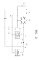
- FIG. 2 illustrates the structure of a power supply circuit used in an image display apparatus according to an exemplary embodiment of the present invention
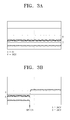
- FIGS. 3A and 3B illustrate waveforms to explain the operation of a power supply circuit according to an exemplary embodiment of the present invention.
- FIG. 2 illustrates the structure of a power supply circuit used in an image display apparatus according to an exemplary embodiment of the present invention.
- an image display apparatus receives power from an external AC power source 110, and includes a switch 120, a first rectifier 130, an optical source driving unit 150, a diode unit 160, a second rectifier 170, and a DC-DC converter 180.
- the first diode D5 When the image display apparatus is in a standby state, the first diode D5 is ON when (+) voltage is supplied from the AC power source 110. That is, because an anode of the first diode D5 is connected to the AC power source 110, and a cathode of the first diode D5 is connected with the DC-DC converter 180, the first diode D5 is turned ON when (+) voltage is supplied from the AC power source 110.
- the capacitor C3 is charged with (+) voltage fed from the AC power source 110, and as a result, a DC voltage is supplied to the DC-DC converter 180.
- the first diode D5 is turned OFF when (-) voltage is supplied from the AC power source 110. Accordingly, voltage charged at the capacitor C3 is supplied to the DC-DC converter 180.
- the second diode D6 is turned OFF, preventing DC voltage being supplied to the DC-DC converter 180 from being leaked to circuits other than the DC-DC converter 180.
- An anode of the second diode D6 is connected to the optical source driving unit 150, and a cathode of the second diode D6 is connected to the DC-DC converter 180, to thus prevent power supply to the optical source driving unit 150 in standby state.
- the switch 120 is ON, and AC voltage of the AC power source 110 is output as DC voltage through the first rectifier 130, the two capacitors C1, C2 step up the voltage being output from the four bridge diodes D1, D2, D3, D4 according to the capacitance thereof and output high voltage.
- the output high voltage is supplied to the optical source driving unit 150 and the DC-DC converter 180.
- the second diode D6 is turned ON to supply the high voltage being output from the first rectifier 130 to the DC-DC converter 180.
- the second diode D6 is turned OFF when the image display apparatus is in a standby state, preventing voltage from the AC power source 110 from being supplied to circuits that require high voltage such as optical source driving unit 150.
- the second diode D6 is turned On when the image display apparatus is in operating mode, causing DC voltage to be supplied to the DC-DC converter 180 through the first rectifier 130.
- the first rectifier 130 may be constructed based on power factor correction (PFC), instead of employing two capacitors C1, C2.
- PFC power factor correction
- the image display apparatus may be implemented as an apparatus that employs a light source, such as, for example, a liquid crystal display (LCD), a digital light processing (DLP) apparatus, or a projector.
- a light source such as, for example, a liquid crystal display (LCD), a digital light processing (DLP) apparatus, or a projector.
- the image display apparatus may be implemented as an apparatus that does not employ a light source, such as, for example, a plasma display panel (PDP) or a cathode-ray tube (CRT).
- PDP plasma display panel
- CRT cathode-ray tube
- FIGS. 3A and 3B illustrate waveforms to explain the operation of a power supply circuit according to an exemplary embodiment of the present invention.
- FIG. 3A particularly shows the waveform of DC voltage at A and B nodes when the image display apparatus is in standby mode.
- the second diode (D6) is OFF, and A and B nodes have different levels of DC voltage. Specifically, if AC voltage of 120V is supplied from the AC power source 110, the second diode D6 shunts off the voltage, causing A node to have 0V of DC voltage and B node to have 160V of DC voltage.
- FIG. 3B particularly shows the waveform of DC voltage when the image display apparatus is in operating mode. Because the second diode D6 is ON in the operating state, A and B nodes have the same level of DC voltage. Specifically, because voltage being output from the first rectifier 130 is larger than voltage being output from the first diode D5 and the capacitor C3, the second diode D6 is turned ON. As a result, if AC voltage of 120V is supplied from the AC power source 110, A and B nodes have the same level of DC voltage, that is 340V.
- the exemplary embodiments of the present invention employ a single DC-DC converter in supplying power, by discriminatingly supplying power according to standby and operating modes of the image display apparatus. As a result, power consumption and manufacturing costs decrease.
Landscapes
- Engineering & Computer Science (AREA)
- Power Engineering (AREA)
- Business, Economics & Management (AREA)
- Emergency Management (AREA)
- Control Of Indicators Other Than Cathode Ray Tubes (AREA)
- Liquid Crystal (AREA)
- Control Of El Displays (AREA)
- Television Receiver Circuits (AREA)
Applications Claiming Priority (1)
| Application Number | Priority Date | Filing Date | Title |
|---|---|---|---|
| KR1020070075672A KR101329620B1 (ko) | 2007-07-27 | 2007-07-27 | 영상표시장치의 전원공급회로 |
Publications (2)
| Publication Number | Publication Date |
|---|---|
| EP2019480A2 true EP2019480A2 (de) | 2009-01-28 |
| EP2019480A3 EP2019480A3 (de) | 2015-09-23 |
Family
ID=39864856
Family Applications (1)
| Application Number | Title | Priority Date | Filing Date |
|---|---|---|---|
| EP08157229.9A Withdrawn EP2019480A3 (de) | 2007-07-27 | 2008-05-29 | Stromversorgungsschaltung einer Bildanzeigevorrichtung |
Country Status (3)
| Country | Link |
|---|---|
| US (1) | US20090027929A1 (de) |
| EP (1) | EP2019480A3 (de) |
| KR (1) | KR101329620B1 (de) |
Cited By (1)
| Publication number | Priority date | Publication date | Assignee | Title |
|---|---|---|---|---|
| US8960925B2 (en) | 2011-02-16 | 2015-02-24 | Benq Corporation | Projector display module and power saving method thereof |
Families Citing this family (6)
| Publication number | Priority date | Publication date | Assignee | Title |
|---|---|---|---|---|
| ES2406181B1 (es) * | 2011-03-11 | 2014-05-21 | BSH Electrodomésticos España S.A. | Aparato doméstico con un modo en espera, y procedimiento para accionar tal aparato doméstico |
| KR20130090122A (ko) * | 2012-02-03 | 2013-08-13 | 삼성전자주식회사 | 가전기기의 전원 장치 |
| JP6335438B2 (ja) * | 2013-05-17 | 2018-05-30 | キヤノン株式会社 | スイッチ制御装置及び画像形成装置 |
| US9490704B2 (en) * | 2014-02-12 | 2016-11-08 | Delta Electronics, Inc. | System and methods for controlling secondary side switches in resonant power converters |
| CN113595412B (zh) * | 2021-08-27 | 2023-08-18 | 康佳集团股份有限公司 | 一种llc电路及开关电源 |
| KR102931812B1 (ko) * | 2023-06-08 | 2026-02-25 | 엘지전자 주식회사 | 영상표시장치 |
Family Cites Families (21)
| Publication number | Priority date | Publication date | Assignee | Title |
|---|---|---|---|---|
| JPS6070698A (ja) * | 1983-09-27 | 1985-04-22 | Toshiba Corp | X線管フイラメント加熱装置 |
| DE3417049C1 (de) * | 1984-05-09 | 1985-12-05 | Deutsche Thomson-Brandt Gmbh, 7730 Villingen-Schwenningen | Schaltungsanordnung für den stand-by-Betrieb |
| KR960007869Y1 (ko) * | 1993-12-30 | 1996-09-18 | 엘지전자 주식회사 | 스탠바이회로 |
| GB2307802B (en) * | 1995-12-01 | 2000-06-07 | Ibm | Power supply with power factor correction circuit |
| US6104622A (en) * | 1997-04-30 | 2000-08-15 | Fidelix Y.K. | Power supply apparatus for reduction of power consumption |
| KR100219659B1 (ko) * | 1997-08-27 | 1999-09-01 | 윤종용 | 인쇄기용 전원공급제어장치 |
| JP2000116027A (ja) * | 1998-03-10 | 2000-04-21 | Fiderikkusu:Kk | 電源装置 |
| JP2000014043A (ja) * | 1998-06-05 | 2000-01-14 | Internatl Business Mach Corp <Ibm> | 無停電電源装置 |
| TW421740B (en) * | 1999-01-13 | 2001-02-11 | Acer Peripherals Inc | Power source circuit of the electronic apparatus |
| US7129599B2 (en) * | 2002-10-15 | 2006-10-31 | Soft Switching Technologies Corporation | Dual feed power supply systems with enhanced power quality |
| DE10327956B4 (de) | 2003-06-20 | 2011-04-14 | Infineon Technologies Ag | Schaltungsanordnung zur Spannungsversorgung einer Last |
| GB0321321D0 (en) * | 2003-09-11 | 2003-10-15 | Boc Group Plc | Power factor correction circuit |
| US6967851B2 (en) * | 2003-12-15 | 2005-11-22 | System General Corp. | Apparatus for reducing the power consumption of a PFC-PWM power converter |
| KR20060040046A (ko) * | 2004-11-04 | 2006-05-10 | 삼성에스디아이 주식회사 | 플라즈마 표시 장치와 그의 전원 공급 장치 |
| JP2006271182A (ja) * | 2005-02-25 | 2006-10-05 | Rohm Co Ltd | 昇降圧レギュレータ回路及びこれを用いた液晶表示装置 |
| KR100627398B1 (ko) * | 2005-06-01 | 2006-09-22 | 삼성에스디아이 주식회사 | 전원 공급 장치 |
| JP4774987B2 (ja) * | 2005-12-28 | 2011-09-21 | サンケン電気株式会社 | スイッチング電源装置 |
| JP2007282411A (ja) * | 2006-04-10 | 2007-10-25 | Rohm Co Ltd | 昇圧型dc/dcコンバータ及びこれを備えた電子機器 |
| JP5208374B2 (ja) * | 2006-04-18 | 2013-06-12 | シャープ株式会社 | 系統連系パワーコンディショナおよび系統連系電源システム |
| US8461915B2 (en) * | 2009-06-03 | 2013-06-11 | System General Corp. | Start-up circuit to discharge EMI filter for power saving of power supplies |
| WO2012140840A1 (ja) * | 2011-04-14 | 2012-10-18 | パナソニック株式会社 | コンバータ装置及び半導体装置 |
-
2007
- 2007-07-27 KR KR1020070075672A patent/KR101329620B1/ko not_active Expired - Fee Related
-
2008
- 2008-04-01 US US12/060,470 patent/US20090027929A1/en not_active Abandoned
- 2008-05-29 EP EP08157229.9A patent/EP2019480A3/de not_active Withdrawn
Cited By (1)
| Publication number | Priority date | Publication date | Assignee | Title |
|---|---|---|---|---|
| US8960925B2 (en) | 2011-02-16 | 2015-02-24 | Benq Corporation | Projector display module and power saving method thereof |
Also Published As
| Publication number | Publication date |
|---|---|
| KR20090011758A (ko) | 2009-02-02 |
| KR101329620B1 (ko) | 2013-11-15 |
| US20090027929A1 (en) | 2009-01-29 |
| EP2019480A3 (de) | 2015-09-23 |
Similar Documents
| Publication | Publication Date | Title |
|---|---|---|
| EP2019480A2 (de) | Stromversorgungsschaltung einer Bildanzeigevorrichtung | |
| US8179053B2 (en) | Power supply for an LCD display | |
| KR101243402B1 (ko) | 액정표시소자의 하이브리드 백라이트 구동 장치 | |
| EP1176580A2 (de) | Schaltung zum Steuern eines organischen elektrolumineszenten Geräts | |
| US20090015068A1 (en) | Apparatus for supplying power and liquid crystal display having the same | |
| CN1213391C (zh) | 等离子体显示装置 | |
| CN1624534A (zh) | 电源系统和具有该系统的液晶显示器件 | |
| US7768806B2 (en) | Mixed-code DC/AC inverter | |
| US7777425B2 (en) | Backlight circuit for LCD panel | |
| KR20080040230A (ko) | 액정 표시 장치 | |
| KR101422024B1 (ko) | 평판디스플레이의 전원공급장치 | |
| US20070052370A1 (en) | Multi-lamp driving system | |
| CN101317324B (zh) | 电力供给装置及使用了它的发光装置和电子设备 | |
| JP2005353572A (ja) | 蛍光管駆動装置、液晶ディスプレイ装置 | |
| US7759875B2 (en) | Backlight module and current providing circuit thereof | |
| US8436540B2 (en) | Multi-lamp driving system | |
| KR20060109732A (ko) | 백 라이트의 구동장치 및 구동방법 | |
| US7888824B2 (en) | Independent power supply module for LCD | |
| JP3846803B2 (ja) | 放電灯駆動装置及び液晶表示装置 | |
| US20070103942A1 (en) | Backlight module, inverter, and DC voltage generating method thereof | |
| US7633238B2 (en) | Lamp driving device and display apparatus having the same | |
| JP2009009721A (ja) | 放電灯点灯装置 | |
| JP5267357B2 (ja) | 昇圧回路、光源装置および液晶表示装置 | |
| KR100599787B1 (ko) | 전원 공급 장치 및 이의 ic 바이어스 전압 공급 방법 | |
| KR101070027B1 (ko) | 플라즈마 디스플레이 패널용 구동 장치 |
Legal Events
| Date | Code | Title | Description |
|---|---|---|---|
| PUAI | Public reference made under article 153(3) epc to a published international application that has entered the european phase |
Free format text: ORIGINAL CODE: 0009012 |
|
| AK | Designated contracting states |
Kind code of ref document: A2 Designated state(s): AT BE BG CH CY CZ DE DK EE ES FI FR GB GR HR HU IE IS IT LI LT LU LV MC MT NL NO PL PT RO SE SI SK TR |
|
| AX | Request for extension of the european patent |
Extension state: AL BA MK RS |
|
| RAP1 | Party data changed (applicant data changed or rights of an application transferred) |
Owner name: SAMSUNG ELECTRONICS CO., LTD. |
|
| PUAL | Search report despatched |
Free format text: ORIGINAL CODE: 0009013 |
|
| AK | Designated contracting states |
Kind code of ref document: A3 Designated state(s): AT BE BG CH CY CZ DE DK EE ES FI FR GB GR HR HU IE IS IT LI LT LU LV MC MT NL NO PL PT RO SE SI SK TR |
|
| AX | Request for extension of the european patent |
Extension state: AL BA MK RS |
|
| RIC1 | Information provided on ipc code assigned before grant |
Ipc: H02M 7/06 20060101ALI20150819BHEP Ipc: H02M 3/158 20060101AFI20150819BHEP Ipc: H02M 1/00 20070101ALN20150819BHEP Ipc: H02M 7/10 20060101ALI20150819BHEP Ipc: H02J 9/00 20060101ALI20150819BHEP |
|
| AKY | No designation fees paid | ||
| AXX | Extension fees paid |
Extension state: AL Extension state: RS Extension state: BA Extension state: MK |
|
| REG | Reference to a national code |
Ref country code: DE Ref legal event code: R108 |
|
| STAA | Information on the status of an ep patent application or granted ep patent |
Free format text: STATUS: THE APPLICATION IS DEEMED TO BE WITHDRAWN |
|
| 18D | Application deemed to be withdrawn |
Effective date: 20160324 |