EP2019600B1 - Focalisation de transmission dynamique retrospective destinée à une combinaison spatiale - Google Patents
Focalisation de transmission dynamique retrospective destinée à une combinaison spatiale Download PDFInfo
- Publication number
- EP2019600B1 EP2019600B1 EP07760755.4A EP07760755A EP2019600B1 EP 2019600 B1 EP2019600 B1 EP 2019600B1 EP 07760755 A EP07760755 A EP 07760755A EP 2019600 B1 EP2019600 B1 EP 2019600B1
- Authority
- EP
- European Patent Office
- Prior art keywords
- signals
- transmit
- different
- beams
- sub
- Prior art date
- Legal status (The legal status is an assumption and is not a legal conclusion. Google has not performed a legal analysis and makes no representation as to the accuracy of the status listed.)
- Active
Links
Images



Classifications
-
- G—PHYSICS
- G01—MEASURING; TESTING
- G01S—RADIO DIRECTION-FINDING; RADIO NAVIGATION; DETERMINING DISTANCE OR VELOCITY BY USE OF RADIO WAVES; LOCATING OR PRESENCE-DETECTING BY USE OF THE REFLECTION OR RERADIATION OF RADIO WAVES; ANALOGOUS ARRANGEMENTS USING OTHER WAVES
- G01S15/00—Systems using the reflection or reradiation of acoustic waves, e.g. sonar systems
- G01S15/88—Sonar systems specially adapted for specific applications
- G01S15/89—Sonar systems specially adapted for specific applications for mapping or imaging
- G01S15/8906—Short-range imaging systems; Acoustic microscope systems using pulse-echo techniques
- G01S15/8995—Combining images from different aspect angles, e.g. spatial compounding
-
- G—PHYSICS
- G01—MEASURING; TESTING
- G01S—RADIO DIRECTION-FINDING; RADIO NAVIGATION; DETERMINING DISTANCE OR VELOCITY BY USE OF RADIO WAVES; LOCATING OR PRESENCE-DETECTING BY USE OF THE REFLECTION OR RERADIATION OF RADIO WAVES; ANALOGOUS ARRANGEMENTS USING OTHER WAVES
- G01S15/00—Systems using the reflection or reradiation of acoustic waves, e.g. sonar systems
- G01S15/88—Sonar systems specially adapted for specific applications
- G01S15/89—Sonar systems specially adapted for specific applications for mapping or imaging
- G01S15/8906—Short-range imaging systems; Acoustic microscope systems using pulse-echo techniques
- G01S15/8909—Short-range imaging systems; Acoustic microscope systems using pulse-echo techniques using a static transducer configuration
- G01S15/8915—Short-range imaging systems; Acoustic microscope systems using pulse-echo techniques using a static transducer configuration using a transducer array
- G01S15/8927—Short-range imaging systems; Acoustic microscope systems using pulse-echo techniques using a static transducer configuration using a transducer array using simultaneously or sequentially two or more subarrays or subapertures
-
- G—PHYSICS
- G01—MEASURING; TESTING
- G01S—RADIO DIRECTION-FINDING; RADIO NAVIGATION; DETERMINING DISTANCE OR VELOCITY BY USE OF RADIO WAVES; LOCATING OR PRESENCE-DETECTING BY USE OF THE REFLECTION OR RERADIATION OF RADIO WAVES; ANALOGOUS ARRANGEMENTS USING OTHER WAVES
- G01S7/00—Details of systems according to groups G01S13/00, G01S15/00, G01S17/00
- G01S7/52—Details of systems according to groups G01S13/00, G01S15/00, G01S17/00 of systems according to group G01S15/00
- G01S7/52017—Details of systems according to groups G01S13/00, G01S15/00, G01S17/00 of systems according to group G01S15/00 particularly adapted to short-range imaging
- G01S7/52023—Details of receivers
- G01S7/52025—Details of receivers for pulse systems
- G01S7/52026—Extracting wanted echo signals
- G01S7/52028—Extracting wanted echo signals using digital techniques
-
- G—PHYSICS
- G01—MEASURING; TESTING
- G01S—RADIO DIRECTION-FINDING; RADIO NAVIGATION; DETERMINING DISTANCE OR VELOCITY BY USE OF RADIO WAVES; LOCATING OR PRESENCE-DETECTING BY USE OF THE REFLECTION OR RERADIATION OF RADIO WAVES; ANALOGOUS ARRANGEMENTS USING OTHER WAVES
- G01S7/00—Details of systems according to groups G01S13/00, G01S15/00, G01S17/00
- G01S7/52—Details of systems according to groups G01S13/00, G01S15/00, G01S17/00 of systems according to group G01S15/00
- G01S7/52017—Details of systems according to groups G01S13/00, G01S15/00, G01S17/00 of systems according to group G01S15/00 particularly adapted to short-range imaging
- G01S7/52046—Techniques for image enhancement involving transmitter or receiver
- G01S7/52047—Techniques for image enhancement involving transmitter or receiver for elimination of side lobes or of grating lobes; for increasing resolving power
-
- G—PHYSICS
- G01—MEASURING; TESTING
- G01S—RADIO DIRECTION-FINDING; RADIO NAVIGATION; DETERMINING DISTANCE OR VELOCITY BY USE OF RADIO WAVES; LOCATING OR PRESENCE-DETECTING BY USE OF THE REFLECTION OR RERADIATION OF RADIO WAVES; ANALOGOUS ARRANGEMENTS USING OTHER WAVES
- G01S7/00—Details of systems according to groups G01S13/00, G01S15/00, G01S17/00
- G01S7/52—Details of systems according to groups G01S13/00, G01S15/00, G01S17/00 of systems according to group G01S15/00
- G01S7/52017—Details of systems according to groups G01S13/00, G01S15/00, G01S17/00 of systems according to group G01S15/00 particularly adapted to short-range imaging
- G01S7/52085—Details related to the ultrasound signal acquisition, e.g. scan sequences
- G01S7/5209—Details related to the ultrasound signal acquisition, e.g. scan sequences using multibeam transmission
-
- G—PHYSICS
- G01—MEASURING; TESTING
- G01S—RADIO DIRECTION-FINDING; RADIO NAVIGATION; DETERMINING DISTANCE OR VELOCITY BY USE OF RADIO WAVES; LOCATING OR PRESENCE-DETECTING BY USE OF THE REFLECTION OR RERADIATION OF RADIO WAVES; ANALOGOUS ARRANGEMENTS USING OTHER WAVES
- G01S7/00—Details of systems according to groups G01S13/00, G01S15/00, G01S17/00
- G01S7/52—Details of systems according to groups G01S13/00, G01S15/00, G01S17/00 of systems according to group G01S15/00
- G01S7/52017—Details of systems according to groups G01S13/00, G01S15/00, G01S17/00 of systems according to group G01S15/00 particularly adapted to short-range imaging
- G01S7/52085—Details related to the ultrasound signal acquisition, e.g. scan sequences
- G01S7/52095—Details related to the ultrasound signal acquisition, e.g. scan sequences using multiline receive beamforming
-
- G—PHYSICS
- G10—MUSICAL INSTRUMENTS; ACOUSTICS
- G10K—SOUND-PRODUCING DEVICES; METHODS OR DEVICES FOR PROTECTING AGAINST, OR FOR DAMPING, NOISE OR OTHER ACOUSTIC WAVES IN GENERAL; ACOUSTICS NOT OTHERWISE PROVIDED FOR
- G10K11/00—Methods or devices for transmitting, conducting or directing sound in general; Methods or devices for protecting against, or for damping, noise or other acoustic waves in general
- G10K11/18—Methods or devices for transmitting, conducting or directing sound
- G10K11/26—Sound-focusing or directing, e.g. scanning
- G10K11/34—Sound-focusing or directing, e.g. scanning using electrical steering of transducer arrays, e.g. beam steering
- G10K11/341—Circuits therefor
- G10K11/346—Circuits therefor using phase variation
-
- G—PHYSICS
- G01—MEASURING; TESTING
- G01S—RADIO DIRECTION-FINDING; RADIO NAVIGATION; DETERMINING DISTANCE OR VELOCITY BY USE OF RADIO WAVES; LOCATING OR PRESENCE-DETECTING BY USE OF THE REFLECTION OR RERADIATION OF RADIO WAVES; ANALOGOUS ARRANGEMENTS USING OTHER WAVES
- G01S15/00—Systems using the reflection or reradiation of acoustic waves, e.g. sonar systems
- G01S15/88—Sonar systems specially adapted for specific applications
- G01S15/89—Sonar systems specially adapted for specific applications for mapping or imaging
- G01S15/8906—Short-range imaging systems; Acoustic microscope systems using pulse-echo techniques
- G01S15/8997—Short-range imaging systems; Acoustic microscope systems using pulse-echo techniques using synthetic aperture techniques
Definitions
- This invention relates to medical diagnostic ultrasound systems and, in particular, to ultrasound systems which use retrospective dynamic transmit focusing to perform spatial compounding.
- the selection of the stored data values used to form each point provides the beamformation for each point in the image. While this method will produce a focused signal at every point in the image field, it has several drawbacks. One is that the r.f. signals from the entire image field must be stored for processing. This requires a significant amount of information storage. A second drawback is that a significant amount of processing is required to select and weight the data for each point in the image, then combine the appropriately weighted data to compute the image data points. A third drawback is that this approach is effective for only a shallow penetration depth, since the energy transmitted by a single transducer element is limited.
- a specific application which employs the basic principles of synthetic focusing is the traditional delay-and-sum receive beamformer, in which the delays applied to the signals from each receiving element are the equivalent of data selection in the synthetic focus technique.
- the traditional beamformer is a limited application of these principles as it transmits a transmit beam focused at a specific focal region and dynamically focuses echoes only along this single transmit beam. Multiple transmissions are thus required to scan the entire image field.
- a resulting efficiency is that data does not need to be stored for all transmissions to every point in the image; the data received from a transmission is immediately processed to form coherent echo signals along the beam direction.
- a limitation is that each received beam is focused on transmit to only the selected focal region. But the signal-to-noise ratio at greater depths is improved because multiple transducer elements are actuated to transmit a beam, enabling a reasonable penetration to be obtained.
- This approach is premised upon the assumption of a "virtual source element" at the focal point of a standard transmitted beam which radiates energy both outward and inward from this "virtual source.”
- energy is received by the transducer elements of the receive aperture and stored.
- an echo signal at each point is computed from the signals received by elements of each virtual source field which encompassed the point in the field.
- Image points at the focal point will be imaged from only one beam, as the virtual source model is an hourglass-shaped field about the transmit focal point, but points further removed in depth from the focal point are computed from the received signals of many scanlines.
- the result is said to be an image which shows improved lateral resolution at points outward and inward from the transmit focal point.
- a significant amount of data must be stored for processing, the r.f. signals from every element in each receive aperture.
- the resultant image is said to appear darker around the focal point, since only one transmission and reception contributes to this image point and its resolution, whereas multiple transmissions and receptions contribute to points removed from the transmit focal point. Accordingly it is desirable to effect transmit focusing over at least a significant portion of an image but without the need to store vast amounts of r.f. data.
- Multiline acquisition is used to acquire multiple receive scanlines in response to a transmit beam, and the echo data received from the insonification of points in the image field is delayed and combined to retrospectively create the effect of beams which are transmit focused throughout the image field. It is desirable to extend these principles for the reduction of speckle artifacts in the retrospectively transmit-focused image.
- One technique for reducing speckle is known as spatial compounding, by which the points in an image field are insonified from different look directions (apertures).
- the image field viewed from each look direction has a unique speckle pattern that is not correlated with the other look directions so that, when the different views of an image point are combined, the net speckle artifact is reduced. It would be desirable to perform spatial compounding on retrospectively transmit-focused images but with greater efficiency than that of conventional spatial compounding.
- US 6,464,638 B1 discloses an ultrasound imaging system and method for spatial compounding.
- the method proposed therein comprises the following steps: generating a transmit scan beam; generating a plurality of ultrasound response scan beams originating from spatially separated vantage points such that corresponding response scan beams converge at the transmit scan beam; deriving image information from the plurality of ultrasound response scan beams; and compounding the image information in the elevation direction.
- US 6,508,770 B1 discloses a similar aperture compounding technique for medical imaging. Speckle is therein reduced by compounding data associated with different aperture positions.
- US 5,793,701 A discloses a coherent ultrasound imaging system and corresponding method. It proposes (1) to use one or more simultaneously formed receive beams in combination with one or more simultaneously excited transmit beams, (2) to store coherent samples of signals associated with each receive beam, and (3) to synthesize, before detection, one or more new coherent samples.
- a further ultrasound imaging system of a similar type is known from C. Passman et al.: "A 100-MHz ultrasound imaging system for dermatologic and ophthalmologic diagnostics", in Ultrasonics, Ferroelectrics and Frequency Control, IEEE, Vol. 43, No. 4, 1 July 1996, pages 545-552 .
- multiline acquisition is used to acquire image data from an image field.
- this multiline data is acquired by transmitting beams normal to the plane of the transducer array. Delays are applied to the echo data received by different sub-apertures of the transducer array to create echo signals effectively steered to the same point in the image field from different look directions. The echo signals for points in the image are combined to reduce speckle.
- An implementation of the present invention can produce the benefit of spatial compounding without the need to transmit beams in multiple look directions, thereby increasing the frame rate of display of a spatially compounded image.
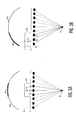
- FIGURE 1a shows the transmit beam profile 10 at a constant level below the intensity peak at the center of the beam, transmitted by and extending from a transducer array 8 that transmitted the beam.
- the transmit beam profile level is chosen by the designer and may be 3 dB, 6 dB, 20 dB, or some other level below the maximum intensity at the center of the beam.
- the beam profile is seen to be focused about a focal point 12 at the narrowest width of the beam profile by conventional transmit focusing.
- An orthogonal view of the beam 20 is shown below the transducer array 8 which is seen to comprise a center lobe 20a and side lobes on either side of the main lobe 20a.
- the transmitted beam reaches its tightest focus at the focal region 12 and diverges thereafter. In other implementations a diverging transmit beam may be used.
- the transmit beam 10, 20 is transmitted with a width that encompasses multiple receive lines 14, 16, and 18. Generally a wider beam is produced by transmitting from a smaller transmit aperture. That is, a lesser number of elements of the array 8 are actuated to transmit the beam than the total number of elements across the array. Following transmission echoes are received and focused along three receive line locations 14, 16 and 18. As discussed below, the echoes received by the transducer elements of the receive aperture are delayed and summed in three different ways to form multiple lines at different line locations 14, 16, and 18 in response to one transmit beam. In this example receive line 14 is received down the center of the transmit beam 10, 20 and receive lines 14 and 18 are laterally steered and focused to be received on either side of the center line.
- the outer lines 14 and 18 are within the transmit beam profile 10. In these regions the outer lines 14 and 18 are received from transmit energy on either side of the center line position thereby sampling targets in the image field on both sides of the center line position, thereby efficiently using the laterally spread energy of the transmit beam in the near and far fields for image reception and resolution.
- a second beam has been transmitted by shifting the transmit aperture to the right by the spacing of one receive line.
- the second transmit beam has the same beam profile as the first transmit beam and is outlined by beam profile curves 10'.
- three receive lines are simultaneously received and beamformed in response to the second transmission at receive line locations 16', 18' and 22.
- receive line 16' is aligned with receive line 16 from the first transmission
- receive line 18' is aligned with receive line 18 from the first transmission
- receive line 22 is located to the right of the center line 18' of the second transmission.
- the second set of receive multilines 16', 18', and 22 is saved for subsequent processing.
- FIGURE 1c a third beam has been transmitted from a center aperture location which is again shifted to the right by one receive line.
- This transmit beam is outlined by beam profile 10" and the transmission is followed by the simultaneous reception of three receive lines 18", 22' and 24.
- These three receive lines like the previous receive lines, are wholly or partially within the beam profile of their transmit beam with the same spacing as the lines of the preceding beams.
- receive line 18" is axially aligned with receive line 18' of the second transmission and receive line 18 of the first transmission
- receive line 22' is axially aligned with receive line 22 of the second transmission.
- the targets in the path of receive lines 18, 18' and 18" have now been sampled by three receive lines, each by a respectively different transmit beam.
- the beam profile for the transmit beam which converges on this focal point and diverges thereafter is defined by lines 31-34.
- a transmit beam will take a known amount of time at the speed of sound to converge at the focal point F 1 .
- an amount of time tp is required for the wavefront to insonify a point P in the image field. With the speed of sound in the medium being known, the time tp and the total transmit time can be calculated.
- FIGURE 2B a number of transmit beams have been transmitted from the transducer array 8 which have focal points shown as F 1 -F 4 .
- the beam profiles for these transmit beams are also delineated in FIGURE 2B . It is seen in this example that the point P is insonified (in the beam profiles) by the beams focused at focal points F 1 -F 3 , but is not insonified by the fourth beam focused at focal point F 4 , as the point P is outside of the beam profile 35-38 of this fourth beam.
- the contributions of the echoes from the first three transmit beams which insonify point P can be coherently combined to produce an effective focused signal at point P as shown in FIGURE 2c .
- the times required for a wavefront to travel from each virtual transducer focal point F 1 , F 2 , and F 3 to insonify point P can be calculated, then equalized with delays so that the echoes are coherently constructively combined to form the effective signal focused at and returned from point P.
- FIGURE 2B illustrates, such echoes from transmit focusing can be found along an entire receive line L.
- the delay profile 40 needed to focus signals from a full aperture F 1 -F n at point P is illustrated in FIGURE 2D .
- the delay is greatest in the center of the aperture where the transit time to point P is the shortest, and is the least at the sides of the aperture where the transit time to point P is the longest.
- the center focal point was assumed to need no delay, which means that the delays for the focal points lateral to the center are negative delays taken from earlier points in time of the received signals.
- this retrospective transmit focusing technique is used to create echo signals from a point in the image field as if it were insonified from different look directions.
- Different apertures are used for the different look directions which give the created signals speckle components which are relatively decorrelated for the different look directions such that, when the echo signals are combined, the overall image speckle is reduced.
- FIGURE 3A which is similar to FIGURE 2D , an aperture for a given look direction is selected by apodization.
- the apodization function 50 is a square wave having a value of one around the central elements of the transducer array and zero at other locations of the array.
- the central apodization function 50 causes the signals of the sub-aperture of the (virtual) transducer element focal points F x , F y , and F z to be used to form a signal at point P. These signals are delayed by the highlighted portion 42 of the delay profile 40, producing a signal for point P as if the point P were insonified by a transmit beam transmitted normal to the plane of the transducer elements, a transmit beam angle ⁇ 2 indicated by the arrow in FIGURE 3A .
- FIGURE 3B is similar to FIGURE 3A except that the apodization function 50 has moved to the left side of the transducer aperture to select a sub-aperture at the left for formation of an echo signal at point P.
- this sub-aperture is chosen a signal is produced as if the point P were being interrogated from a look direction at the left side of the array.
- the signals of the (virtual) transducer elements F A , F B , and F C at the left side of the array are selected by the weighting function 50 and delayed by delays indicated by the highlighted portion 44 of the delay profile 40.
- the combined signals produce an echo equivalent to insonifying point P from a look direction steered from left to right at an angle ⁇ 1 as indicated by the arrow in the drawing.
- the beam steering caused by the different delays for the different sub-apertures results in signals for point P with decorrelated speckle characteristics in the two samples.
- retrospective beam steering described above can be used for other purposes such as the production of a steered linear image.
- a typical operating sequence is as follows.
- a series of laterally displaced beams are transmitted from a transducer array. Generally these beams will be transmitted normal to the plane of the array (direction ⁇ 2 ).
- a multiline beamformer receives multiple beams at different lateral locations. In some implementations different steering angles can be used for the received beams.
- the received signals are delayed and combined to form received multilines which are focused over a considerable depth of field by retrospective transmit focusing as described in our previously filed patent application.
- the retrospective transmit focusing delays may be separate delays or may be included in the multiline beamformer delays.
- Groups of the received signals are weighted and coherently combined, which effects a retrospective apodization and steering of the transmit beam. Each group of signals is for a different sub-aperture for a particular look direction.
- the combined signals are detected, generally with log compression for the desired contrast resolution, and detected signals from different look directions for a common point are combined to form image points for a displayed image.
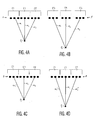
- FIGURES 4A-4D The use of different apertures can produce different beam steering directions (different look directions) as illustrated in FIGURES 4A-4D .
- three different steering directions, ⁇ 1 , ⁇ 2 , and ⁇ 3 are used to insonify a point at a shallow depth P S from the array of virtual transducers (focus depth) in the image field.
- Each beam emanates from a different sub-aperture of the array of virtual transducers as chosen by a different apodization function 51, 53, and 55.
- FIGURE 4B the same three steering directions are used for a point P D at a deeper depth of the image field.
- different sub-apertures must be used as indicated by the apodization functions 52, 54, and 56 which choose the different sub-apertures.
- These sub-apertures must use virtual transducer elements at different locations and/or distributions in order to maintain the same set of look directions at the different depths.
- the sub-apertures will expand dynamically with depth as is customary in ultrasound array systems.
- FIGURES 4C and 4D the same apertures are used at both the shallow depth of point P S and the deeper depth of point P D . While the orthogonal angle is readily produced ( ⁇ 2 ), the geometry of the same apertures 51, 53, 55 at the deeper depth results in the other two angles ⁇ 1 ' and ⁇ 3 ' being less steep. The effect on speckle reduction by the use of these slightly different look directions at different depths will not be noticeable in most implementations.
- An embodiment of FIGURES 4C-4D is beneficial near the edge of an image where the number of multilines available for retrospective focusing is limited.
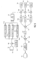
- FIGURE 5 illustrates in block diagram form an ultrasonic imaging system constructed in accordance with the principles of the present invention.
- An ultrasonic probe 102 includes a transducer array 104 of transducer elements. Selected groups of the transducer elements are actuated at respectively delayed times by the transmit beamformer 106 to transmit beams focused at selected focal regions in the desired directions and from the desired origin(s) along the array.
- the transmit beamformer is coupled to the transducer elements by a transmit/receive switch which may comprise a crosspoint switch that protects the receiver inputs from the high voltage transmit pulses applied.
- the echoes received by each transducer element of the array 104 in response to each transmit beam are applied to the inputs of multiline processors 110a-110n.
- Each multiline processor comprises a receive beamformer which applies its own set of delays and, if desired, apodization weights to weight the received echoes from the array elements to form a differently steered receive beam from the same transmit beam.
- Suitable multiline beamformers for the multiline processors 110a-110n may be found, for instance, in US Pat. 6,695,783 (Henderson et al. ) and US Pat. 5,318,033 (Savord ).
- the outputs of the multiline processors 110a-110n are coupled to a line store 112 which stores the received multilines at least until all of the multilines needed to form a line of display data have been acquired.
- the group of multilines used to form a particular line of display data are applied to respective ones of multipliers 116a-116n to produce the display data for the corresponding line location.
- the echo data from each line may, if desired be weighted by apodization weights 114a-114n. In general, these weights will weight each line as a function of its transmit impulse response.
- Let X be the azimuth of the receive line with respect to the transmit beam axis.
- the functions amplitude(X,Z) and propagation_time(X,Z) may, for example, be obtained from a simulation of the transmit field.
- An appropriate way to compute the propagation time is to use the phase delay of the field from monochromatic simulation at several frequencies.
- the amplitude may be computed by averaging the amplitude of the field at several frequencies.
- a depth-dependent normalization can be applied to the weights. This multiplies all the weights at a given depth by a common factor. For example, the normalization can be chosen so that speckle regions have uniform brightness with depth. By varying the weights as a function of depth, it is possible to vary the size and shape (apodization) of the aperture dynamically with depth.
- a dynamic focusing is obtained, but no steering is achieved.
- a first possibility is to use the propagation time and amplitude of the full transmit together with a sub-aperture selector, so that the delays and weights are applied only to the virtual transducers that are used for a given steering direction, as shown in Fig.3 .
- the effect of the sub-aperture selector is to apply a weight equal to zero to the virtual transducers that are not contributing to the beam.
- the sub-aperture is varying with the depth.
- Another possibility is to simulate the field generated by a sub-aperture of the physical array. For example, assume that the signals for three steering directions have to be generated. Then, the full transmit aperture can be divided into three sub-apertures, and the field can be simulated for each of the three sub-apertures. The amplitude and the propagation time of the wave-fronts is used for the delays and weights of the corresponding steering directions. In this case, the sub-aperture selector is no longer necessary, as its function is carried out by the weights.
- the amplitude and propagation time do not need to be derived from a simulation of the exact transmit characteristics used in the system.
- the designer may choose to use a different aperture size or a different apodization for example.
- the echoes from each line are weighted by the multipliers 116a-116n and delayed by delay lines 118a-118n.
- these delays will be related to the location of the transmit beam center to the receive line location as shown above.
- the delays are used to equalize the phase shift variance that exists from line to line for the multilines with differing transmit-receive beam location combinations, so that signal cancellation will not be caused by phase differences of the combined signals.
- the delay lines may be effected by storing the weighted multiline echo data in memory and reading the data out at later times which effect the necessary delay. Shift registers of differing lengths and clock signals may also be used to effect a digital delay, or an interpolating beamformer such as that described in the aforementioned US Pat. 6,695,783 may be used.
- the delayed signals are combined by a summer 120 and the resultant signals are coupled to an image processor 122.
- the image processor may perform scan conversion or other processing to improve the displayed image.
- the resultant image is displayed on an image display 124.
- the delay lines 118 and summer 120 effect a refocusing of the signals received from the several receive multilines which are co-aligned in a given direction.
- the refocusing adjusts for the phase differences resulting from the use of different transmit beam locations for each multiline, preventing undesired phase cancellation in the combined signals.
- the weights 114 weight the contributions of the multilines in relation to the proximity of the transmit beam to the multiline location, giving higher weight to receive beams with higher signal-to-noise ratios. This results in an extended depth of field along each receive line and an enhanced penetration (improved signal-to-noise ratio) due to the combination of multiple samplings in each receive line direction.
- This processing which interpolates multiple received signals, will effect a transmit refocusing of the echo signals for a beam steered normal to the plane of the transducer array 104 as described in our pending patent application.
- both a steering direction and focusing in the selected direction are provided by the delay lines 118.
- the sub-aperture for the steered beam must also be chosen as described in conjunction with FIGURE 4 .
- the sub-aperture is chosen by the apodizing weights 114 which accentuate the signals of the desired sub-aperture while attenuating or omitting signals from other regions of the array.
- weights 114 in FIGURE 5 select the sub-aperture of the steered beam and the delay lines 118 impart the necessary steering and focusing delay.
- the delayed signals are then combined by the summer 120 to form the retrospectively steered transmit beam.
- the coherent echo signals for the steered beam are then detected by a detector 130 to form the beam for look direction 1 (LD 2 ).
- the same sub-aperture selection processing and steering is performed for the other look directions, LD 1 and LD 3 in this example.
- the signals are combined by a summer 140 to form the speckle-reduced signal.
- the image data is processed by an image processor 122 which performs functions such as scan conversion to the desired image format, and the image is displayed on a display 124.
- the function of FIGURE 5 may be performed in other sequences if desired in a particular implementation. For instance, the detected signals of each look direction may be scan converted, then the scan converted signal data combined by the summer 140.
- the different look directions can be employed on transmit, on receive, or both.
- the foregoing processing effects different transmit look directions through retrospective steering of beams originally transmitted normal to the plane of the transducer array.
- Receive look direction diversity may be implemented in several ways. One is to actually steer the beams on receive by choosing the appropriate delay profile and apodization employed by the multiline processors. The initial transmit beams are transmitted normal to the plane of the array and on receive the receive beams are steered in different directions as is known in the art. Alternatively, receive steering may be applied retrospectively. After the transmit beams are transmitted normal to the array the multilines are received in the same direction.
- FIGURE 6A illustrates an exemplary delay profile applied to multilines which are received normal to the array.
- the profile curve 80 is defined for the first few transmits only, indicating that it is for the leftmost sub-aperture of the array of virtual transducers.
- FIGURE 6B illustrates a delay profile 90 for multilines which have been steered on receive. The slope of the delay curve 90 indicates the substantially linear steering term of these delays.
- the transmitted beams do not have to be transmitted normal to the plane of the array but may be transmitted at an acute angle such as one of the other steering angles.
- the different sub-apertures do not have to be entirely distinct In other implementations a small number of received multilines can be increased by interpolating additional intermediate multilines, then performing the inventive processing with the increased number of multilines.
- the sub-aperture selection and beam steering delay can be implemented separately or composited with the apodization and delays of the multiline processors.
- the steered beams can be put to other uses, such as steering at only the lateral sides of a 2D image to form a trapezoidal image format.
- An implementation of the present invention can provide superior motion artifact immunity compared to standard spatial compounding, as only a single scan of the image field is needed to form the different steering directions. The time of the scan to produce the data needed for an image, and consequently motion artifacts, are reduced.
Landscapes
- Engineering & Computer Science (AREA)
- Physics & Mathematics (AREA)
- Radar, Positioning & Navigation (AREA)
- Remote Sensing (AREA)
- Computer Networks & Wireless Communication (AREA)
- General Physics & Mathematics (AREA)
- Acoustics & Sound (AREA)
- Multimedia (AREA)
- Ultra Sonic Daignosis Equipment (AREA)
Claims (10)
- Système d'imagerie diagnostique ultrasonique, comprenant :une sonde (102) comprenant un réseau d'éléments transducteurs (8, 104) possédant une ouverture ;un formeur de faisceau de transmission (106), couplé au réseau d'éléments transducteurs (8, 104), et configuré pour transmettre, dans une direction donnée, à des instants respectivement retardés, une pluralité de faisceaux de transmission concentrés (10, 10', 10") qui sont latéralement déplacés à travers l'ouverture du réseau (8, 104) ;un formeur de faisceau de réception à lignes multiples (110a-110n), couplé au réseau d'éléments transducteurs (8, 104), pour recevoir de multiples signaux d'écho à différents emplacements latéraux du réseau d'éléments transducteurs (8, 104) et pour produire une pluralité de lignes de réception aux différents emplacements latéraux en réponse à chaque faisceau de transmission (10, 10', 10") ;un sélecteur de sous-ouverture (114) couplé au formeur de faisceau de réception à lignes multiples (110a-110n) pour sélectionner différentes sous-ouvertures pour différentes directions de vision (LD1, LD2, LD3);caractérisé en ce que le système d'imagerie diagnostique ultrasonique comprend en outre :un circuit d'orientation qui comprend une pluralité de retards (118a-118n) pour retarder les signaux d'écho de différents événements de transmission à chaque ligne de réception et produire des signaux retardés, et un sommateur (120) pour combiner les signaux retardés pour former des faisceaux orientés rétrospectivement, dans lequel un faisceau orienté rétrospectivement d'une sous-ouverture sélectionnée est orienté au moyen des retards (118a-118n) dans une différente direction de vision (LD1, LD2, LD3) par rapport à des faisceaux d'autres sous-ouvertures pour créer des échos reçus à partir de différentes directions de vision, à partir de chacun parmi une pluralité de différents points dans le champ d'image ;un détecteur (130) pour détecter les échos reçus de chacun des faisceaux orientés pour former des signaux de faisceau ;un circuit combinateur (140) pour combiner les signaux de faisceau détectés des différentes directions de vision (LD1, LD2, LD3) pour un point particulier (P) dans le champ d'image pour former des signaux à chatoiement réduit ; etun affichage (124) couplé au circuit combinateur (140) qui produit une image avec chatoiement réduit à partir des signaux à chatoiement réduit.
- Système d'imagerie diagnostique ultrasonique selon la revendication 1, dans lequel le sélecteur de sous-ouvertures (114) comprend en outre un circuit d'apodisation.
- Système d'imagerie diagnostique ultrasonique selon la revendication 2, dans lequel le circuit d'apodisation comprend en outre un circuit de pondération.
- Système d'imagerie diagnostique ultrasonique selon la revendication 1, dans lequel le détecteur (130) comprend en outre un détecteur d'amplitude.
- Procédé pour produire des images à ultrasons avec artéfact à chatoiement réduit, comprenant :la transmission, à des instants respectivement retardés, d'une pluralité de faisceaux de transmission concentrés (10, 10', 10") dans une direction donnée à partir d'un transducteur de réseau (8, 104) sur un champ d'image ;la réception de multiples signaux d'écho à différents emplacements latéraux du transducteur de réseau (8, 104) et la production d'une pluralité de lignes de réception aux différents emplacements latéraux en réponse à chaque faisceau de transmission (10, 10', 10");la sélection de différentes sous-ouvertures pour différentes directions de vision (LD1, LD2, LD3);caractérisé par les étapes de :le retardement des signaux d'écho de différents événements de transmission à chaque ligne de réception et la production de signaux retardés ;la combinaison des signaux retardés pour former rétrospectivement des faisceaux orientés, dans lequel un faisceau orienté rétrospectivement d'une sous-ouverture sélectionnée est orientée au moyen des retards dans une différente direction de vision (LD1, LD2, LD3) par rapport à des faisceaux d'autres sous-ouvertures pour créer des échos reçus à partir de différentes directions de vision, à partir de chacun parmi une pluralité de différents points dans le champ d'image ;la détection des échos reçus de chaque des faisceaux orientés pour former des signaux de faisceau ;la combinaison des signaux de faisceau détectés des différentes directions de vision (LD1, LD2, LD3) pour un point particulier (P) dans le champ d'image pour former des signaux à chatoiement réduit ; etla production d'une image avec chatoiement réduit à partir des signaux à chatoiement réduit.
- Procédé selon la revendication 5, comprenant en outre l'affichage de l'image.
- Procédé selon la revendication 5, dans lequel les différentes sous-ouvertures sont définies, comprenant l'apodisation des signaux d'écho à lignes multiples reçus.
- Procédé selon la revendication 5, dans lequel la direction donnée comprend en outre la direction qui est normale au plan du réseau de transducteurs (8, 104), dans lequel une parmi la pluralité de directions de vision (LD1, LD2, LD3) est la direction donnée.
- Procédé selon la revendication 8, dans lequel la réception d'une pluralité de lignes multiples de signaux d'écho comprend en outre la réception d'une pluralité de lignes multiples de signaux d'écho dans la direction donnée.
- Procédé selon la revendication 8, dans lequel la réception d'une pluralité de lignes multiples de signaux d'écho comprend en outre la réception d'une pluralité de lignes multiples de signaux d'écho orientées dans la pluralité de directions de vision (LD1, LD2, LD3).
Applications Claiming Priority (3)
| Application Number | Priority Date | Filing Date | Title |
|---|---|---|---|
| US74714806P | 2006-05-12 | 2006-05-12 | |
| US91134307P | 2007-04-12 | 2007-04-12 | |
| PCT/US2007/066758 WO2007133882A2 (fr) | 2006-05-12 | 2007-04-17 | Focalisation de transmission dynamique retrospective destinée à une combinaison spatiale |
Publications (3)
| Publication Number | Publication Date |
|---|---|
| EP2019600A2 EP2019600A2 (fr) | 2009-02-04 |
| EP2019600A4 EP2019600A4 (fr) | 2012-03-28 |
| EP2019600B1 true EP2019600B1 (fr) | 2015-09-16 |
Family
ID=38694587
Family Applications (1)
| Application Number | Title | Priority Date | Filing Date |
|---|---|---|---|
| EP07760755.4A Active EP2019600B1 (fr) | 2006-05-12 | 2007-04-17 | Focalisation de transmission dynamique retrospective destinée à une combinaison spatiale |
Country Status (4)
| Country | Link |
|---|---|
| US (1) | US8317712B2 (fr) |
| EP (1) | EP2019600B1 (fr) |
| JP (1) | JP5238692B2 (fr) |
| WO (1) | WO2007133882A2 (fr) |
Families Citing this family (41)
| Publication number | Priority date | Publication date | Assignee | Title |
|---|---|---|---|---|
| JP4975098B2 (ja) * | 2006-05-12 | 2012-07-11 | コーニンクレッカ フィリップス エレクトロニクス エヌ ヴィ | 動き補償による超音波合成送信フォーカシング |
| JP4717109B2 (ja) * | 2008-12-04 | 2011-07-06 | 日立アロカメディカル株式会社 | 超音波診断装置 |
| JP5789195B2 (ja) | 2008-12-08 | 2015-10-07 | シリコンバレー メディカル インスツルメンツ インコーポレイテッド | 画像誘導のためのカテーテルのシステム |
| JP5306919B2 (ja) * | 2009-06-26 | 2013-10-02 | 一般財団法人電力中央研究所 | 超音波探傷法及び装置 |
| EP2453800B1 (fr) | 2009-07-17 | 2018-11-21 | Koninklijke Philips N.V. | Échantillonnage précis dans l'espace par vibrométrie ultrasonore à dispersion des ondes de cisaillement |
| CN102869308B (zh) | 2010-05-03 | 2015-04-29 | 皇家飞利浦电子股份有限公司 | 用于对介入工具上的(一个或多个)超声换能器进行超声跟踪的设备和方法 |
| US20130258805A1 (en) * | 2010-10-11 | 2013-10-03 | B-K Medical Aps | Methods and systems for producing compounded ultrasound images |
| WO2012085812A2 (fr) | 2010-12-22 | 2012-06-28 | Koninklijke Philips Electronics N.V. | Estimation de vitesse d'onde de cisaillement à l'aide d'un centre de masse |
| CA2834993C (fr) * | 2011-05-02 | 2019-04-30 | Verasonics, Inc. | Formation d'images ultrasonores amelioree a l'aide de regions qualifiees de faisceaux d'emission se chevauchant |
| WO2012172458A1 (fr) * | 2011-06-13 | 2012-12-20 | Koninklijke Philips Electronics N.V. | Localisation d'aiguille tridimensionnelle au moyen d'une sonde d'imagerie bidimensionnelle |
| WO2013116809A1 (fr) * | 2012-02-03 | 2013-08-08 | Los Alamos National Security, Llc | Tomographie à forme d'onde ultrasonore à régularisation par variation totale |
| WO2013116783A1 (fr) | 2012-02-03 | 2013-08-08 | Los Alamos National Security, Llc | Technique musicale à réversibilité dans le temps et à fenêtre pour imagerie par ultrasons super résolution |
| US8568079B2 (en) | 2012-02-15 | 2013-10-29 | Cascade Corporation | Rotator braking system for a lift truck load handler |
| KR101356616B1 (ko) | 2012-02-17 | 2014-02-04 | 알피니언메디칼시스템 주식회사 | 가중치 보간 방법 및 이를 이용한 초음파 진단장치 |
| JP5905856B2 (ja) * | 2012-07-13 | 2016-04-20 | 富士フイルム株式会社 | 超音波検査装置 |
| CN105050505B (zh) | 2013-03-20 | 2019-01-29 | 皇家飞利浦有限公司 | 用于超声微钙化检测的波束形成技术 |
| US9366753B2 (en) | 2013-08-19 | 2016-06-14 | General Electric Company | Systems and methods for ultrasound retrospective transmit focus beamforming |
| CN106456118B (zh) * | 2013-11-19 | 2019-12-31 | 港大科桥有限公司 | 超声流体向量成像装置及其方法 |
| JP2016539707A (ja) | 2013-12-09 | 2016-12-22 | コーニンクレッカ フィリップス エヌ ヴェKoninklijke Philips N.V. | 画像情報に基づく画像合成 |
| US9713456B2 (en) | 2013-12-30 | 2017-07-25 | Acist Medical Systems, Inc. | Position sensing in intravascular imaging |
| US10064602B2 (en) * | 2014-06-03 | 2018-09-04 | Siemens Medical Solutions Usa, Inc. | Coherence ultrasound imaging with broad transmit beams |
| WO2016017331A1 (fr) | 2014-07-31 | 2016-02-04 | 富士フイルム株式会社 | Dispositif de diagnostic utilisant des ondes acoustiques et procédé de commande associé |
| US11026655B2 (en) * | 2014-09-26 | 2021-06-08 | Samsung Electronics Co., Ltd. | Ultrasound diagnostic apparatus and method of generating B-flow ultrasound image with single transmission and reception event |
| JP6406019B2 (ja) * | 2015-01-09 | 2018-10-17 | コニカミノルタ株式会社 | 超音波信号処理装置、及び超音波診断装置 |
| US11112500B2 (en) * | 2015-03-02 | 2021-09-07 | Bk Medical Aps | Ultrasound imaging flow vector velocity estimation with directional transverse oscillation |
| JP6741012B2 (ja) * | 2015-10-08 | 2020-08-19 | コニカミノルタ株式会社 | 超音波診断装置、及び超音波信号処理方法 |
| US11432793B2 (en) * | 2015-12-28 | 2022-09-06 | Bk Medical Aps | High resolution compound ultrasound flow imaging |
| JP6963567B2 (ja) | 2016-05-19 | 2021-11-10 | アシスト・メディカル・システムズ,インコーポレイテッド | 血管内プロセスにおける位置検知 |
| JP6943883B2 (ja) | 2016-05-19 | 2021-10-06 | アシスト・メディカル・システムズ,インコーポレイテッド | 血管内プロセスにおける位置検知 |
| EP3475727B1 (fr) | 2016-06-23 | 2021-11-03 | Koninklijke Philips N.V. | Imagerie ultrasonore à foyer synthétique rapide avec de grands réseaux linéaires |
| WO2017220354A1 (fr) | 2016-06-23 | 2017-12-28 | Koninklijke Philips N.V. | Imagerie ultrasonore à focalisation synthétique rapide à grands réseaux linéaires |
| EP3263036B1 (fr) | 2016-06-30 | 2024-10-02 | Esaote S.p.A. | Procédé et système pour effectuer une transmission dynamique retrospective en se focalisant sur la formation de faisceau sur des signaux ultrasonores |
| JP6747108B2 (ja) * | 2016-07-05 | 2020-08-26 | コニカミノルタ株式会社 | 超音波信号処理装置、超音波信号処理方法、及び、超音波診断装置 |
| JP7231541B2 (ja) * | 2016-11-14 | 2023-03-01 | コーニンクレッカ フィリップス エヌ ヴェ | 解剖学的、機能的及び血行動態イメージングのためのトリプルモード超音波イメージング |
| CN110622034B (zh) | 2017-05-11 | 2023-10-20 | 皇家飞利浦有限公司 | 超声诊断图像中的混响伪影消除 |
| US11583254B2 (en) | 2017-06-28 | 2023-02-21 | Duke University | Systems and methods for intra-beam compounding for ultrasound imaging |
| US11690595B2 (en) | 2018-04-09 | 2023-07-04 | BFLY Operations, Inc | Methods and apparatuses for offloading ultrasound data |
| EP3794371B1 (fr) | 2018-05-15 | 2025-10-15 | Koninklijke Philips N.V. | Système ultrasonore de focalisation de transmission synthétique à correction d'aberration de vitesse du son |
| CN110101411B (zh) * | 2019-05-28 | 2020-11-10 | 飞依诺科技(苏州)有限公司 | 超声成像空间复合方法及系统 |
| WO2022117393A1 (fr) * | 2020-12-01 | 2022-06-09 | Koninklijke Philips N.V. | Focalisation rétrospective d'émission à l'aide de systèmes, de dispositifs et de procédés de vitesse d'émission |
| WO2022238218A1 (fr) | 2021-05-10 | 2022-11-17 | Koninklijke Philips N.V. | Génération d'image ultrasonore composée de manière cohérente et systèmes, procédés et dispositifs associés |
Family Cites Families (19)
| Publication number | Priority date | Publication date | Assignee | Title |
|---|---|---|---|---|
| US4644795A (en) | 1985-07-29 | 1987-02-24 | Advanced Technology Laboratories, Inc. | High resolution multiline ultrasonic beamformer |
| JP2777197B2 (ja) * | 1989-06-13 | 1998-07-16 | 株式会社東芝 | 超音波診断装置 |
| US5318033A (en) | 1992-04-17 | 1994-06-07 | Hewlett-Packard Company | Method and apparatus for increasing the frame rate and resolution of a phased array imaging system |
| US5793701A (en) * | 1995-04-07 | 1998-08-11 | Acuson Corporation | Method and apparatus for coherent image formation |
| US5564424A (en) * | 1995-06-30 | 1996-10-15 | Siemens Medical Systems, Inc. | Method and apparatus for pulsed doppler ultrasound beam-forming |
| US5647365A (en) * | 1995-11-13 | 1997-07-15 | Siemens Medical Systems, Inc. | Apodization parameter generator for ultrasound medical imaging system |
| JPH10118063A (ja) * | 1996-10-24 | 1998-05-12 | Aloka Co Ltd | 超音波診断装置 |
| JP3763924B2 (ja) * | 1997-03-17 | 2006-04-05 | フクダ電子株式会社 | 超音波診断装置 |
| KR100280197B1 (ko) * | 1997-11-10 | 2001-02-01 | 이민화 | 초음파영상화시스템의초음파신호집속방법및장치 |
| US6066099A (en) * | 1998-11-23 | 2000-05-23 | General Electric Company | Method and apparatus for high-frame-rate high-resolution ultrasonic image data acquisition |
| US6464638B1 (en) * | 2000-10-05 | 2002-10-15 | Koninklijke Philips Electronics N.V. | Ultrasound imaging system and method for spatial compounding |
| US6695783B2 (en) * | 2000-12-22 | 2004-02-24 | Koninklijke Philips Electronics N.V. | Multiline ultrasound beamformers |
| US6508770B1 (en) * | 2001-03-08 | 2003-01-21 | Acuson Corporation | Aperture compounding for medical imaging |
| US6482157B2 (en) | 2001-03-30 | 2002-11-19 | Koninklijke Philips Electronics N.V. | Ultrasonic diagnostic imaging systems with blended multiline for 2D and 3D applications |
| US6743174B2 (en) * | 2002-04-01 | 2004-06-01 | Koninklijke Philips Electronics N.V. | Ultrasonic diagnostic imaging system with automatically controlled contrast and brightness |
| US7347820B2 (en) * | 2002-11-06 | 2008-03-25 | Koninklijke Philips Electronics N.V. | Phased array acoustic system for 3D imaging of moving parts |
| US6589177B1 (en) | 2002-11-15 | 2003-07-08 | Koninklijke Philips Electronics N.V. | Method and apparatus for obtaining B-flow and B-mode data from multiline beams in an ultrasound imaging system |
| JP4584927B2 (ja) * | 2003-09-10 | 2010-11-24 | コーニンクレッカ フィリップス エレクトロニクス エヌ ヴィ | 複数ビームが同時送信される、超音波の空間的コンパウンド |
| JP4625663B2 (ja) * | 2004-08-18 | 2011-02-02 | 株式会社東芝 | 超音波診断装置 |
-
2007
- 2007-04-17 US US12/299,639 patent/US8317712B2/en active Active
- 2007-04-17 EP EP07760755.4A patent/EP2019600B1/fr active Active
- 2007-04-17 JP JP2009509924A patent/JP5238692B2/ja active Active
- 2007-04-17 WO PCT/US2007/066758 patent/WO2007133882A2/fr not_active Ceased
Also Published As
| Publication number | Publication date |
|---|---|
| WO2007133882A2 (fr) | 2007-11-22 |
| EP2019600A4 (fr) | 2012-03-28 |
| JP2009536856A (ja) | 2009-10-22 |
| WO2007133882A3 (fr) | 2008-11-20 |
| EP2019600A2 (fr) | 2009-02-04 |
| JP5238692B2 (ja) | 2013-07-17 |
| US8317712B2 (en) | 2012-11-27 |
| US20090069693A1 (en) | 2009-03-12 |
Similar Documents
| Publication | Publication Date | Title |
|---|---|---|
| US8317712B2 (en) | Retrospective dynamic transmit focusing for spatial compounding | |
| EP2019626B1 (fr) | Mise au point de transmission dynamique rétrospective incohérente | |
| US9345455B2 (en) | Ultrasonic synthetic transmit focusing with motion compensation | |
| US20050148874A1 (en) | Ultrasonic imaging aberration correction with microbeamforming | |
| US11199625B2 (en) | Rapid synthetic focus ultrasonic imaging with large linear arrays | |
| JP2009536853A5 (fr) | ||
| US20040054285A1 (en) | Elevation compounding for ultrasound imaging | |
| EP3794371A1 (fr) | Système ultrasonore de focalisation de transmission synthétique à correction d'aberration de vitesse du son | |
| WO2017220354A1 (fr) | Imagerie ultrasonore à focalisation synthétique rapide à grands réseaux linéaires |
Legal Events
| Date | Code | Title | Description |
|---|---|---|---|
| PUAI | Public reference made under article 153(3) epc to a published international application that has entered the european phase |
Free format text: ORIGINAL CODE: 0009012 |
|
| AK | Designated contracting states |
Kind code of ref document: A2 Designated state(s): AT BE BG CH CY CZ DE DK EE ES FI FR GB GR HU IE IS IT LI LT LU LV MC MT NL PL PT RO SE SI SK TR |
|
| AX | Request for extension of the european patent |
Extension state: AL BA HR MK RS |
|
| RIC1 | Information provided on ipc code assigned before grant |
Ipc: A61B 8/00 20060101AFI20090409BHEP |
|
| 17P | Request for examination filed |
Effective date: 20090520 |
|
| RBV | Designated contracting states (corrected) |
Designated state(s): AT BE BG CH CY CZ DE DK EE ES FI FR GB GR HU IE IS IT LI LT LU LV MC MT NL PL PT RO SE SI SK TR |
|
| DAX | Request for extension of the european patent (deleted) | ||
| A4 | Supplementary search report drawn up and despatched |
Effective date: 20120224 |
|
| RIC1 | Information provided on ipc code assigned before grant |
Ipc: G01S 15/89 20060101ALI20120220BHEP Ipc: A61B 8/00 20060101AFI20120220BHEP Ipc: G01S 7/52 20060101ALI20120220BHEP |
|
| 17Q | First examination report despatched |
Effective date: 20121031 |
|
| REG | Reference to a national code |
Ref country code: DE Ref legal event code: R079 Ref document number: 602007043155 Country of ref document: DE Free format text: PREVIOUS MAIN CLASS: A41G0003000000 Ipc: G10K0011340000 |
|
| GRAP | Despatch of communication of intention to grant a patent |
Free format text: ORIGINAL CODE: EPIDOSNIGR1 |
|
| INTG | Intention to grant announced |
Effective date: 20150407 |
|
| RIC1 | Information provided on ipc code assigned before grant |
Ipc: G10K 11/34 20060101AFI20150323BHEP Ipc: G01S 15/89 20060101ALI20150323BHEP Ipc: G01S 7/52 20060101ALI20150323BHEP |
|
| GRAS | Grant fee paid |
Free format text: ORIGINAL CODE: EPIDOSNIGR3 |
|
| GRAA | (expected) grant |
Free format text: ORIGINAL CODE: 0009210 |
|
| AK | Designated contracting states |
Kind code of ref document: B1 Designated state(s): AT BE BG CH CY CZ DE DK EE ES FI FR GB GR HU IE IS IT LI LT LU LV MC MT NL PL PT RO SE SI SK TR |
|
| REG | Reference to a national code |
Ref country code: GB Ref legal event code: FG4D |
|
| REG | Reference to a national code |
Ref country code: CH Ref legal event code: EP |
|
| REG | Reference to a national code |
Ref country code: IE Ref legal event code: FG4D |
|
| REG | Reference to a national code |
Ref country code: AT Ref legal event code: REF Ref document number: 750342 Country of ref document: AT Kind code of ref document: T Effective date: 20151015 |
|
| REG | Reference to a national code |
Ref country code: DE Ref legal event code: R096 Ref document number: 602007043155 Country of ref document: DE |
|
| RAP2 | Party data changed (patent owner data changed or rights of a patent transferred) |
Owner name: KONINKLIJKE PHILIPS N.V. |
|
| REG | Reference to a national code |
Ref country code: GB Ref legal event code: 746 Effective date: 20151223 |
|
| REG | Reference to a national code |
Ref country code: NL Ref legal event code: MP Effective date: 20150916 |
|
| PG25 | Lapsed in a contracting state [announced via postgrant information from national office to epo] |
Ref country code: LT Free format text: LAPSE BECAUSE OF FAILURE TO SUBMIT A TRANSLATION OF THE DESCRIPTION OR TO PAY THE FEE WITHIN THE PRESCRIBED TIME-LIMIT Effective date: 20150916 Ref country code: GR Free format text: LAPSE BECAUSE OF FAILURE TO SUBMIT A TRANSLATION OF THE DESCRIPTION OR TO PAY THE FEE WITHIN THE PRESCRIBED TIME-LIMIT Effective date: 20151217 Ref country code: FI Free format text: LAPSE BECAUSE OF FAILURE TO SUBMIT A TRANSLATION OF THE DESCRIPTION OR TO PAY THE FEE WITHIN THE PRESCRIBED TIME-LIMIT Effective date: 20150916 Ref country code: LV Free format text: LAPSE BECAUSE OF FAILURE TO SUBMIT A TRANSLATION OF THE DESCRIPTION OR TO PAY THE FEE WITHIN THE PRESCRIBED TIME-LIMIT Effective date: 20150916 |
|
| REG | Reference to a national code |
Ref country code: LT Ref legal event code: MG4D |
|
| REG | Reference to a national code |
Ref country code: AT Ref legal event code: MK05 Ref document number: 750342 Country of ref document: AT Kind code of ref document: T Effective date: 20150916 |
|
| PG25 | Lapsed in a contracting state [announced via postgrant information from national office to epo] |
Ref country code: SE Free format text: LAPSE BECAUSE OF FAILURE TO SUBMIT A TRANSLATION OF THE DESCRIPTION OR TO PAY THE FEE WITHIN THE PRESCRIBED TIME-LIMIT Effective date: 20150916 |
|
| PG25 | Lapsed in a contracting state [announced via postgrant information from national office to epo] |
Ref country code: NL Free format text: LAPSE BECAUSE OF FAILURE TO SUBMIT A TRANSLATION OF THE DESCRIPTION OR TO PAY THE FEE WITHIN THE PRESCRIBED TIME-LIMIT Effective date: 20150916 |
|
| REG | Reference to a national code |
Ref country code: FR Ref legal event code: PLFP Year of fee payment: 10 |
|
| PG25 | Lapsed in a contracting state [announced via postgrant information from national office to epo] |
Ref country code: SK Free format text: LAPSE BECAUSE OF FAILURE TO SUBMIT A TRANSLATION OF THE DESCRIPTION OR TO PAY THE FEE WITHIN THE PRESCRIBED TIME-LIMIT Effective date: 20150916 Ref country code: EE Free format text: LAPSE BECAUSE OF FAILURE TO SUBMIT A TRANSLATION OF THE DESCRIPTION OR TO PAY THE FEE WITHIN THE PRESCRIBED TIME-LIMIT Effective date: 20150916 Ref country code: IS Free format text: LAPSE BECAUSE OF FAILURE TO SUBMIT A TRANSLATION OF THE DESCRIPTION OR TO PAY THE FEE WITHIN THE PRESCRIBED TIME-LIMIT Effective date: 20160116 Ref country code: CZ Free format text: LAPSE BECAUSE OF FAILURE TO SUBMIT A TRANSLATION OF THE DESCRIPTION OR TO PAY THE FEE WITHIN THE PRESCRIBED TIME-LIMIT Effective date: 20150916 Ref country code: ES Free format text: LAPSE BECAUSE OF FAILURE TO SUBMIT A TRANSLATION OF THE DESCRIPTION OR TO PAY THE FEE WITHIN THE PRESCRIBED TIME-LIMIT Effective date: 20150916 |
|
| PG25 | Lapsed in a contracting state [announced via postgrant information from national office to epo] |
Ref country code: PL Free format text: LAPSE BECAUSE OF FAILURE TO SUBMIT A TRANSLATION OF THE DESCRIPTION OR TO PAY THE FEE WITHIN THE PRESCRIBED TIME-LIMIT Effective date: 20150916 Ref country code: AT Free format text: LAPSE BECAUSE OF FAILURE TO SUBMIT A TRANSLATION OF THE DESCRIPTION OR TO PAY THE FEE WITHIN THE PRESCRIBED TIME-LIMIT Effective date: 20150916 Ref country code: RO Free format text: LAPSE BECAUSE OF FAILURE TO SUBMIT A TRANSLATION OF THE DESCRIPTION OR TO PAY THE FEE WITHIN THE PRESCRIBED TIME-LIMIT Effective date: 20150916 Ref country code: PT Free format text: LAPSE BECAUSE OF FAILURE TO SUBMIT A TRANSLATION OF THE DESCRIPTION OR TO PAY THE FEE WITHIN THE PRESCRIBED TIME-LIMIT Effective date: 20160118 |
|
| REG | Reference to a national code |
Ref country code: DE Ref legal event code: R097 Ref document number: 602007043155 Country of ref document: DE |
|
| PLBE | No opposition filed within time limit |
Free format text: ORIGINAL CODE: 0009261 |
|
| STAA | Information on the status of an ep patent application or granted ep patent |
Free format text: STATUS: NO OPPOSITION FILED WITHIN TIME LIMIT |
|
| 26N | No opposition filed |
Effective date: 20160617 |
|
| PG25 | Lapsed in a contracting state [announced via postgrant information from national office to epo] |
Ref country code: BE Free format text: LAPSE BECAUSE OF NON-PAYMENT OF DUE FEES Effective date: 20160430 Ref country code: DK Free format text: LAPSE BECAUSE OF FAILURE TO SUBMIT A TRANSLATION OF THE DESCRIPTION OR TO PAY THE FEE WITHIN THE PRESCRIBED TIME-LIMIT Effective date: 20150916 |
|
| PG25 | Lapsed in a contracting state [announced via postgrant information from national office to epo] |
Ref country code: SI Free format text: LAPSE BECAUSE OF FAILURE TO SUBMIT A TRANSLATION OF THE DESCRIPTION OR TO PAY THE FEE WITHIN THE PRESCRIBED TIME-LIMIT Effective date: 20150916 |
|
| REG | Reference to a national code |
Ref country code: CH Ref legal event code: PL |
|
| PG25 | Lapsed in a contracting state [announced via postgrant information from national office to epo] |
Ref country code: BE Free format text: LAPSE BECAUSE OF FAILURE TO SUBMIT A TRANSLATION OF THE DESCRIPTION OR TO PAY THE FEE WITHIN THE PRESCRIBED TIME-LIMIT Effective date: 20150916 Ref country code: LU Free format text: LAPSE BECAUSE OF FAILURE TO SUBMIT A TRANSLATION OF THE DESCRIPTION OR TO PAY THE FEE WITHIN THE PRESCRIBED TIME-LIMIT Effective date: 20160417 |
|
| REG | Reference to a national code |
Ref country code: IE Ref legal event code: MM4A |
|
| PG25 | Lapsed in a contracting state [announced via postgrant information from national office to epo] |
Ref country code: LI Free format text: LAPSE BECAUSE OF NON-PAYMENT OF DUE FEES Effective date: 20160430 Ref country code: CH Free format text: LAPSE BECAUSE OF NON-PAYMENT OF DUE FEES Effective date: 20160430 |
|
| REG | Reference to a national code |
Ref country code: FR Ref legal event code: PLFP Year of fee payment: 11 |
|
| PG25 | Lapsed in a contracting state [announced via postgrant information from national office to epo] |
Ref country code: IE Free format text: LAPSE BECAUSE OF NON-PAYMENT OF DUE FEES Effective date: 20160417 |
|
| REG | Reference to a national code |
Ref country code: FR Ref legal event code: PLFP Year of fee payment: 12 |
|
| PG25 | Lapsed in a contracting state [announced via postgrant information from national office to epo] |
Ref country code: HU Free format text: LAPSE BECAUSE OF FAILURE TO SUBMIT A TRANSLATION OF THE DESCRIPTION OR TO PAY THE FEE WITHIN THE PRESCRIBED TIME-LIMIT; INVALID AB INITIO Effective date: 20070417 Ref country code: CY Free format text: LAPSE BECAUSE OF FAILURE TO SUBMIT A TRANSLATION OF THE DESCRIPTION OR TO PAY THE FEE WITHIN THE PRESCRIBED TIME-LIMIT Effective date: 20150916 |
|
| PG25 | Lapsed in a contracting state [announced via postgrant information from national office to epo] |
Ref country code: TR Free format text: LAPSE BECAUSE OF FAILURE TO SUBMIT A TRANSLATION OF THE DESCRIPTION OR TO PAY THE FEE WITHIN THE PRESCRIBED TIME-LIMIT Effective date: 20150916 Ref country code: MT Free format text: LAPSE BECAUSE OF NON-PAYMENT OF DUE FEES Effective date: 20160430 Ref country code: MC Free format text: LAPSE BECAUSE OF FAILURE TO SUBMIT A TRANSLATION OF THE DESCRIPTION OR TO PAY THE FEE WITHIN THE PRESCRIBED TIME-LIMIT Effective date: 20150916 |
|
| PG25 | Lapsed in a contracting state [announced via postgrant information from national office to epo] |
Ref country code: BG Free format text: LAPSE BECAUSE OF FAILURE TO SUBMIT A TRANSLATION OF THE DESCRIPTION OR TO PAY THE FEE WITHIN THE PRESCRIBED TIME-LIMIT Effective date: 20150916 |
|
| REG | Reference to a national code |
Ref country code: DE Ref legal event code: R084 Ref document number: 602007043155 Country of ref document: DE |
|
| REG | Reference to a national code |
Ref country code: DE Ref legal event code: R082 Ref document number: 602007043155 Country of ref document: DE Representative=s name: MEISSNER BOLTE PATENTANWAELTE RECHTSANWAELTE P, DE Ref country code: DE Ref legal event code: R081 Ref document number: 602007043155 Country of ref document: DE Owner name: KONINKLIJKE PHILIPS N.V., NL Free format text: FORMER OWNER: KONINKLIJKE PHILIPS ELECTRONICS N.V., BOTHELL, WASH., US |
|
| PGFP | Annual fee paid to national office [announced via postgrant information from national office to epo] |
Ref country code: IT Payment date: 20220421 Year of fee payment: 16 Ref country code: FR Payment date: 20220427 Year of fee payment: 16 |
|
| PG25 | Lapsed in a contracting state [announced via postgrant information from national office to epo] |
Ref country code: FR Free format text: LAPSE BECAUSE OF NON-PAYMENT OF DUE FEES Effective date: 20230430 |
|
| PG25 | Lapsed in a contracting state [announced via postgrant information from national office to epo] |
Ref country code: IT Free format text: LAPSE BECAUSE OF NON-PAYMENT OF DUE FEES Effective date: 20230417 |
|
| PGFP | Annual fee paid to national office [announced via postgrant information from national office to epo] |
Ref country code: GB Payment date: 20260309 Year of fee payment: 20 |
|
| PGFP | Annual fee paid to national office [announced via postgrant information from national office to epo] |
Ref country code: DE Payment date: 20260421 Year of fee payment: 20 |