EP2019745B1 - Verfahren zur wartung eines ventils in einem giesssystem - Google Patents
Verfahren zur wartung eines ventils in einem giesssystem Download PDFInfo
- Publication number
- EP2019745B1 EP2019745B1 EP07719570A EP07719570A EP2019745B1 EP 2019745 B1 EP2019745 B1 EP 2019745B1 EP 07719570 A EP07719570 A EP 07719570A EP 07719570 A EP07719570 A EP 07719570A EP 2019745 B1 EP2019745 B1 EP 2019745B1
- Authority
- EP
- European Patent Office
- Prior art keywords
- barrel
- retainer
- molding
- valve
- screw
- Prior art date
- Legal status (The legal status is an assumption and is not a legal conclusion. Google has not performed a legal analysis and makes no representation as to the accuracy of the status listed.)
- Not-in-force
Links
Images



Classifications
-
- B—PERFORMING OPERATIONS; TRANSPORTING
- B29—WORKING OF PLASTICS; WORKING OF SUBSTANCES IN A PLASTIC STATE IN GENERAL
- B29C—SHAPING OR JOINING OF PLASTICS; SHAPING OF MATERIAL IN A PLASTIC STATE, NOT OTHERWISE PROVIDED FOR; AFTER-TREATMENT OF THE SHAPED PRODUCTS, e.g. REPAIRING
- B29C45/00—Injection moulding, i.e. forcing the required volume of moulding material through a nozzle into a closed mould; Apparatus therefor
- B29C45/17—Component parts, details or accessories; Auxiliary operations
- B29C45/46—Means for plasticising or homogenising the moulding material or forcing it into the mould
- B29C45/47—Means for plasticising or homogenising the moulding material or forcing it into the mould using screws
- B29C45/50—Axially movable screw
- B29C45/52—Non-return devices
-
- B—PERFORMING OPERATIONS; TRANSPORTING
- B22—CASTING; POWDER METALLURGY
- B22D—CASTING OF METALS; CASTING OF OTHER SUBSTANCES BY THE SAME PROCESSES OR DEVICES
- B22D17/00—Pressure die casting or injection die casting, i.e. casting in which the metal is forced into a mould under high pressure
- B22D17/007—Semi-solid pressure die casting
-
- B—PERFORMING OPERATIONS; TRANSPORTING
- B22—CASTING; POWDER METALLURGY
- B22D—CASTING OF METALS; CASTING OF OTHER SUBSTANCES BY THE SAME PROCESSES OR DEVICES
- B22D17/00—Pressure die casting or injection die casting, i.e. casting in which the metal is forced into a mould under high pressure
- B22D17/20—Accessories: Details
- B22D17/2015—Means for forcing the molten metal into the die
- B22D17/2061—Means for forcing the molten metal into the die using screws
-
- Y—GENERAL TAGGING OF NEW TECHNOLOGICAL DEVELOPMENTS; GENERAL TAGGING OF CROSS-SECTIONAL TECHNOLOGIES SPANNING OVER SEVERAL SECTIONS OF THE IPC; TECHNICAL SUBJECTS COVERED BY FORMER USPC CROSS-REFERENCE ART COLLECTIONS [XRACs] AND DIGESTS
- Y10—TECHNICAL SUBJECTS COVERED BY FORMER USPC
- Y10S—TECHNICAL SUBJECTS COVERED BY FORMER USPC CROSS-REFERENCE ART COLLECTIONS [XRACs] AND DIGESTS
- Y10S164/00—Metal founding
- Y10S164/90—Rheo-casting
Definitions
- the present invention relates to a method of servicing a molding-system valve.
- United States Patent Number 5,258,158 discloses a valve for an injection-molding screw, and the valve includes a differential piston, which closes a material flow path prior to injection of a molding material.
- United States Patent Number 5,044,926 discloses a valve for an injection-molding machine.
- the valve has a rod for rotation and axial translation relative to an injection screw, with a retaining sleeve that limits axial movement of the rod.
- Japanese Patent Document JP-A-2004 082178 discloses the following: Problem to be solved: To easily disassemble a screw shaft by shortening the time needed to melt deposited metal. Solution: A male screw screwed into a female screw of the screw shaft is formed at one end part of the screw shaft and a wrench catcher for a tool, such as a wrench is formed at the other end of the screw shaft. Further, a male screw screwed into a nut is formed at the side of the screw shaft where the wrench catcher is formed. Diameter d of the circumscribed circle of the wrench catcher is smaller than the outer diameter D of the male screw so as to enable to take in/take out the nut.
- the female screw end part of the nut is formed, and the deposited metal between the male screw and the nut, is directly heated or a chemical for melting the deposited metal can be poured.
- a technical effect, amongst others, of the aspects of the present invention is a reduction in time associated with servicing of a molding-system valve so that a molding system may be brought back into operational mode quicker in comparison to using the known molding-system valves.
- FIGS. 1A, 1B ; 1C and 1D are views of a molding-system valve (hereafter referred to as "the valve") according to a first embodiment, which is the preferred embodiment.
- the valve 100 includes a knockdown retainer 110 (hereafter referred to as “the retainer 110").
- the retainer 110 is easily: (i) assembled (knocked up) to the valve 100, and/or (ii) disassembled (knocked down, dismantled) from the valve 100.
- the valve 100 is used in a molding system 10 examples of which are: (i) the HyPET TM System, (ii) the Quadloc TM System, (iii) the Hylectric TM System, and (iv) the Magnesium Molding System, which are all manufactured by Husky Injection Molding Systems Limited (Location: Bolton, Ontario, Canada; WWW-URL: www.husky.ca ).
- the retainer 110 includes knockdown pieces 110A, 110B that: (i) interleave (dovetail, connect) with each other, and/ or (ii) interleave (dovetail, connect) with a stem 106.
- the retainer 110 is a "forward" retainer 110; if the retainer 110 is a forward retainer, the retainer 110 defines (preferably), at least in part, a melt passage 122.
- the retainer 110 includes a unitary body that interleaves (dovetails, connects) with the stem 106.
- the valve 100 permits an injection screw 102 (hereafter referred to as "the screw 102") to move a molding material through the valve 100 into an accumulation zone, which is positioned ahead of the valve 100.
- the valve 100 prevents backflow of the molding material toward the screw 102 while the molding material is injected from the accumulation zone into a. cavity of a mold via a nozzle (not depicted) that is attached to a barrel 104.
- the barrel 104 is sized to receive the screw 102.
- the screw 102 is also called a molding-material processing structure.
- a stem 106 extends from the screw 102.
- the stem 106 may also be called: a stem, a spigot, a peg, etc.
- the stem 106 may be: (i) integral to the screw 102 or (ii) attachable to the screw 102.
- the stem 106 includes a threaded shaft 114 that mates with a threaded bore 116 of a distal end of the screw 102.
- the retainer 110 is knockdown joinable to the stem 106.
- the retainer 110 and the stem 106 are joined by a knockdown joint 117. An example of a knockdown joint 117 is depicted in FIG. 1C .
- a rearward retainer 108 is located rearward offset from the retainer 110, and the rearward retainer 108 expends from the stem 106.
- the rearward retainer 108 and the stem 106 may be: (i) integral, and/or (ii) separable from each other.
- the concept of the retainer 110 is applicable to the rearward retainer 108.
- a check ring 112 (hereafter referred to as "the ring 112") defines a bore so that the stem 106 is receivable in the bore of the check ring 112.
- the retainer 110 and the rearward retainer 108 cooperate to (i) retain the check ring 112, and/or (ii) to permit limited stroking of the check ring 112.
- FIG. 1A shows the valve 100 in which the retainer 110 is depicted in a state prior to the injection cycle of the molding system 10 in which a shot of molding material has been accumulated in the accumulation zone.
- the ring 112 has been made to abut the retainer 110 so that there is: (i) no gap between the ring 112 and the retainer 110, and/or (ii) a gap 109 between the ring 112 and the rearward retainer 108.
- FIG. 1B shows the retainer 110 depicted in a state during the injection cycle of the molding system 10, in which the screw 102 moves the molding material the accumulation zone into the mold.
- the ring 112 has been made to abut the rearward retainer 108 so that there is: (i) a gap 111 between the ring 112 and the retainer 110, and (ii) no gap between the ring 112 and the rearward retainer 108.
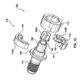
- FIG. 1C is an exploded view of the valve 100.
- the knockdown retainer 110 includes knockdown pieces 110A, 110B.
- the knockdown pieces (also called “the pieces of the retainer") 110A, 110B are held together by a non-positive attachment.
- the pieces of the retainer 110A, 110B are constrained to stay together when they are position within the barrel 104.
- the retainer pieces 110A, 110B are not fixedly attached to each other (such as with a bolt).
- the retainer 110 is easily separable into multiple pieces or multiple sections (that is, retainer pieces 110A, 110B).
- the knockdown joint 117 joins the retainer 110 with the stem 106 so that the retainer 110 is knocked down or off from the stem 106.
- the knockdown joint 117 also permits slidably fitting or mating of the retainer 110 with the stem 106, but in a non-positive manner (that is, by not using bolts, etc, to firmly and positively bolt or attach the retainer 110 with the stem 106).
- the knockdown joint 117 includes a slide-type joint, which includes: (i) a tongue 118, and (ii) a groove 120 that is slide matable (slip engagable) with the tongue 118.
- the tongue 118 extends from at least one retainer piece 110A, 110B.
- the stem 106 defines the groove 120 (preferably, the groove 120 is defined around an outer surface of the stem 106).
- the knockdown joint 117 assists in maintaining the retainer 110 in a substantially constant axial position relative to the stem 106.
- an outer diameter of the retainer 110 abuts (or is proximate to) an inner diameter of the barrel 104, and (ii) the retainer 110 maintains its relative (axial) position with the stem 106 while the valve 100 operates.
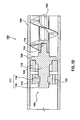
- FIG. 1D is a cross-sectional view of the valve 100 of FIG. 1A .
- the screw 102 is made to rotate and to force a molding material into the valve 100 and through the passage 122.
- the screw 102 stops rotating and the screw 102 is thrust forwardly to force the valve 100 to close (the ring 112 is made to abut the rearward retainer 108) and thus the molding material is pushed out from the accumulation zone, through a nozzle (not depicted) and into a mold cavity (not depicted).
- the ring 112 abuts the rearward retainer 108 to prevent backflow of molding material from the valve 100 towards the screw 102.
- the screw 102 is retracted so that: (i) the rearward retainer 108 slides away from the ring 112 and (ii) the ring 112 is made to abut the retainer 110, which then opens the valve 100 and allows molding material to pass through the valve 100 and into the accumulation zone 180.
- a tongue extends from a selected one piece of the retainer 110, through a bore in the stem 106 and engages a groove defined by another selected piece or section of the retainer 110.
- the barrel 104 is disconnected from the nozzle (not depicted).
- the screw 102 is moved forwardly such that the valve 100 exits the barrel 104.
- the retainer 110 is readily removable from the stem 106.
- a rubber mallet may be used to strike and thereby disengage the retainer 110 from the stem 106.
- the screw 102 is retracted into the barrel 104, the barrel 104 is closed and preparation for a subsequent cycle of the molding system 10 may begin.
- Certain molten metals and metallic alloys (such as magnesium) used in thixomolding and/or metal molding react with oxygen at a temperature above the solidius temperature.
- molten metals and metallic alloys such as magnesium
- a more involved process is required for replacement of valve components in a thixomolding system or a metal molding system since direct exposure of the metal alloy to air may cause the metal to bum.
- Replacement of valve components in a thixomolding or metal molding application is further discussed in the descriptions of FIGS. 5A to 5C .
- FIG. 2 is a longitudinal cross-sectional view of a valve 200 (hereinafter referred to as "the valve 200") according to the second embodiment.
- the elements of the second exemplary embodiment are identified by reference numerals that use a two-hundred designation rather than a one-hundred designation (as used in the first exemplary embodiment).
- the retainer 210 of the second exemplary embodiment is labeled 210 rather than being labeled 110.
- a slide-type joint 217 slidably mates the retainer 210 with a stem 206.
- the slide-type joint 217 includes a tongue 220 and groove218.
- the groove 218 is defined by the retainer 210.
- the tongue 220 extends from the stem 206, and the tongue 220 is matable with the groove 218 thereby assisting in maintaining the retainer 210 in a substantially constant axial position relative to the stem 206 (once the retainer 210 is inserted into the barrel 204 as the tongue 220 and the groove 218 maintain inter-engagement with each other).
- the outer diameter of the retainer 210 abuts the inner diameter of the barrel 204 to maintain the pieces or the sections of the retainer 210 in cooperation with each other.
- the outer diameter of the tongue 220 is less than the inner diameter of the ring 212. This arrangement improves ease of assembly of the valve 200.
- the knockdown joint 117, 217 includes multiple tongues and grooves so that: (i) some tongues extend from the retainer 110, 210 while other tongues extend from the stem 106, 206, and (ii) some grooves are defined by the retainer 110,210 while other grooves are defined by the stem 106, 206.
- FIG. 3 is a longitudinal cross-sectional view of a valve 300 (hereinafter referred to as "the valve 300") according to the third embodiment.
- the valve 300 a valve 300
- elements of the third exemplary embodiment that are similar to those of the first exemplary embodiment
- reference numerals that use a three-hundred designation rather than a one-hundred designation are identified by reference numerals that use a three-hundred designation rather than a one-hundred designation (as used in the first exemplary embodiment).
- the retainer 310 of the third exemplary embodiment is labeled 310 rather than being labeled 110.
- the slide-type joint 317 (optionally) includes a tongue 318 and groove 320.
- the groove 320 is defined around the outer surface of the stem 306.
- the width of the groove 320 is configured to accommodate the full width of the retainer 310.
- the tongue 318 extends from the retainer 310.
- a profile shape of the tongue 118, 218, 318 and of the groove 120, 220, 320 may be any one of a sharp-edged rectangular profile, a round-edged rectangular profile, a semi-circular profile, and a wedge-like profile.
- the knockdown joint 317 includes a dowel 350.
- the dowel 350 is used to engage (in a knockdown approach): (i) engage the retainer 310 to the stem 306, and/or (ii) engage the retainer 310 to the stem 306.
- the retainer 310 defines a retainer bore 352
- the stem 306 defines a stem bore 354, and a dowel 350 extends into the retainer bore 352 and into the stem bore 354
- the retainer 310 defines the retainer bore 352
- a stem dowel (not depicted) extends from the stem 306 into the retainer bore 352
- the stem 306 defines the stem bore 354
- a retainer dowel (not depicted, but it is a modified dowel 350) extends from the retainer 310 into the stem bore 354.
- the knockdown retainer 310 includes a unitary body that is joined to the stem 306 by a dowel 350.
- FIG. 4 depicts frontal views of variants of the valve 100 of FIG. 1 .
- the variant retainers 110C, 110D, 110E, 110F, 110G, 110H include (but other variants are not limited to) a 2-, 3- or 4-piece construction.
- the retainers 110C, 110D include retainer pieces (two and three respectively) that are substantially equal in size.
- the retainer 110E includes retainer pieces (four pieces) that are unequal in size.
- the variant retainers 110C, 110D, 110E depict the passageway 122, 222, 322 defined as being circular in shape.
- the variant retainers 110F, 110G depict the passageway 122 defined as being arcuate shaped.
- the variant retainer 110G depicts the passage 122 defined as being defined in part by the barrel 104.
- FIGS. 5A to 5C are longitudinal cross-sectional views of the valve 100 of FIG. 1 used in a barrel of a metal-molding system (preferable, a thixo-molding system 1201). As previously mentioned, FIGS. 5A to 5C depict a method of servicing (such as replacing valve components) of a valve 100 that is operatively connected to a molding system 10, particularly of a thixomolding system.
- FIG. 5A is a longitudinal cross-sectional view of a distal end of a barrel 1204 of the thixomolding system 1201.
- a heater 1214 is coupled to the barrel 1204.
- a barrel head 1228 is attached to the barrel 1204 by a set of bolts 1226A, 1226B.
- the barrel 1204 houses a screw 1202 for processing a molding material (such as a metallic molding material).
- the valve 100 is attached to the distal end of the screw 1202. Any one of the valves 100, 200 or 300 may be attached to the screw 1202.
- the temperature of a distal end of the barrel 1204 is lowered by reducing or turning off the output of the heater 1214.
- the remainder of the material within the barrel 1204 is kept (maintained) in non-solid state by maintaining other heaters (not depicted) operational.
- the solidifying molding material proximate to the valve 100 is permitted to weld the valve 100 to the barrel 1204, and in response a seal is created.
- the seal blocks oxygen from entering the barrel 1204 and reaching the molten molding material contained in the barrel 1204 once the barrel head 1228 is removed from the barrel 1204.
- the bolts 1226A, 1226B can be loosened and the barrel head 1228 may then be removed without incurring risk of exposing the molten molding material (melt located behind the seal and in the barrel) to air, whereupon it could ignite.
- FIG. 5B is a longitudinal cross-sectional view of the distal end of the barrel 1204 of a FIG. 5A following removal of the barrel head 1228.
- a valve-service cap 1220 (hereafter referred to as "the cap 1220") is installed to the barrel 1204.
- the cap 1220 is: (i) attached to the distal end of the barrel 1204 by a set of removal cap screws 1222A, 1222B, and/or (ii) is preferably made of a weld-proof material (that is, not reactive to the molding material) such as a highly thermally resistant plastic or rubber, etc.
- the cap 1220 defines a catch basin 1224, and the cap 1220 is used to receive the valve 100.
- the cap 1220 is filled with an inert gas, such as argon, prior to installation of the cap 1220 onto the barrel 1204.
- the inert gas does not react to molten metallic molding material (such as magnesium, etc).
- a port extends from the cap 1220 so that the inert gas may enter the cap 1220 after the cap 1220 has been installed to the barrel 1204.
- the heater 1214 is made to supply heat to the distal end of the barrel 1204, increasing the temperature and returning the solidified material located proximate to the valve 100 to a molten (non-solid) state.
- the inert gas does not react with the molten metallic alloy.
- the screw 1202 is translated forwardly, pushing the valve 100 into the catch basin.
- the heater 1214 is turned off so as to re-solidify the molten molding material located in the distal end of the screw 1202 and the barrel 1204.
- the solidified melt creates an airtight seal around the distal end of the screw 1202 and the barrel 1202 to thus prevent air from entering into the barrel 1204.
- the removal cap screws 1222A, 1222B are then loosened and the cap 1220 is detached or removed from the barrel 1204.
- the valve 100 protrudes out of the distal end of the barrel 1204 allowing service access to components of the valve 100, such as the ring 112, which can be inspected, removed, cleaned and/or replaced, etc.
- the retainer 110 Since the retainer 110 is non-positively engaged to the stem 106 (that is, it is knockably removable from the stem 106), the retainer 110 falls off of the stem 106. At times, the retainer 110 may not simply fall off the stem 106 since solidified molding material may still remain at the interfaces between the retainer 110 and the stem 106.
- the retainer 110 can be disengaged from the valve 100 once the valve has been made to protrude from the distal end of the barrel 1204 by striking the retainer 110 with a rubber mallet or similar device (once all the melt has solidified and the catch basin is removed).
- FIG. 5C is a longitudinal cross-sectional view of the distal end of the barrel 1204 of a FIG. 5A following replacement of the components of the valve 100.
- the ring 112 and the retainer 110 have been replaced by a new ring 1226 and a new retainer 1228 respectively.
- the new retainer 1228 is held in place, by a clamp or other retention means (not depicted), as the cap 1220 is slid over the valve 100.
- the clamp or other retention means can be removed and the cap 1220 can be made to abut the distal end of the barrel 1204 thereby encapsulating the valve 100.
- Installation cap screws 1232A and 1232B attach the cap 1220 to the barrel 1204.
- the cap 1220 Following attachment of the cap 1220, (i) the cap is pumped with inert gas and (ii) output of the heater 1214 is increased to melt the solidified melt located in the distal end of the barrel 1204.
- the screw 1202 is retracted when the solidified melt has sufficiently melted, pulling the valve 100 within the barrel 1204. Once the valve 100 is sufficiently within the barrel 1204, the output of the heater 1214 is once again reduced in the distal end of the barrel 1204 to create a seal of solidified melt.
- the cap 1220 is then removed and replaced by the barrel head 1228 of FIG. 5A . Once the barrel head 1228 is installed, the heater 1214 is used to melt the solidified melt within the barrel 1204, allowing normal operation of the thixomolding system to resume normal operation.
Landscapes
- Engineering & Computer Science (AREA)
- Mechanical Engineering (AREA)
- Manufacturing & Machinery (AREA)
- Injection Moulding Of Plastics Or The Like (AREA)
- Valve Housings (AREA)
- Closures For Containers (AREA)
- Fluid-Driven Valves (AREA)
- Continuous Casting (AREA)
- Moulds For Moulding Plastics Or The Like (AREA)
Claims (3)
- Verfahren zum Warten eines Formungssystemventils (100; 200; 300), bei welchem;eine Verfestigung eines geschmolzenen Formungsmaterials gestattet wird, um das Formungssystemventil (100; 200; 300) an eine Trommel (1204) zu schweißen, wobei das Formungssystemventil (100; 200; 300) an einer Schnecke (1202) eines Thixo-Formungssystems (1201) befestigt ist, und als Reaktion darauf eine Dichtung erzeugt wird, wobei die Trommel (1204) abgedichtet wird, so daß Sauerstoff daran gehindert wird, in die Trommel (1204) einzutreten und das in der Trommel (1204) enthaltene geschmolzene Formungsmaserial zu erreichen;ein Rest des geschmolzenen Formungsmaterials in der Trommel (1204) in einem nicht festen Zustand gehalten wird;ein Trommelkopf (1228) von der Trommel (1204) entfernt wird, sobald die Trommel (1204) luftdicht abgedichtet ist, so daß das geschmolzene Formungsmaterial hinter der Dichtung und in der Trommel (1204) der Luft nicht ausgesetzt wird;eine Kappe (1220) an der Trommel (1204) installiert wird;ein distales Ende der Trommel (1204) erhitzt wird, und als Reaktion das verfestigte Material, das in der Nähe des Formungssystemventils (100; 200; 300) vorhanden ist, in einen geschmolzenen Zustand zurückgeführt wird;die Schnecke (1202) in einer Translationsbewegung vorwärtsbewegt wird, so daß das Formungssystemventil (100; 200; 300) in die Kappe (1220) gedrückt wird;eine Verfestigung des geschmolzenen Formungsmaterials gestattet wird, um die Trommel (1204) abzudichten;das Formungssystemventil (100; 200; 300) gewartet wird;das distale Ende der Trommel (1204) erhitzt wird, und als Reaktion die verfestigte Schmelze, die in dem distalen Ende der Trommel (1204) vorhanden ist, wieder geschmolzen wird; unddie Schnecke (1202) zurückgezogen wird, und als Reaktion das Formungssystemventil in die Trommel (1204) eingezogen wird.
- Verfahren nach Anspruch 1, bei welchem:die Kappe (1220) mit einem inerten Gas gefüllt wird.
- Verfahren nach Anspruch 1, bei welchem:die Kappe (1220) entfernt wird, um das Formungssyst.emventil (100; 200; 300) zu exponieren.
Applications Claiming Priority (2)
| Application Number | Priority Date | Filing Date | Title |
|---|---|---|---|
| US11/435,589 US7353858B2 (en) | 2006-05-17 | 2006-05-17 | Cap for servicing molding-system valve |
| PCT/CA2007/000643 WO2007131320A1 (en) | 2006-05-17 | 2007-04-19 | Cap for servicing molding-system valve |
Publications (3)
| Publication Number | Publication Date |
|---|---|
| EP2019745A1 EP2019745A1 (de) | 2009-02-04 |
| EP2019745A4 EP2019745A4 (de) | 2009-06-24 |
| EP2019745B1 true EP2019745B1 (de) | 2010-03-31 |
Family
ID=38693476
Family Applications (1)
| Application Number | Title | Priority Date | Filing Date |
|---|---|---|---|
| EP07719570A Not-in-force EP2019745B1 (de) | 2006-05-17 | 2007-04-19 | Verfahren zur wartung eines ventils in einem giesssystem |
Country Status (8)
| Country | Link |
|---|---|
| US (1) | US7353858B2 (de) |
| EP (1) | EP2019745B1 (de) |
| CN (1) | CN101443178B (de) |
| AT (1) | ATE462550T1 (de) |
| CA (1) | CA2649860C (de) |
| DE (1) | DE602007005632D1 (de) |
| TW (1) | TWI312311B (de) |
| WO (1) | WO2007131320A1 (de) |
Families Citing this family (3)
| Publication number | Priority date | Publication date | Assignee | Title |
|---|---|---|---|---|
| US9057556B2 (en) | 2008-01-21 | 2015-06-16 | Whirlpool Corporation | Select fill sensor system for refrigerator dispensers |
| US8813816B2 (en) | 2012-09-27 | 2014-08-26 | Apple Inc. | Methods of melting and introducing amorphous alloy feedstock for casting or processing |
| WO2021154291A1 (en) * | 2020-01-31 | 2021-08-05 | Cunningham Charles Stephen | Modular injection molding barrel and screw assemblies |
Family Cites Families (15)
| Publication number | Priority date | Publication date | Assignee | Title |
|---|---|---|---|---|
| US903A (en) | 1838-08-30 | Machine for turning treenails | ||
| US1102A (en) | 1839-03-15 | Machine for cutting straw | ||
| US1941573A (en) * | 1932-09-20 | 1934-01-02 | Fuller Co | Conveying system |
| US4062479A (en) | 1976-10-14 | 1977-12-13 | Bruce Plastics, Inc. | Non-return valve assemblies in injection molding machines |
| US4377180A (en) * | 1980-11-10 | 1983-03-22 | Component Manufacturing & Design, Inc. | Non-return valve for plastic injection molding |
| DE3203724A1 (de) | 1982-02-04 | 1983-08-11 | Krauss-Maffei AG, 8000 München | Rueckstroemsperre |
| US5044926A (en) | 1990-06-25 | 1991-09-03 | Cincinnati Milacron Inc. | Anti-backflow valve for injection molding machines |
| US5258158A (en) | 1991-05-13 | 1993-11-02 | Dray Robert F | Positive-type non-return valve and method of using valve |
| US5630463A (en) * | 1994-12-08 | 1997-05-20 | Nelson Metal Products Corporation | Variable volume die casting shot sleeve |
| US5680894A (en) * | 1996-10-23 | 1997-10-28 | Lindberg Corporation | Apparatus for the injection molding of a metal alloy: sub-ring concept |
| US5983978A (en) * | 1997-09-30 | 1999-11-16 | Thixomat, Inc. | Thermal shock resistant apparatus for molding thixotropic materials |
| JP3357303B2 (ja) * | 1998-11-05 | 2002-12-16 | 株式会社日本製鋼所 | 金属射出成形機の逆流防止装置 |
| US6520762B2 (en) * | 2001-02-23 | 2003-02-18 | Husky Injection Molding Systems, Ltd | Injection unit |
| JP2004082178A (ja) | 2002-08-28 | 2004-03-18 | Japan Steel Works Ltd:The | 射出成形機および前記射出成形機の整備方法 |
| US7255151B2 (en) * | 2004-11-10 | 2007-08-14 | Husky Injection Molding Systems Ltd. | Near liquidus injection molding process |
-
2006
- 2006-05-17 US US11/435,589 patent/US7353858B2/en not_active Expired - Fee Related
-
2007
- 2007-04-19 AT AT07719570T patent/ATE462550T1/de not_active IP Right Cessation
- 2007-04-19 WO PCT/CA2007/000643 patent/WO2007131320A1/en not_active Ceased
- 2007-04-19 CN CN2007800177090A patent/CN101443178B/zh not_active Expired - Fee Related
- 2007-04-19 DE DE602007005632T patent/DE602007005632D1/de active Active
- 2007-04-19 EP EP07719570A patent/EP2019745B1/de not_active Not-in-force
- 2007-04-19 CA CA2649860A patent/CA2649860C/en not_active Expired - Fee Related
- 2007-05-07 TW TW096116129A patent/TWI312311B/zh not_active IP Right Cessation
Also Published As
| Publication number | Publication date |
|---|---|
| DE602007005632D1 (de) | 2010-05-12 |
| US20070267779A1 (en) | 2007-11-22 |
| CN101443178A (zh) | 2009-05-27 |
| TWI312311B (en) | 2009-07-21 |
| EP2019745A4 (de) | 2009-06-24 |
| CA2649860A1 (en) | 2007-11-22 |
| TW200804059A (en) | 2008-01-16 |
| WO2007131320A1 (en) | 2007-11-22 |
| CA2649860C (en) | 2011-06-21 |
| US7353858B2 (en) | 2008-04-08 |
| EP2019745A1 (de) | 2009-02-04 |
| CN101443178B (zh) | 2011-06-15 |
| ATE462550T1 (de) | 2010-04-15 |
Similar Documents
| Publication | Publication Date | Title |
|---|---|---|
| US5983978A (en) | Thermal shock resistant apparatus for molding thixotropic materials | |
| DE69017966T2 (de) | Verfahren und vorrichtung zum einspritzgiessformen von metallegierungen. | |
| CA2649868C (en) | Molding-system valve having knockdown retainer | |
| JP4119892B2 (ja) | 軽金属射出成形機の射出装置 | |
| EP2019745B1 (de) | Verfahren zur wartung eines ventils in einem giesssystem | |
| EP2782692A2 (de) | Druckgussdüse und verfahren zum betrieb einer druckgussdüse sowie heizelement und heizpatrone per se | |
| US20090107646A1 (en) | Metal-Molding Conduit Assembly of Metal-Molding System | |
| US20070065538A1 (en) | Molding system having valve including pump | |
| WO2005098290A1 (en) | Non-return valve for use in a molding system | |
| EP1507613B1 (de) | Spritzgiessverfahren und -vorrichtung mit basismontierter zuführvorrichtung | |
| JP4695624B2 (ja) | 成形システムの導管接続部 | |
| US20030094257A1 (en) | Shutterless injection molding method and apparatus | |
| US20090025901A1 (en) | Molding System with Barrel Assembly | |
| JPH11156519A (ja) | 金属材料の射出装置 | |
| JP2005161375A (ja) | 金属射出成形機の金属溶湯供給装置 | |
| US20080089969A1 (en) | Barrel head of extruder of molding system, barrel head having outer and inner portions, amongst other things | |
| KR20070032024A (ko) | 사출 성형기용 체크 밸브 립 밀봉부 |
Legal Events
| Date | Code | Title | Description |
|---|---|---|---|
| PUAI | Public reference made under article 153(3) epc to a published international application that has entered the european phase |
Free format text: ORIGINAL CODE: 0009012 |
|
| 17P | Request for examination filed |
Effective date: 20081121 |
|
| AK | Designated contracting states |
Kind code of ref document: A1 Designated state(s): AT BE BG CH CY CZ DE DK EE ES FI FR GB GR HU IE IS IT LI LT LU LV MC MT NL PL PT RO SE SI SK TR |
|
| AX | Request for extension of the european patent |
Extension state: AL BA HR MK RS |
|
| RAP1 | Party data changed (applicant data changed or rights of an application transferred) |
Owner name: HUSKY INJECTION MOLDING SYSTEMS S.A. |
|
| A4 | Supplementary search report drawn up and despatched |
Effective date: 20090527 |
|
| 17Q | First examination report despatched |
Effective date: 20090708 |
|
| GRAP | Despatch of communication of intention to grant a patent |
Free format text: ORIGINAL CODE: EPIDOSNIGR1 |
|
| RTI1 | Title (correction) |
Free format text: METHOD OF SERVICING MOLDING-SYSTEM VALVE |
|
| GRAS | Grant fee paid |
Free format text: ORIGINAL CODE: EPIDOSNIGR3 |
|
| GRAA | (expected) grant |
Free format text: ORIGINAL CODE: 0009210 |
|
| RAP1 | Party data changed (applicant data changed or rights of an application transferred) |
Owner name: HUSKY INJECTION MOLDING SYSTEMS LTD. |
|
| AK | Designated contracting states |
Kind code of ref document: B1 Designated state(s): AT BE BG CH CY CZ DE DK EE ES FI FR GB GR HU IE IS IT LI LT LU LV MC MT NL PL PT RO SE SI SK TR |
|
| REG | Reference to a national code |
Ref country code: GB Ref legal event code: FG4D Ref country code: CH Ref legal event code: EP |
|
| REG | Reference to a national code |
Ref country code: IE Ref legal event code: FG4D |
|
| REF | Corresponds to: |
Ref document number: 602007005632 Country of ref document: DE Date of ref document: 20100512 Kind code of ref document: P |
|
| REG | Reference to a national code |
Ref country code: NL Ref legal event code: VDEP Effective date: 20100331 |
|
| PG25 | Lapsed in a contracting state [announced via postgrant information from national office to epo] |
Ref country code: LT Free format text: LAPSE BECAUSE OF FAILURE TO SUBMIT A TRANSLATION OF THE DESCRIPTION OR TO PAY THE FEE WITHIN THE PRESCRIBED TIME-LIMIT Effective date: 20100331 |
|
| LTIE | Lt: invalidation of european patent or patent extension |
Effective date: 20100331 |
|
| PG25 | Lapsed in a contracting state [announced via postgrant information from national office to epo] |
Ref country code: FI Free format text: LAPSE BECAUSE OF FAILURE TO SUBMIT A TRANSLATION OF THE DESCRIPTION OR TO PAY THE FEE WITHIN THE PRESCRIBED TIME-LIMIT Effective date: 20100331 Ref country code: AT Free format text: LAPSE BECAUSE OF FAILURE TO SUBMIT A TRANSLATION OF THE DESCRIPTION OR TO PAY THE FEE WITHIN THE PRESCRIBED TIME-LIMIT Effective date: 20100331 Ref country code: LV Free format text: LAPSE BECAUSE OF FAILURE TO SUBMIT A TRANSLATION OF THE DESCRIPTION OR TO PAY THE FEE WITHIN THE PRESCRIBED TIME-LIMIT Effective date: 20100331 Ref country code: PL Free format text: LAPSE BECAUSE OF FAILURE TO SUBMIT A TRANSLATION OF THE DESCRIPTION OR TO PAY THE FEE WITHIN THE PRESCRIBED TIME-LIMIT Effective date: 20100331 Ref country code: SI Free format text: LAPSE BECAUSE OF FAILURE TO SUBMIT A TRANSLATION OF THE DESCRIPTION OR TO PAY THE FEE WITHIN THE PRESCRIBED TIME-LIMIT Effective date: 20100331 |
|
| PG25 | Lapsed in a contracting state [announced via postgrant information from national office to epo] |
Ref country code: SE Free format text: LAPSE BECAUSE OF FAILURE TO SUBMIT A TRANSLATION OF THE DESCRIPTION OR TO PAY THE FEE WITHIN THE PRESCRIBED TIME-LIMIT Effective date: 20100331 Ref country code: CY Free format text: LAPSE BECAUSE OF FAILURE TO SUBMIT A TRANSLATION OF THE DESCRIPTION OR TO PAY THE FEE WITHIN THE PRESCRIBED TIME-LIMIT Effective date: 20100331 Ref country code: EE Free format text: LAPSE BECAUSE OF FAILURE TO SUBMIT A TRANSLATION OF THE DESCRIPTION OR TO PAY THE FEE WITHIN THE PRESCRIBED TIME-LIMIT Effective date: 20100331 Ref country code: ES Free format text: LAPSE BECAUSE OF FAILURE TO SUBMIT A TRANSLATION OF THE DESCRIPTION OR TO PAY THE FEE WITHIN THE PRESCRIBED TIME-LIMIT Effective date: 20100712 Ref country code: NL Free format text: LAPSE BECAUSE OF FAILURE TO SUBMIT A TRANSLATION OF THE DESCRIPTION OR TO PAY THE FEE WITHIN THE PRESCRIBED TIME-LIMIT Effective date: 20100331 Ref country code: RO Free format text: LAPSE BECAUSE OF FAILURE TO SUBMIT A TRANSLATION OF THE DESCRIPTION OR TO PAY THE FEE WITHIN THE PRESCRIBED TIME-LIMIT Effective date: 20100331 Ref country code: BE Free format text: LAPSE BECAUSE OF FAILURE TO SUBMIT A TRANSLATION OF THE DESCRIPTION OR TO PAY THE FEE WITHIN THE PRESCRIBED TIME-LIMIT Effective date: 20100331 |
|
| PG25 | Lapsed in a contracting state [announced via postgrant information from national office to epo] |
Ref country code: SK Free format text: LAPSE BECAUSE OF FAILURE TO SUBMIT A TRANSLATION OF THE DESCRIPTION OR TO PAY THE FEE WITHIN THE PRESCRIBED TIME-LIMIT Effective date: 20100331 Ref country code: MC Free format text: LAPSE BECAUSE OF NON-PAYMENT OF DUE FEES Effective date: 20100430 Ref country code: IS Free format text: LAPSE BECAUSE OF FAILURE TO SUBMIT A TRANSLATION OF THE DESCRIPTION OR TO PAY THE FEE WITHIN THE PRESCRIBED TIME-LIMIT Effective date: 20100731 Ref country code: CZ Free format text: LAPSE BECAUSE OF FAILURE TO SUBMIT A TRANSLATION OF THE DESCRIPTION OR TO PAY THE FEE WITHIN THE PRESCRIBED TIME-LIMIT Effective date: 20100331 |
|
| PG25 | Lapsed in a contracting state [announced via postgrant information from national office to epo] |
Ref country code: DK Free format text: LAPSE BECAUSE OF FAILURE TO SUBMIT A TRANSLATION OF THE DESCRIPTION OR TO PAY THE FEE WITHIN THE PRESCRIBED TIME-LIMIT Effective date: 20100331 Ref country code: PT Free format text: LAPSE BECAUSE OF FAILURE TO SUBMIT A TRANSLATION OF THE DESCRIPTION OR TO PAY THE FEE WITHIN THE PRESCRIBED TIME-LIMIT Effective date: 20100802 Ref country code: IE Free format text: LAPSE BECAUSE OF NON-PAYMENT OF DUE FEES Effective date: 20100419 |
|
| PLBE | No opposition filed within time limit |
Free format text: ORIGINAL CODE: 0009261 |
|
| STAA | Information on the status of an ep patent application or granted ep patent |
Free format text: STATUS: NO OPPOSITION FILED WITHIN TIME LIMIT |
|
| 26N | No opposition filed |
Effective date: 20110104 |
|
| PG25 | Lapsed in a contracting state [announced via postgrant information from national office to epo] |
Ref country code: IT Free format text: LAPSE BECAUSE OF FAILURE TO SUBMIT A TRANSLATION OF THE DESCRIPTION OR TO PAY THE FEE WITHIN THE PRESCRIBED TIME-LIMIT Effective date: 20100331 |
|
| PG25 | Lapsed in a contracting state [announced via postgrant information from national office to epo] |
Ref country code: MT Free format text: LAPSE BECAUSE OF FAILURE TO SUBMIT A TRANSLATION OF THE DESCRIPTION OR TO PAY THE FEE WITHIN THE PRESCRIBED TIME-LIMIT Effective date: 20100331 |
|
| PG25 | Lapsed in a contracting state [announced via postgrant information from national office to epo] |
Ref country code: BG Free format text: LAPSE BECAUSE OF FAILURE TO SUBMIT A TRANSLATION OF THE DESCRIPTION OR TO PAY THE FEE WITHIN THE PRESCRIBED TIME-LIMIT Effective date: 20100331 Ref country code: HU Free format text: LAPSE BECAUSE OF FAILURE TO SUBMIT A TRANSLATION OF THE DESCRIPTION OR TO PAY THE FEE WITHIN THE PRESCRIBED TIME-LIMIT Effective date: 20101001 |
|
| PG25 | Lapsed in a contracting state [announced via postgrant information from national office to epo] |
Ref country code: TR Free format text: LAPSE BECAUSE OF FAILURE TO SUBMIT A TRANSLATION OF THE DESCRIPTION OR TO PAY THE FEE WITHIN THE PRESCRIBED TIME-LIMIT Effective date: 20100331 |
|
| PGFP | Annual fee paid to national office [announced via postgrant information from national office to epo] |
Ref country code: CH Payment date: 20130328 Year of fee payment: 7 |
|
| PGFP | Annual fee paid to national office [announced via postgrant information from national office to epo] |
Ref country code: LU Payment date: 20130405 Year of fee payment: 7 |
|
| PGFP | Annual fee paid to national office [announced via postgrant information from national office to epo] |
Ref country code: DE Payment date: 20130328 Year of fee payment: 7 Ref country code: GB Payment date: 20130402 Year of fee payment: 7 |
|
| PGFP | Annual fee paid to national office [announced via postgrant information from national office to epo] |
Ref country code: FR Payment date: 20130430 Year of fee payment: 7 |
|
| PG25 | Lapsed in a contracting state [announced via postgrant information from national office to epo] |
Ref country code: BG Free format text: LAPSE BECAUSE OF FAILURE TO SUBMIT A TRANSLATION OF THE DESCRIPTION OR TO PAY THE FEE WITHIN THE PRESCRIBED TIME-LIMIT Effective date: 20100630 |
|
| PG25 | Lapsed in a contracting state [announced via postgrant information from national office to epo] |
Ref country code: GR Free format text: LAPSE BECAUSE OF FAILURE TO SUBMIT A TRANSLATION OF THE DESCRIPTION OR TO PAY THE FEE WITHIN THE PRESCRIBED TIME-LIMIT Effective date: 20100331 |
|
| REG | Reference to a national code |
Ref country code: DE Ref legal event code: R119 Ref document number: 602007005632 Country of ref document: DE |
|
| PG25 | Lapsed in a contracting state [announced via postgrant information from national office to epo] |
Ref country code: LU Free format text: LAPSE BECAUSE OF NON-PAYMENT OF DUE FEES Effective date: 20140419 |
|
| REG | Reference to a national code |
Ref country code: CH Ref legal event code: PL |
|
| GBPC | Gb: european patent ceased through non-payment of renewal fee |
Effective date: 20140419 |
|
| REG | Reference to a national code |
Ref country code: FR Ref legal event code: ST Effective date: 20141231 |
|
| REG | Reference to a national code |
Ref country code: DE Ref legal event code: R119 Ref document number: 602007005632 Country of ref document: DE Effective date: 20141101 |
|
| PG25 | Lapsed in a contracting state [announced via postgrant information from national office to epo] |
Ref country code: CH Free format text: LAPSE BECAUSE OF NON-PAYMENT OF DUE FEES Effective date: 20140430 Ref country code: GB Free format text: LAPSE BECAUSE OF NON-PAYMENT OF DUE FEES Effective date: 20140419 Ref country code: DE Free format text: LAPSE BECAUSE OF NON-PAYMENT OF DUE FEES Effective date: 20141101 Ref country code: LI Free format text: LAPSE BECAUSE OF NON-PAYMENT OF DUE FEES Effective date: 20140430 |
|
| PG25 | Lapsed in a contracting state [announced via postgrant information from national office to epo] |
Ref country code: FR Free format text: LAPSE BECAUSE OF NON-PAYMENT OF DUE FEES Effective date: 20140430 |