EP2019807B1 - Procédé et système d'installation de rails guides d'ascenseurs - Google Patents
Procédé et système d'installation de rails guides d'ascenseurs Download PDFInfo
- Publication number
- EP2019807B1 EP2019807B1 EP07730610.8A EP07730610A EP2019807B1 EP 2019807 B1 EP2019807 B1 EP 2019807B1 EP 07730610 A EP07730610 A EP 07730610A EP 2019807 B1 EP2019807 B1 EP 2019807B1
- Authority
- EP
- European Patent Office
- Prior art keywords
- guide rail
- rail section
- alignment
- fixed
- proximity
- Prior art date
- Legal status (The legal status is an assumption and is not a legal conclusion. Google has not performed a legal analysis and makes no representation as to the accuracy of the status listed.)
- Not-in-force
Links
- 238000000034 method Methods 0.000 title claims description 34
- 238000010276 construction Methods 0.000 claims description 3
- 230000000750 progressive effect Effects 0.000 claims description 3
- 239000007787 solid Substances 0.000 claims description 2
- 238000009434 installation Methods 0.000 description 7
- 230000006978 adaptation Effects 0.000 description 1
- 238000012512 characterization method Methods 0.000 description 1
- 238000007796 conventional method Methods 0.000 description 1
- 239000000428 dust Substances 0.000 description 1
- 230000007613 environmental effect Effects 0.000 description 1
- 230000014509 gene expression Effects 0.000 description 1
- 230000003252 repetitive effect Effects 0.000 description 1
- 238000003466 welding Methods 0.000 description 1
Images

Classifications
-
- B—PERFORMING OPERATIONS; TRANSPORTING
- B66—HOISTING; LIFTING; HAULING
- B66B—ELEVATORS; ESCALATORS OR MOVING WALKWAYS
- B66B7/00—Other common features of elevators
- B66B7/02—Guideways; Guides
-
- B—PERFORMING OPERATIONS; TRANSPORTING
- B66—HOISTING; LIFTING; HAULING
- B66B—ELEVATORS; ESCALATORS OR MOVING WALKWAYS
- B66B19/00—Mining-hoist operation
- B66B19/002—Mining-hoist operation installing or exchanging guide rails
Definitions
- the present invention relates to a method as defined in the preamble of claim 1.
- the present invention relates to a system as defined in the preamble of claim 11.
- a prior art method for installing the guide rails, such as the car guide rails and/or counterweight guide rails, of an elevator in the elevator shaft or similar is made in the prior art method, to which reference is made in the description of the prior art in publication US 6422352 .
- the guide rails are installed by assembly in stages, starting from the bottom of the elevator shaft, by placing guide rail sections that are shorter than the whole length of the guide rail one consecutively after the other and by aligning the guide rail sections vertically by means of a perpendicular laser beam produced by a direction laser.
- plumb lines suspended from the machine room above the shaft, from floor levels or a from separate scaffold is Likewise a prior art system for assembling guide rails in the elevator shaft from consecutive guide rail sections, which system comprises a direction laser, which produces a perpendicular laser beam for aligning the guide rail sections.
- the purpose of the invention is to eliminate at least part of the aforementioned drawbacks.
- a purpose of the invention is to disclose a method that enables the use of inexpensive direction lasers in the installation of guide rails, such that environmental conditions do not affect the alignment accuracy of the guide rails.
- Another purpose of the invention is to disclose a system for implementing the method.
- the direction laser is moved upwards along with progressive assembly of the guide rail, and as assembly progresses the direction laser is supported on a fixed structure of the elevator shaft, such as on the wall of the elevator shaft or on a fixing element secured to the wall of the elevator shaft, in the proximity of the top end of each topmost perpendicularly aligned guide rail section for alignment of the next guide rail section to be installed in the vertical direction. These phases are repeated until the entire guide rail is assembled.
- the direction laser is supported on a fixed structure, such as on the wall of the elevator shaft or on a structure of it, which is essentially immovable with respect to the wall of the elevator shaft or similar, installation of the guide rails is possible with few vibration problems. What is essential is that the fixing point is secure in the way that the direction laser is essentially not subjected to e.g. vibrations caused in the guide rail installation work. If the direction laser were fixed to a guide rail subjected to vibration, it would cause problems of vibration of the direction laser. Vibration is caused by, among other things, impacts on the lower guide rails occurring in connection with installation of the upper guide rails.
- One advantage of the invention is that a lightweight and inexpensive laser can be used as a direction laser. As a result of the invention it is sufficient that the bunch of beams remains narrow and distinct and produces a round, point-form lighting pattern over a relatively short distance.
- a self-leveling construction measuring laser is used as a direction laser, which forms an automatically perpendicular laser beam.
- the alignment appliance is fixed to the guide rail section at a point that is in the proximity of the fixing element of the guide rail section to be fixed at that time.
- the direction laser in phase t) is moved upwards by a distance interval, which is preferably in the order of magnitude of 10 meters.
- the distance interval can in fact be greater or smaller than this.
- the guide rails are assembled from the bottom upwards as pairs of guide rail sections.
- the method is ensured, by means of an alignment plumb line extending between the alignment appliances connected to the first and second guide rail sections and of alignment marks on the alignment appliances, that the first and second guide rail section of the guide rail pairs, which comprise a first guide rail section and a second guide rail section diametrically opposite to each other, are in the pre-defined correct position both with respect to each other and to the vertical and horizontal planes when the alignment plumb line is at the point of the first and the second alignment mark. It is possible thus to ensure that the guide rail sections are not e.g. twisted around their vertical axes.
- the direction laser is supported on a fixed structure of the elevator shaft via a support device.
- the support device is preferably a rod-like fixing element, which is preferably formed to be adjustable, in which case the direction laser can be positioned in exactly the desired place and positioning is easy to perform. The direction laser can thus be kept separate from the guide rails and excessive vibration is avoided.
- the system according to the invention comprises an alignment appliance.
- the alignment appliance comprises a frame, which contains a detent, which can be supported against the guide rail section.
- a permanent magnet is fixed to the frame in the proximity of the detent for fixing the frame to the guide rail section.
- the alignment appliance contains an aligning element, at which the laser beam produced by the direction laser can be directed.
- the aligning element of the alignment appliance can with the arrangement be accurately positioned with respect to the detent.
- the system also comprises a support device for supporting the direction laser on a fixed structure, such as on the wall of the elevator shaft or on a fixing element securely fixed to the wall of the elevator shaft.
- the direction laser can thus be kept separate from the guide rails and excessive vibration is avoided.
- the support device is preferably formed to be adjustable, in which case the direction laser can be positioned very accurately.
- the magnet is on the side of the base of the slot incorporated in the alignment appliance and arranged to pull the guide rail towards the base of the slot or recess of the alignment appliance. In this way it is possible to ensure good repeatability of the positioning between the alignment appliance and the guide rail.
- the magnet can be installed to the side of the slot to pull the guide rail and the alignment appliance towards each other in the lateral direction.
- the alignment appliance comprises a magnet at the base of and on the side of the slot or recess of the alignment appliance so that the magnet attracts the guide rail in two directions.
- the system comprises an alignment plumb line, which is fixed at its first end to the first alignment appliance, which can be fixed to the first guide rail section.
- the alignment plumb line is fixed at its second end to a second alignment appliance, which can be fixed to the diametrically opposite second guide rail section.
- the second alignment appliance is in shape an identical mirror image of the first alignment appliance.
- the first alignment mark is on the first alignment appliance at a distance from the first end of the alignment plumb line.
- the second alignment mark is on the second alignment appliance at a distance from the second end of the plumb line.
- the first and the second guide rail section are in the pre-defined correct position both with respect to each other and to the vertical and horizontal planes when the alignment plumb line is at the point of the first alignment mark and the second alignment mark. It is possible thus to ensure that the guide rail sections are not twisted around their vertical axes.
- the system comprises one direction laser for each guide rail to be assembled.
- the fixed structure is the wall of the elevator shaft or similar structure of the elevator shaft or a beam securely fixed to the elevator shaft or a fixing element of the guide rail.
- a fixed structure can be e.g. a part of the framework of the elevator shaft or similar.
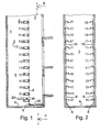
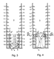
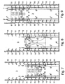
- Figs. 1-4 and 7-9 diagrammatically present the different phases of assembly of the guide rails in the elevator shaft with a manner according to one embodiment of the method according to the invention
- Fig. 1 shows a longitudinal cross-section of an elevator shaft and in the figure is a II-II section of Fig. 1.
- Figs. 1 and 2 illustrate the preliminary phase before the actual assembly of the guide rails, in which a plurality of fixing elements 11, to which the guide rails of the car and/or counterweight are intended to be fixed, are initially fixed to the vertical walls of the elevator shaft 3. It should be noted that in Figs. 1 - 4 and 7 - 9 the relative distance between the fixing elements 11 has been reduced in the vertical direction to be substantially smaller than the actual situation to facilitate illustration and drawing technique.
- the installation and alignment of the fixing elements 11 can be performed with any conventional method whatsoever, such as e.g. with plumb lines.
- the same direction lasers 8 that are used in the method according to the invention are utilized.
- a self-leveling construction measuring laser is used as the direction laser 8, which automatically forms a perpendicular laser beam 9.
- the direction lasers 8 are placed at the bottom 4 of the elevator shaft 3 by measuring with a measuring rod 24 their position from the front wall of the elevator shaft.
- Fixing holes are drilled on the same vertical line in the vertical wall 10 of the elevator shaft for the fixing elements 11 by means of the laser beam 9.
- the fixing bolts of the fixing elements 11 are installed in these holes and are positioned to be horizontal using a conventional spirit level 25 as an aid. In this way all the fixing elements 11 are installed for the whole length of the elevator shaft 3.
- the guide rails 1,2 are installed by assembly in phases, starting from the bottom 4 of the elevator shaft, by placing one on top of the other guide rail sections 5 1 , 5 2 ; 6 1 , 6 2 ; 7 1 , 7 2 that are shorter than the whole length of the guide rail. This is performed with pairs of guide rail sections.
- the guide rails 1, 2 are assembled in the guide rail section pairs 5 1 , 5 2 ; 6 1 , 6 2 ; 7 1 , 7 2 ... from the bottom upwards.
- the guide rail sections are aligned vertically by means of the perpendicular laser beams 9 produced by the direction lasers 8.
- the direction lasers 8 are moved upwards along with progressive assembly of the guide rails 1, 2.
- the direction laser is supported in the proximity of the top end of the topmost vertically aligned guide rail section at the time for aligning the next guide rail section to be installed in the vertical direction, and these phases are repeated until the entire guide rail 1, 2 is assembled.
- the direction laser 8 is supported on the fixing element 11. Supporting the direction laser 8 on the wall 10 of the elevator shaft can be implemented in a similar manner. Fixing the support device 23 of the direction laser on a fixed structure of the elevator shaft can be performed with some prior art method, such as with a screw fixing, with a magnet or by welding.
- an alignment appliance 12 which contains an aligning element 13, is fixed to the guide rail section 5 1 , 5 2 ; (and also 6 1 , 6 2 ; 7 1 , 7 2 etc) to be aligned at a distance from the direction laser 8.
- the guide rail section 5 1 , 5 2 to be aligned is moved in the lateral direction so that the aligning element 13 faces the laser beam 9, after which the guide rail section 5 1 , 5 2 to be aligned can be fixed to the fixing element 11.
- the alignment appliance 12 is always fixed to a point of the guide rail section 5 1 , 5 2 that is in the proximity of the fixing element 11 to be fixed at that time to the guide rail section.
- Fig. 3 presents the installation and alignment of the bottommost pair of guide rail sections 5 1 , 5 2 by means of the laser beams 9 of the direction lasers 8.
- the direction laser 8 is placed at the bottom 4 of the elevator shaft 3 beside the bottommost guide rail section.
- the alignment appliance 12 is fixed to the bottommost guide rail section 5 1 , 5 2 in the proximity of the bottommost fixing element 11, which is described in phase 1 (the figure 1 inside a circle) of Fig. 1 .
- the guide rail section 5 1 , 5 2 is moved in the lateral direction so that the aligning element 13 faces the laser beam 9, after which the guide rail section 5 1 , 5 2 can be fixed securely to the fixing element 11.
- the alignment appliance 12 is in the proximity of the next higher fixing element 11. The phases are repeated, as is illustrated with the circled numbers 2, 3 and 4, for each fixing element 11 until the entire bottommost guide rail section 5 1 , 5 2 is aligned and fixed to the fixing elements 11.
- the alignment appliance 12 is left in place in the proximity of the top end of the bottommost guide rail section 5 1 , 5 2 when the direction laser 8 is moved from the bottom 4 of the elevator shaft upwards and connected to a fixed structure in the proximity of the alignment appliance 12 that is disposed in the proximity of the top end of the bottommost guide rail section 5 1 , 5 2 , which phase 5 ( figure 5 inside a circle) presents in Fig. 4 .
- the direction laser 8 is moved upwards by the distance interval L, which is e.g. in the order of magnitude of approx. 10 meters.
- the direction laser 8 is aligned with the previous vertical line such that the direction laser 8 is adjusted in the lateral direction so that the laser beam 9 hits the aligning element 13 of the alignment appliance 12 left in the proximity of the top end of the bottommost guide rail section 5 1 , 5 2 , and the direction laser 8 is fixed in position with respect to the bottommost guide rail section.
- the alignment appliance 12 in Fig. 7 is removed from the lower guide rail section 5 1 , 5 2 and the alignment appliance 12 is moved upwards to the proximity of the bottommost fixing element 11 of the next guide rail section 6 1 , 6 2 to be aligned.
- the guide rail section 6 1 , 6 2 to be aligned is moved so that the aligning element 13 faces the laser beam 9.
- the guide rail section is fixed to the fixing element 11.
- the alignment appliance 12 is removed and fixed in the proximity of the next higher fixing element 11.
- the phases are repeated, as is illustrated with the circled numbers 6, 7, 8 and 9, for each fixing element 11 until the entire guide rail section 6 1 , 6 2 is aligned and fixed to the fixing elements 11.
- the alignment appliance 12 is left in place in the proximity of the top end of the bottommost guide rail section 6 1 , 6 2 when the direction laser 8 is moved by the amount of the distance interval L, which is preferably in the order of magnitude of approx. 10 meters, and connected to a fixed structure in the proximity of the alignment appliance 12 that is disposed in the proximity of the top end of the aligned guide rail section.
- the direction laser 8 in Fig. 8 is directed by means of the alignment appliance 12 left in the proximity of the top end of the guide rail section 6 1 , 6 2 so that the laser beam hits the aligning element 13 of the alignment appliance, and the direction laser 8 is fixed in place.
- Fig. 9 further illustrates, the corresponding phases are repeated until the entire guide rail 1, 2 is assembled to completion.
- the guide rail section pairs comprise a first guide rail section 5 1 (and further 6 1 , 7 1 ...) and a second guide rail section 5 2 (and further 6 2 , 7 2 ...) that are diametrically opposite to each other.
- the alignment plumb line 15 extending between the alignment appliances 12 connected to the first and to the second guide rail section and of the alignment marks 16, 17 on the alignment appliances, it is ensured that the guide rail sections in the guide rail section pair are on the same vertical plane e.g. after fixing one guide rail section and before fixing a second guide rail section.
- the alignment appliance 12 comprises a frame 18, which contains a detent 19, such as an edge, a recess or a U-shaped slot, as in the figures, which can be supported against the guide rail section 5 1 , 5 2 (and further 6 1 , 6 2 ; 7 1 , 7 2 ... ).
- the permanent magnet 20 is fixed to the frame 18 in the proximity of the detent 19 for fixing the frame 18 to the guide rail section 5 1 , 5 2 (and further 6 1 , 6 2 ; 7 1 , 7 2 ).
- On the frame is an aligning element 13, at which the laser beam 9 produced by the direction laser 8 can be directed.
- the aligning element 13 can be e.g. a window, in which is an alignment grid or similar, on which the laser beam 9 forms a lighting point.
- the alignment plumb line 15 is fixed at its first end 21 to the first alignment appliance 12 1 , which can be fixed to the first guide rail section 5 1 (and further 6 1 , 7 1 ), and which alignment plumb line is fixed at its second end 22 to the second alignment appliance 12 2 , which can be fixed to the diametrically opposite second guide rail section 5 2 (and further 6 2 , 7 2 ).
- the second alignment appliance 12 2 is in shape an identical mirror image of the first alignment appliance 12 1 .
- the first alignment mark 16 is on the first alignment appliance 12 1 at a distance from the first end 21 of the alignment plumb line 15.
- the second alignment mark 17 is on the second alignment appliance 12 2 at a distance from the second end 22 of the alignment plumb line 15.
- the first and second guide rail section are in the pre-defined correct position both with respect to each other and to the vertical and horizontal planes when the alignment plumb line is at the point of the first alignment mark 16 and the second alignment mark 17. It is possible thus to ensure that the diametrically opposite guide rail sections are not twisted around their vertical axes.
- Fig. 6 also shows an adjustable support device 23, with which the position of the direction laser 8 fixed to the support device can be adjusted and supported on a fixed structure (10, 11).
- the fixed structure can be the wall of the elevator shaft or similar structure of the elevator shaft or a beam securely fixed to the elevator shaft or a fixing element of the guide rail.
- the fixed structure can be e.g. a part of the framework of the elevator shaft or similar.
- An adjustable structure can be the structure presented in Fig. 6 , in which the support device extends from its fixing point to the proximity of the guide rail and comprises parts that are movable with respect to each other, which can be tightened into the desired position e.g. with a screw fixing.
Landscapes
- Lift-Guide Devices, And Elevator Ropes And Cables (AREA)
Claims (13)
- Procédé d'installation de rails de guidage (1, 2), tels que des rails de guidage de cabine ou de contrepoids, dans une cage d'ascenseur (3) ou similaire, dans lequel procédé les rails de guidage (1, 2) sont installés par l'assemblage par phases en commençant par le fond (4) de la cage d'ascenseur en plaçant les unes sur les autres des sections de rail de guidage (51, 52 ; 61, 62 ; 71, 72...) qui sont plus courtes que toute la longueur du rail de guidage et en alignant les sections de rails de guidage perpendiculairement au moyen du faisceau laser (9) produit par un laser directionnel (8), le laser directionnel (8) se déplaçant vers le haut avec la progression de l'assemblage du rail de guidage, caractérisé par le fait que, pendant que l'assemblage progresse, le laser directionnel (8) est supporté sur une structure fixe (10, 11) de la cage d'ascenseur, telle que sur la paroi (10) de la cage d'ascenseur ou sur un élément de fixation (11) solidement fixé à la paroi de la cage d'ascenseur, à proximité de l'extrémité supérieure de chaque section de rail de guidage alignée perpendiculairement la plus supérieure pour l'alignement de la section de rail de guidage suivante à installer dans la direction verticale, et ces phases sont répétées jusqu'à l'achèvement de la totalité du rail de guidage (1, 2).
- Procédé selon la revendication 1, caractérisé par le fait qu'un laser de mesure de construction auto-nivelant est utilisé comme laser directionnel (8), qui forme un faisceau laser automatiquement perpendiculaire (9).
- Procédé selon la revendication 1 ou 2, caractérisé par le fait quea) une pluralité d'éléments de fixation (11) pour fixer les rails de guidage (1, 2) sont fixés à la paroi verticale (10) de la cage d'ascenseur (3) ou à une structure solide similaire,b) un outil d'alignement (12), qui contient une élément d'alignement (13), est fixé à la section de rail de guidage (51, 52 ; 61, 62 ; 71, 72...) à aligner, à distance du laser directionnel (8),c) la section de rail de guidage (51, 52 ; 61, 62 ; 71, 72...) à aligner est déplacée dans la direction latérale de telle sorte que l'élément d'alignement (13) fait face au faisceau laser (9), etd) la section de rail de guidage (51, 52 ; 61, 62 ; 71, 72...) à aligner est fixée à l'élément de fixation (11).
- Procédé selon la revendication 3, caractérisé par le fait que l'élément d'alignement (12) est fixé à un point de la section de rail de guidage (51, 52 ; 61, 62 ; 71, 72...) qui est à proximité de l'élément de fixation (11) de la section de rail de guidage à fixer à ce moment.
- Procédé selon la revendication 3 ou 4, caractérisé par le fait quee) le laser directionnel (8) est placé au fond (4) de la cage d'ascenseur (3) pour aligner la section de rail de guidage la plus inférieure (51, 52),f) l'outil d'alignement (11) est fixé à la section de rail de guidage la plus inférieure (51, 52) à proximité de l'élément de fixation le plus inférieur (11),g) la section de rail de guidage (51, 52) est déplacée dans la direction latérale de telle sorte que l'élément d'alignement (13) fait face au faisceau laser (9),h) la section de rail de guidage (51, 52) est fixée à l'élément de fixation (11).i) l'outil d'alignement (12) est retiré et l'outil d'alignement est fixé à proximité de l'élément de fixation immédiatement supérieur (11),j) les phases g) à i) sont répétées jusqu'à ce que la totalité du rail de guidage le plus inférieur (51, 52) soit alignée et fixée aux éléments de fixation (11),k) l'outil d'alignement (12) est laissé en place à proximité de l'extrémité supérieure de la section de rail de guidage la plus inférieure (51, 52),l) le laser directionnel (8) est déplacé depuis le fond (4) de la cage d'ascenseur vers le haut et raccordé à une structure fixe à proximité de l'outil d'alignement (12) qui est disposé à proximité de l'extrémité supérieure de la section de rail de guidage la plus inférieure (51, 52), etm) le laser directionnel (8) est déplacé dans la direction latérale de telle sorte que le faisceau laser (9) atteint l'élément d'alignement (13) de l'outil d'alignement (12) laissé à proximité de l'extrémité supérieure de la section de rail de guidage la plus inférieure (51, 52), et le laser directionnel (8) est fixé en position par rapport à la section de rail de guidage la plus inférieure.
- Procédé selon la revendication 5, caractérisé par le fait quen) l'outil d'alignement (12) est retiré de la section de rail de guidage qui est plus basse à ce moment et l'outil d'alignement est déplacé vers le haut à proximité de l'élément de fixation le plus inférieur (11) de la section de rail de guidage suivante à aligner,o) la section de rail de guidage à aligner est déplacée de telle sorte que l'élément d'alignement (13) fait face au faisceau laser (9),p) la section de rail de guidage est fixée à l'élément de fixation (11),q) l'outil d'alignement (12) est retiré et l'outil d'alignement est fixé à proximité de l'élément de fixation immédiatement supérieur (11),r) les phases o) à q) sont répétées jusqu'à ce que la totalité du rail de guidage soit alignée et fixée aux éléments de fixation (11),s) l'outil d'alignement (12) est laissé en place à proximité de l'extrémité supérieure de la section de rail de guidage,t) le laser directionnel (8) est déplacé vers le haut et raccordé à une structure fixe à proximité de l'outil d'alignement (12) qui est disposé à proximité de l'extrémité supérieure de la section de rail de guidage alignée, etu) le laser directionnel (8) est dirigé au moyen de l'outil d'alignement (12) laissé à proximité de l'extrémité supérieure de la section de rail de guidage de telle sorte que le faisceau laser atteint l'élément d'alignement (13) de l'outil d'alignement, et le laser directionnel (8) est fixé en place,v) les phases n) à u) sont répétées jusqu'à l'achèvement du rail de guidage.
- Procédé selon la revendication 6, caractérisé par le fait que, à la phase t), le laser directionnel (8) est déplacé vers le haut par l'intervalle de distance (L), qui est de l'ordre de grandeur d'approximativement 10 mètres.
- Procédé selon l'une quelconque des revendications 1 à 7, caractérisé par le fait que les rails de guidage (1 , 2) sont assemblés en paires de section de rail de guidage (51, 52 ; 61, 62 ; 71, 72...) du bas vers le haut.
- Procédé selon l'une quelconque des revendications 1 à 8, caractérisé par le fait qu'il est assuré, au moyen d'un fil à plomb d'alignement (15) s'étendant entre les outils d'alignement (12) raccordé aux première et seconde sections de rail de guidage des paires de rail de guidage et de repères d'alignement (16, 17) des outils d'alignement, que les paires de section de rail de guidage, qui comprennent une première section de rail de guidage (51, 61, 71) et une seconde section de rail de guidage (52, 62, 72) diamétralement opposées l'une par rapport à l'autre, sont dans la position prédéfinie correcte l'une par rapport à l'autre après la fixation de la première section de rail de guidage et avant la fixation de la seconde section de rail de guidage.
- Procédé selon l'une quelconque des revendications 1 à 9, caractérisé par le fait que la structure fixe (10, 11) est la paroi (10) de la cage d'ascenseur ou une structure similaire de la cage d'ascenseur ou un faisceau solidement fixé à la cage d'ascenseur ou à un élément de fixation (11) du rail de guidage.
- Système d'installation de rails de guidage (1, 2), tels que des rails de guidage de cabine et/ou des rails de guidage de contrepoids, dans une cage d'ascenseur (3) à partir de sections de rail de guidage consécutives (51, 52 ; 61, 62 ; 71, 72...), lequel système d'ascenseur comprend au moins un laser directionnel (8), qui produit un faisceau laser perpendiculaire (9) pour aligner les sections de rail de guidage, caractérisé par le fait que le système comprend un dispositif de support (23) pour supporter le laser directionnel (8) sur une structure fixe (10, 11), telle que sur la paroi (10) de la cage d'ascenseur ou sur un élément de fixation (11) solidement fixé à la paroi de la cage d'ascenseur, et un outil d'alignement (12), qui comprend :- un châssis (18), qui contient un cran (19), qui peut être supporté contre la section de rail de guidage (51, 52 ; 61, 62 ; 71, 72...),- un aimant permanent (20), qui est fixé au châssis (18) à proximité du cran (19) pour fixer le châssis (18) à la section de rail de guidage (51, 52 ; 61, 62 ; 71, 72...), et- un élément d'alignement (13), au niveau duquel un faisceau laser (9) produit par un laser directionnel (8) peut être dirigé.
- Système selon la revendication 11, caractérisé par le fait que le système comporte un fil à plomb d'alignement (15), qui est fixé au niveau de sa première extrémité (21) au premier outil d'alignement (121), qui peut être fixé à la première section de rail de guidage (51, 61, 71), et lequel fil à plomb d'alignement est fixé au niveau de sa seconde extrémité (22) au second outil d'alignement (122), qui peut être fixé à la seconde section de rail de guidage diamétralement opposée (52, 62, 72), et lequel second outil d'alignement a une forme symétrique identique au premier outil d'alignement,- un premier repère d'alignement (16), qui est sur le premier outil d'alignement (121) à distance de la première extrémité (21) du fil à plomb d'alignement (15), et- un second repère d'alignement (17) sur le second outil d'alignement (122) à distance de la seconde extrémité (22) du fil à plomb d'alignement (15), dans lequel cas la première et la seconde section de rail de guidage sont dans la position correcte prédéfinie autant l'une par rapport à l'autre que par rapport au plan vertical et au plan horizontal lorsque le fil à plomb d'alignement est au niveau du premier repère d'alignement et du second repère d'alignement.
- Système selon la revendication 11 ou 12, caractérisé par le fait que le dispositif de support (23) est réglable pour positionner le laser directionnel (8).
Applications Claiming Priority (2)
| Application Number | Priority Date | Filing Date | Title |
|---|---|---|---|
| FI20060511A FI119983B (fi) | 2006-05-24 | 2006-05-24 | Menetelmä ja järjestelmä hissin johteiden asentamiseksi |
| PCT/FI2007/000141 WO2007135228A1 (fr) | 2006-05-24 | 2007-05-24 | Procédé et système d'installation de rails guides d'ascenseurs |
Publications (3)
| Publication Number | Publication Date |
|---|---|
| EP2019807A1 EP2019807A1 (fr) | 2009-02-04 |
| EP2019807A4 EP2019807A4 (fr) | 2013-10-23 |
| EP2019807B1 true EP2019807B1 (fr) | 2014-09-10 |
Family
ID=36539958
Family Applications (1)
| Application Number | Title | Priority Date | Filing Date |
|---|---|---|---|
| EP07730610.8A Not-in-force EP2019807B1 (fr) | 2006-05-24 | 2007-05-24 | Procédé et système d'installation de rails guides d'ascenseurs |
Country Status (5)
| Country | Link |
|---|---|
| US (1) | US8397437B2 (fr) |
| EP (1) | EP2019807B1 (fr) |
| CN (1) | CN101495396B (fr) |
| FI (1) | FI119983B (fr) |
| WO (1) | WO2007135228A1 (fr) |
Families Citing this family (33)
| Publication number | Priority date | Publication date | Assignee | Title |
|---|---|---|---|---|
| WO2006054982A2 (fr) * | 2004-11-16 | 2006-05-26 | Otis Elevator Company | Installation de rails de guidage dans un systeme d'ascenseurs |
| FI119321B (fi) * | 2006-11-02 | 2008-10-15 | Kone Corp | Menetelmä ja järjestelmä hissin johteiden asentamiseksi sekä järjestelmän käyttö hissin johteiden asentamisessa |
| FI120089B (fi) * | 2008-01-23 | 2009-06-30 | Kone Corp | Menetelmä hissin asentamiseksi |
| ES2572938T3 (es) * | 2010-04-30 | 2016-06-03 | Inventio Ag | Procedimiento y dispositivo para la instalación de un ascensor en una caja de ascensor |
| JP2012218833A (ja) * | 2011-04-05 | 2012-11-12 | Toshiba Elevator Co Ltd | エレベータ |
| US8302319B1 (en) | 2011-06-13 | 2012-11-06 | International Business Machines Corporation | Method and apparatus for aligning and leveling a server rack rail |
| DE102012104993A1 (de) * | 2012-06-11 | 2013-12-12 | Thyssenkrupp Elevator Ag | Verfahren und Montagesystem zur Montage von Aufzugskomponenten |
| EP2733105B1 (fr) * | 2012-11-20 | 2020-07-15 | Kone Corporation | Outil d'alignement d'ascenseur |
| CN102944186A (zh) * | 2012-12-06 | 2013-02-27 | 日立电梯(中国)有限公司 | 导轨的安装校正工具 |
| EP2821358B1 (fr) * | 2013-07-03 | 2016-11-30 | Kone Corporation | Système d'alignement de rail de guidage pour des ascenseurs |
| EP2873640B1 (fr) * | 2013-11-14 | 2016-06-01 | KONE Corporation | Appareil et procédé pour l'alignement d'un rail de guidage d'ascenseur |
| EP2955145B1 (fr) * | 2014-06-13 | 2016-12-21 | KONE Corporation | Appareil et procédé d'alignement de rails de guidage d'ascenseur |
| US10486943B2 (en) | 2014-10-30 | 2019-11-26 | Inventio Ag | Method for installing guide rails |
| JP2016155658A (ja) * | 2015-02-25 | 2016-09-01 | 三菱電機株式会社 | ガイドレール計測装置とガイドレール計測方法 |
| EP3085658B8 (fr) | 2015-04-23 | 2017-09-20 | KONE Corporation | Procédé et dispositif pour l'installation automatique d'un ascenseur |
| EP3085659B1 (fr) | 2015-04-23 | 2017-12-06 | KONE Corporation | Dispositif et procédé pour mesurer la position d'une plate-forme d'installation dans une cage d'ascenseur |
| EP3085657B1 (fr) | 2015-04-23 | 2017-08-23 | KONE Corporation | Appareil et procédé permettant l'alignement de rails de guidage dans une cage d'ascenseur |
| EP3118151B1 (fr) * | 2015-07-17 | 2019-06-12 | KONE Corporation | Support de rail de guidage d'ascenseur et procédé de fixation d'un rail de guidage |
| CN108367897B (zh) * | 2015-12-14 | 2020-04-14 | 因温特奥股份公司 | 用于建造电梯设备的方法和能够与增加的建筑物高度相匹配的电梯设备 |
| MX2019006015A (es) * | 2016-11-24 | 2019-08-01 | Inventio Ag | Metodo para montaje y dispositivo de alineacion para alineacion de riel guia de sistema de elevador. |
| CN108614239A (zh) * | 2016-12-12 | 2018-10-02 | 北京行易道科技有限公司 | 对准系统 |
| CN106494966B (zh) * | 2016-12-26 | 2018-09-25 | 汤井山 | 一种电梯导轨自动校准装置及校准方法 |
| CN111148711B (zh) * | 2017-09-27 | 2022-02-18 | 因温特奥股份公司 | 排齐装置和用于在电梯设备的电梯竖井中装配导轨的方法 |
| EP3466859B1 (fr) * | 2017-10-09 | 2023-11-29 | KONE Corporation | Procédé et agencement d'alignement de rail de guidage |
| JP2021095257A (ja) * | 2019-12-18 | 2021-06-24 | 株式会社日立ビルシステム | エレベータのレール据付装置 |
| ES2986975T3 (es) * | 2020-03-27 | 2024-11-13 | Inventio Ag | Consola universal y módulo de foso para un sistema de rieles de un sistema de ascensor, sistema de rieles y procedimiento para alinear el sistema de rieles |
| WO2021220344A1 (fr) * | 2020-04-27 | 2021-11-04 | 三菱電機株式会社 | Dispositif d'acquisition de données tridimensionnelles, système d'acquisition de données tridimensionnelles et procédé d'acquisition de données tridimensionnelles pour ascenseur |
| JP7027507B1 (ja) * | 2020-11-10 | 2022-03-01 | 東芝エレベータ株式会社 | レール設置支援装置、レール設置支援方法、レール設置支援システムおよびレール設置支援プログラム |
| WO2022242824A1 (fr) * | 2021-05-17 | 2022-11-24 | Kone Corporation | Procédé et agencement pour aligner des rails de guidage d'ascenseur |
| CN114608447B (zh) * | 2022-05-16 | 2022-07-12 | 深圳桥通物联科技有限公司 | 一种高效型电梯导轨安装精度校准设备 |
| JP2024000125A (ja) * | 2022-06-20 | 2024-01-05 | 株式会社日立ビルシステム | 細線位置検出器及びレール芯出し装置 |
| US12612741B2 (en) | 2023-02-23 | 2026-04-28 | Tee-Am, L.L.C. | Alignment apparatus |
| DE102024135425A1 (de) | 2024-11-29 | 2025-01-16 | Tk Elevator Innovation And Operations Gmbh | Positionierlehre und Positionierverfahren für Führungsschienenkonsolen einer Aufzugsanlage |
Family Cites Families (11)
| Publication number | Priority date | Publication date | Assignee | Title |
|---|---|---|---|---|
| US2402888A (en) * | 1944-08-02 | 1946-06-25 | Otis Elevator Co | Positioning apparatus for elevator guide rails |
| FR2269220B1 (fr) * | 1974-04-24 | 1979-09-28 | Essilor Int | |
| US4106207A (en) * | 1976-08-09 | 1978-08-15 | Vernon Hugo Boyett | Point to point self-leveling plumbing device |
| WO1985000222A1 (fr) * | 1983-06-21 | 1985-01-17 | Lasercheck Ltd. | Mesure de position a l'aide d'un rayon laser |
| US4593794A (en) * | 1984-04-23 | 1986-06-10 | Schindler Haughton Elevator Corporation | Apparatus and method for installing elevator rails |
| JPH06115851A (ja) * | 1992-10-05 | 1994-04-26 | Hitachi Building Syst Eng & Service Co Ltd | エレベーターの芯出し装置 |
| JP3173912B2 (ja) * | 1993-04-07 | 2001-06-04 | 株式会社日立ビルシステム | ガイドレールの芯出し方法 |
| FI109291B (fi) * | 1997-03-07 | 2002-06-28 | Kone Corp | Menetelmä ja laitteisto hissin asentamiseksi |
| US5931264A (en) * | 1997-09-25 | 1999-08-03 | Otis Elevator Company | Rail survey unit |
| FI116461B (fi) * | 2004-03-18 | 2005-11-30 | Kone Corp | Menetelmä hissin asentamiseksi ja hissin toimituskokonaisuus |
| US7654006B1 (en) * | 2007-09-07 | 2010-02-02 | Bret Mooney | Method and device for elevator rail alignment |
-
2006
- 2006-05-24 FI FI20060511A patent/FI119983B/fi not_active IP Right Cessation
-
2007
- 2007-05-24 WO PCT/FI2007/000141 patent/WO2007135228A1/fr not_active Ceased
- 2007-05-24 CN CN200780028294.7A patent/CN101495396B/zh not_active Expired - Fee Related
- 2007-05-24 EP EP07730610.8A patent/EP2019807B1/fr not_active Not-in-force
-
2008
- 2008-11-21 US US12/276,252 patent/US8397437B2/en not_active Expired - Fee Related
Also Published As
| Publication number | Publication date |
|---|---|
| US20090120734A1 (en) | 2009-05-14 |
| EP2019807A1 (fr) | 2009-02-04 |
| WO2007135228A1 (fr) | 2007-11-29 |
| FI20060511L (fi) | 2007-11-25 |
| EP2019807A4 (fr) | 2013-10-23 |
| US8397437B2 (en) | 2013-03-19 |
| CN101495396B (zh) | 2014-04-23 |
| CN101495396A (zh) | 2009-07-29 |
| FI20060511A0 (fi) | 2006-05-24 |
| FI119983B (fi) | 2009-05-29 |
Similar Documents
| Publication | Publication Date | Title |
|---|---|---|
| US8397437B2 (en) | Method for installing the guide rails of an elevator and system for installing the guide rails of an elevator | |
| CN103717521B (zh) | 用于对齐电梯的竖井门的方法和装置 | |
| US20090266651A1 (en) | Method and system for installing the guide rails of an elevator and use of the system in installing the guide rails of an elevator | |
| CN114455429B (zh) | 一种电梯导轨直线度测量及自动校准的装置及其应用 | |
| CN1219156A (zh) | 电梯的安装方法和装置 | |
| EP2955145B1 (fr) | Appareil et procédé d'alignement de rails de guidage d'ascenseur | |
| EP1812328B1 (fr) | Installation de rails de guidage dans un systeme d'ascenseurs | |
| JP6579591B1 (ja) | エレベータの乗場装置、エレベータの乗場装置の据え付け方法 | |
| WO2000047510A1 (fr) | Dispositif et procede pour le montage de rails-guides | |
| HK1133242B (en) | Method for installing the guide rails of an elevator and system for installing the guide rails of an elevator | |
| HK1133242A (en) | Method for installing the guide rails of an elevator and system for installing the guide rails of an elevator | |
| JP2010070268A (ja) | エレベータの据付方法および装置 | |
| JPH10218530A (ja) | エレベータガイドレールの芯出し装置 | |
| CN110926411B (zh) | 一种顶棚设计沉降量测量系统及方法 | |
| JP2008024387A (ja) | エレベータの据付治具 | |
| KR102189363B1 (ko) | 엘리베이터 설치용 형판 지그 장치 | |
| CN210944398U (zh) | 一种定位准确的复式楼电梯导向系统 | |
| CN114104926A (zh) | 层站组件定位工装及电梯层门组件安装方法 | |
| JPS5915178A (ja) | エレベ−タハンガケ−スの据付工法 | |
| HK1131600B (en) | Method and system for installing the guide rails of an elevator and use of the system in installing the guide rails of an elevator | |
| KR20070057947A (ko) | 승강기 시스템의 가이드 레일 설치 | |
| HK1195896B (en) | Method and device for aligning shaft doors of an elevator | |
| JP2008019047A (ja) | エレベータ用落下防止幕の取付装置及び取付方法 | |
| HK1117806A (en) | Installing guide rails in an elevator system |
Legal Events
| Date | Code | Title | Description |
|---|---|---|---|
| PUAI | Public reference made under article 153(3) epc to a published international application that has entered the european phase |
Free format text: ORIGINAL CODE: 0009012 |
|
| 17P | Request for examination filed |
Effective date: 20081124 |
|
| AK | Designated contracting states |
Kind code of ref document: A1 Designated state(s): AT BE BG CH CY CZ DE DK EE ES FI FR GB GR HU IE IS IT LI LT LU LV MC MT NL PL PT RO SE SI SK TR |
|
| AX | Request for extension of the european patent |
Extension state: AL BA HR MK RS |
|
| DAX | Request for extension of the european patent (deleted) | ||
| A4 | Supplementary search report drawn up and despatched |
Effective date: 20130920 |
|
| RIC1 | Information provided on ipc code assigned before grant |
Ipc: B66B 7/02 20060101AFI20130916BHEP Ipc: B66B 19/00 20060101ALI20130916BHEP |
|
| GRAP | Despatch of communication of intention to grant a patent |
Free format text: ORIGINAL CODE: EPIDOSNIGR1 |
|
| RIC1 | Information provided on ipc code assigned before grant |
Ipc: B66B 7/02 20060101AFI20140331BHEP Ipc: B66B 19/00 20060101ALI20140331BHEP |
|
| INTG | Intention to grant announced |
Effective date: 20140424 |
|
| GRAS | Grant fee paid |
Free format text: ORIGINAL CODE: EPIDOSNIGR3 |
|
| GRAA | (expected) grant |
Free format text: ORIGINAL CODE: 0009210 |
|
| AK | Designated contracting states |
Kind code of ref document: B1 Designated state(s): AT BE BG CH CY CZ DE DK EE ES FI FR GB GR HU IE IS IT LI LT LU LV MC MT NL PL PT RO SE SI SK TR |
|
| REG | Reference to a national code |
Ref country code: GB Ref legal event code: FG4D |
|
| REG | Reference to a national code |
Ref country code: CH Ref legal event code: EP |
|
| REG | Reference to a national code |
Ref country code: IE Ref legal event code: FG4D |
|
| REG | Reference to a national code |
Ref country code: AT Ref legal event code: REF Ref document number: 686573 Country of ref document: AT Kind code of ref document: T Effective date: 20141015 |
|
| REG | Reference to a national code |
Ref country code: DE Ref legal event code: R096 Ref document number: 602007038486 Country of ref document: DE Effective date: 20141016 |
|
| PG25 | Lapsed in a contracting state [announced via postgrant information from national office to epo] |
Ref country code: ES Free format text: LAPSE BECAUSE OF FAILURE TO SUBMIT A TRANSLATION OF THE DESCRIPTION OR TO PAY THE FEE WITHIN THE PRESCRIBED TIME-LIMIT Effective date: 20140910 Ref country code: GR Free format text: LAPSE BECAUSE OF FAILURE TO SUBMIT A TRANSLATION OF THE DESCRIPTION OR TO PAY THE FEE WITHIN THE PRESCRIBED TIME-LIMIT Effective date: 20141211 Ref country code: FI Free format text: LAPSE BECAUSE OF FAILURE TO SUBMIT A TRANSLATION OF THE DESCRIPTION OR TO PAY THE FEE WITHIN THE PRESCRIBED TIME-LIMIT Effective date: 20140910 Ref country code: SE Free format text: LAPSE BECAUSE OF FAILURE TO SUBMIT A TRANSLATION OF THE DESCRIPTION OR TO PAY THE FEE WITHIN THE PRESCRIBED TIME-LIMIT Effective date: 20140910 Ref country code: LT Free format text: LAPSE BECAUSE OF FAILURE TO SUBMIT A TRANSLATION OF THE DESCRIPTION OR TO PAY THE FEE WITHIN THE PRESCRIBED TIME-LIMIT Effective date: 20140910 |
|
| REG | Reference to a national code |
Ref country code: NL Ref legal event code: VDEP Effective date: 20140910 |
|
| REG | Reference to a national code |
Ref country code: LT Ref legal event code: MG4D |
|
| PG25 | Lapsed in a contracting state [announced via postgrant information from national office to epo] |
Ref country code: LV Free format text: LAPSE BECAUSE OF FAILURE TO SUBMIT A TRANSLATION OF THE DESCRIPTION OR TO PAY THE FEE WITHIN THE PRESCRIBED TIME-LIMIT Effective date: 20140910 Ref country code: CY Free format text: LAPSE BECAUSE OF FAILURE TO SUBMIT A TRANSLATION OF THE DESCRIPTION OR TO PAY THE FEE WITHIN THE PRESCRIBED TIME-LIMIT Effective date: 20140910 |
|
| REG | Reference to a national code |
Ref country code: AT Ref legal event code: MK05 Ref document number: 686573 Country of ref document: AT Kind code of ref document: T Effective date: 20140910 |
|
| PG25 | Lapsed in a contracting state [announced via postgrant information from national office to epo] |
Ref country code: NL Free format text: LAPSE BECAUSE OF FAILURE TO SUBMIT A TRANSLATION OF THE DESCRIPTION OR TO PAY THE FEE WITHIN THE PRESCRIBED TIME-LIMIT Effective date: 20140910 |
|
| PG25 | Lapsed in a contracting state [announced via postgrant information from national office to epo] |
Ref country code: CZ Free format text: LAPSE BECAUSE OF FAILURE TO SUBMIT A TRANSLATION OF THE DESCRIPTION OR TO PAY THE FEE WITHIN THE PRESCRIBED TIME-LIMIT Effective date: 20140910 Ref country code: SK Free format text: LAPSE BECAUSE OF FAILURE TO SUBMIT A TRANSLATION OF THE DESCRIPTION OR TO PAY THE FEE WITHIN THE PRESCRIBED TIME-LIMIT Effective date: 20140910 Ref country code: RO Free format text: LAPSE BECAUSE OF FAILURE TO SUBMIT A TRANSLATION OF THE DESCRIPTION OR TO PAY THE FEE WITHIN THE PRESCRIBED TIME-LIMIT Effective date: 20140910 Ref country code: IS Free format text: LAPSE BECAUSE OF FAILURE TO SUBMIT A TRANSLATION OF THE DESCRIPTION OR TO PAY THE FEE WITHIN THE PRESCRIBED TIME-LIMIT Effective date: 20150110 Ref country code: EE Free format text: LAPSE BECAUSE OF FAILURE TO SUBMIT A TRANSLATION OF THE DESCRIPTION OR TO PAY THE FEE WITHIN THE PRESCRIBED TIME-LIMIT Effective date: 20140910 Ref country code: PT Free format text: LAPSE BECAUSE OF FAILURE TO SUBMIT A TRANSLATION OF THE DESCRIPTION OR TO PAY THE FEE WITHIN THE PRESCRIBED TIME-LIMIT Effective date: 20150112 |
|
| PG25 | Lapsed in a contracting state [announced via postgrant information from national office to epo] |
Ref country code: AT Free format text: LAPSE BECAUSE OF FAILURE TO SUBMIT A TRANSLATION OF THE DESCRIPTION OR TO PAY THE FEE WITHIN THE PRESCRIBED TIME-LIMIT Effective date: 20140910 Ref country code: PL Free format text: LAPSE BECAUSE OF FAILURE TO SUBMIT A TRANSLATION OF THE DESCRIPTION OR TO PAY THE FEE WITHIN THE PRESCRIBED TIME-LIMIT Effective date: 20140910 |
|
| REG | Reference to a national code |
Ref country code: DE Ref legal event code: R097 Ref document number: 602007038486 Country of ref document: DE |
|
| PLBE | No opposition filed within time limit |
Free format text: ORIGINAL CODE: 0009261 |
|
| STAA | Information on the status of an ep patent application or granted ep patent |
Free format text: STATUS: NO OPPOSITION FILED WITHIN TIME LIMIT |
|
| PG25 | Lapsed in a contracting state [announced via postgrant information from national office to epo] |
Ref country code: DK Free format text: LAPSE BECAUSE OF FAILURE TO SUBMIT A TRANSLATION OF THE DESCRIPTION OR TO PAY THE FEE WITHIN THE PRESCRIBED TIME-LIMIT Effective date: 20140910 |
|
| 26N | No opposition filed |
Effective date: 20150611 |
|
| PG25 | Lapsed in a contracting state [announced via postgrant information from national office to epo] |
Ref country code: IT Free format text: LAPSE BECAUSE OF FAILURE TO SUBMIT A TRANSLATION OF THE DESCRIPTION OR TO PAY THE FEE WITHIN THE PRESCRIBED TIME-LIMIT Effective date: 20140910 |
|
| PG25 | Lapsed in a contracting state [announced via postgrant information from national office to epo] |
Ref country code: SI Free format text: LAPSE BECAUSE OF FAILURE TO SUBMIT A TRANSLATION OF THE DESCRIPTION OR TO PAY THE FEE WITHIN THE PRESCRIBED TIME-LIMIT Effective date: 20140910 |
|
| REG | Reference to a national code |
Ref country code: CH Ref legal event code: PL |
|
| PG25 | Lapsed in a contracting state [announced via postgrant information from national office to epo] |
Ref country code: CH Free format text: LAPSE BECAUSE OF NON-PAYMENT OF DUE FEES Effective date: 20150531 Ref country code: LU Free format text: LAPSE BECAUSE OF FAILURE TO SUBMIT A TRANSLATION OF THE DESCRIPTION OR TO PAY THE FEE WITHIN THE PRESCRIBED TIME-LIMIT Effective date: 20150524 Ref country code: LI Free format text: LAPSE BECAUSE OF NON-PAYMENT OF DUE FEES Effective date: 20150531 Ref country code: MC Free format text: LAPSE BECAUSE OF FAILURE TO SUBMIT A TRANSLATION OF THE DESCRIPTION OR TO PAY THE FEE WITHIN THE PRESCRIBED TIME-LIMIT Effective date: 20140910 |
|
| REG | Reference to a national code |
Ref country code: IE Ref legal event code: MM4A |
|
| PG25 | Lapsed in a contracting state [announced via postgrant information from national office to epo] |
Ref country code: IE Free format text: LAPSE BECAUSE OF NON-PAYMENT OF DUE FEES Effective date: 20150524 |
|
| REG | Reference to a national code |
Ref country code: FR Ref legal event code: PLFP Year of fee payment: 10 |
|
| PG25 | Lapsed in a contracting state [announced via postgrant information from national office to epo] |
Ref country code: BE Free format text: LAPSE BECAUSE OF FAILURE TO SUBMIT A TRANSLATION OF THE DESCRIPTION OR TO PAY THE FEE WITHIN THE PRESCRIBED TIME-LIMIT Effective date: 20140910 |
|
| PG25 | Lapsed in a contracting state [announced via postgrant information from national office to epo] |
Ref country code: MT Free format text: LAPSE BECAUSE OF FAILURE TO SUBMIT A TRANSLATION OF THE DESCRIPTION OR TO PAY THE FEE WITHIN THE PRESCRIBED TIME-LIMIT Effective date: 20140910 |
|
| REG | Reference to a national code |
Ref country code: FR Ref legal event code: PLFP Year of fee payment: 11 |
|
| PG25 | Lapsed in a contracting state [announced via postgrant information from national office to epo] |
Ref country code: HU Free format text: LAPSE BECAUSE OF FAILURE TO SUBMIT A TRANSLATION OF THE DESCRIPTION OR TO PAY THE FEE WITHIN THE PRESCRIBED TIME-LIMIT; INVALID AB INITIO Effective date: 20070524 Ref country code: BG Free format text: LAPSE BECAUSE OF FAILURE TO SUBMIT A TRANSLATION OF THE DESCRIPTION OR TO PAY THE FEE WITHIN THE PRESCRIBED TIME-LIMIT Effective date: 20140910 |
|
| PG25 | Lapsed in a contracting state [announced via postgrant information from national office to epo] |
Ref country code: TR Free format text: LAPSE BECAUSE OF FAILURE TO SUBMIT A TRANSLATION OF THE DESCRIPTION OR TO PAY THE FEE WITHIN THE PRESCRIBED TIME-LIMIT Effective date: 20140910 |
|
| REG | Reference to a national code |
Ref country code: FR Ref legal event code: PLFP Year of fee payment: 12 |
|
| PGFP | Annual fee paid to national office [announced via postgrant information from national office to epo] |
Ref country code: DE Payment date: 20190521 Year of fee payment: 13 |
|
| PGFP | Annual fee paid to national office [announced via postgrant information from national office to epo] |
Ref country code: FR Payment date: 20190523 Year of fee payment: 13 |
|
| PGFP | Annual fee paid to national office [announced via postgrant information from national office to epo] |
Ref country code: GB Payment date: 20190521 Year of fee payment: 13 |
|
| REG | Reference to a national code |
Ref country code: DE Ref legal event code: R119 Ref document number: 602007038486 Country of ref document: DE |
|
| GBPC | Gb: european patent ceased through non-payment of renewal fee |
Effective date: 20200524 |
|
| PG25 | Lapsed in a contracting state [announced via postgrant information from national office to epo] |
Ref country code: GB Free format text: LAPSE BECAUSE OF NON-PAYMENT OF DUE FEES Effective date: 20200524 Ref country code: FR Free format text: LAPSE BECAUSE OF NON-PAYMENT OF DUE FEES Effective date: 20200531 |
|
| PG25 | Lapsed in a contracting state [announced via postgrant information from national office to epo] |
Ref country code: DE Free format text: LAPSE BECAUSE OF NON-PAYMENT OF DUE FEES Effective date: 20201201 |