EP2019937B1 - Reduktionsgetriebevorrichtung mit verschachteltem planetengetriebe - Google Patents
Reduktionsgetriebevorrichtung mit verschachteltem planetengetriebe Download PDFInfo
- Publication number
- EP2019937B1 EP2019937B1 EP07766085A EP07766085A EP2019937B1 EP 2019937 B1 EP2019937 B1 EP 2019937B1 EP 07766085 A EP07766085 A EP 07766085A EP 07766085 A EP07766085 A EP 07766085A EP 2019937 B1 EP2019937 B1 EP 2019937B1
- Authority
- EP
- European Patent Office
- Prior art keywords
- toothing
- reduction device
- pinion
- contact
- intake
- Prior art date
- Legal status (The legal status is an assumption and is not a legal conclusion. Google has not performed a legal analysis and makes no representation as to the accuracy of the status listed.)
- Not-in-force
Links
- 230000004323 axial length Effects 0.000 claims description 8
- 238000005096 rolling process Methods 0.000 claims description 2
- 230000014759 maintenance of location Effects 0.000 claims 1
- 235000021183 entrée Nutrition 0.000 description 17
- 238000012550 audit Methods 0.000 description 5
- 230000007547 defect Effects 0.000 description 2
- 230000008030 elimination Effects 0.000 description 2
- 238000003379 elimination reaction Methods 0.000 description 2
- 238000012423 maintenance Methods 0.000 description 2
- 238000004519 manufacturing process Methods 0.000 description 2
- 230000004048 modification Effects 0.000 description 2
- 238000012986 modification Methods 0.000 description 2
- 238000007747 plating Methods 0.000 description 2
- 240000008042 Zea mays Species 0.000 description 1
- 239000000470 constituent Substances 0.000 description 1
- 238000009826 distribution Methods 0.000 description 1
- 238000005461 lubrication Methods 0.000 description 1
- 239000003607 modifier Substances 0.000 description 1
- 238000000465 moulding Methods 0.000 description 1
- 238000000926 separation method Methods 0.000 description 1
- 239000007787 solid Substances 0.000 description 1
Images


Classifications
-
- F—MECHANICAL ENGINEERING; LIGHTING; HEATING; WEAPONS; BLASTING
- F16—ENGINEERING ELEMENTS AND UNITS; GENERAL MEASURES FOR PRODUCING AND MAINTAINING EFFECTIVE FUNCTIONING OF MACHINES OR INSTALLATIONS; THERMAL INSULATION IN GENERAL
- F16H—GEARING
- F16H1/00—Toothed gearings for conveying rotary motion
- F16H1/28—Toothed gearings for conveying rotary motion with gears having orbital motion
- F16H1/46—Systems consisting of a plurality of gear trains each with orbital gears, i.e. systems having three or more central gears
Definitions
- the invention relates to a reduction device of the type with nested epicyclic gear trains, or "Fernandez" type planetary gear trains, as described in the reference work. Gears, by G. Henriot, DUNOD edition, page 534 , ⁇ 13.2.1.
- the reduction device also comprises a satellite carrier 30, coaxial with the input gear 12, on which are mounted the journals 32 around which the stepped gears 24 are rotated.
- the document JP 2003130145 discloses a reduction device of this type in which the satellite carrier is made in two parts and wherein the journals, around which the stepped gears are rotated, are mounted in "U" notches made on the satellite carrier, thus allowing a mounting from the side.
- the document EP-A - 319393 describes a device according to the preamble of claim 1.
- An object of the invention is to improve the known nested epicyclic gear type reduction devices and, in particular, to improve the maintenance of the stepped gears in their relative positions.
- the reduction device further comprises means interposed between said stepped gears which are adapted to maintain the relative positions of said stepped gears with respect to each other, said stepped gears rolling on said interposed means.
- the transverse plane located halfway axially from the zone of cooperation of said second tooth portion of said stepped gears with said output ring, is located at an axial distance from said first tooth portion of said stepped gears substantially equal to 80% of the axial length of said second tooth portion of said stepped gears.
- the means interposed, in simultaneous contact with the stepped gears allow to compensate for tangential tooth forces and radial and orthoradial tilting torques. This significantly improves the performance of the reduction device whether its performance, its life or comfort (sound) of use.
- the invention also relates to an outstanding clutch actuator and gearbox actuator in that they comprise a reduction device as described above.
- the first tooth portion 26a, 26b, 26c is in simultaneous contact with the input pinion 12 and the toothing 16 of the fixed ring 14, while the second tooth portion 28a, 28b, 28c is in contact with the toothing 20 of the output ring 18.
- the stepped gears 24a, 24b, 24c roll on a rotational element, in this case an idler gear 36, arranged substantially coaxially with the input gear 12.
- idler gear 36 is in contact only with second gear portion 28a, 28b, 28c stepped gears 24a, 24b, 24c.
- This idler gear 36 maintains the spacing between the stepped gears 24a, 24b, 24c and the parallelism between the axes of these gears.
- the operating pressure angle between the second tooth portion 28a, 28b, 28c and the idler gear 36 is small, ideally substantially equal to 20 °, so as to withstand the tilting torque which tends to move the stepped gears 24a, 24b, 24c of the idler gear 36.
- the operating pressure angle between the second toothing portion 28a, 28b, 28c and the toothing 20 of the output ring 18 is high, preferably substantially equal to 28 °.
- the transverse plane P located halfway axially from the zone of cooperation of the second toothing portion 28a, 28b, 28c with the output ring 18, is situated at an axial distance L1 with respect to the first tooth portion 26a. , 26b, 26c substantially equal to 80% of the axial length L2 of the second toothing portion 28a, 28b, 28c.
- a flexible retaining ring 38 is mounted without clearance with respect to the stepped gears 24a, 24b, 24c which it encircles, ideally only at the level of their second gear portion 28a, 28b, 28c. This flexible ring 38 further facilitates the mounting of the reduction device 34 by maintaining the nested elements.
- the axial length of the first toothing portion 26a, 26b, 26c of the stepped gears 24a, 24b, 24c is reduced to limit the tilting torque around an orthoradial axis.
- the flexible crown 38 mounted without play "initiates" the plating of the stepped gears 24a, 24b, 24c on the idler gear 36 when the reduction device does not transmit torque.
- This flexible ring 38 also makes it possible to fight against centrifugal forces during operation, in particular when empty.
- the reduction device according to the first embodiment of the invention has, in addition, the advantage of having fewer parts and fewer different parts.
- the reduction device of the state of the art comprises three stepped gears, a satellite carrier (possibly in two parts), three support pins of the stepped gears, and an input ring, a gear pinion. entrance and an output ring, or possibly, three or six bearings to be mounted between the trunnions and the satellite door.
- This device therefore comprises between ten and seventeen pieces which correspond to between six and eight references of different pieces.
- the reduction device according to the first embodiment of the invention for its part simply comprises between seven and eight pieces which correspond to between five and six different part numbers.
- the device therefore has a smaller number of parts, which leads to a reduction in manufacturing cost.
- its nomenclature has fewer references, which again allows a reduction in the cost of the reduction device compared to the known device.
- the device according to the invention also has, compared to the known device, the advantage of being easily mounted, to eliminate the problem of axial stop of the support pins of the stepped gears and the lubrication problems of the support bearings.
- the stepped gears can be made solid by molding, which allows a realization of reduced sized stepped gears, with less accurate dimensions and therefore less expensive manufacturing, or hollow so as to reduce the inertia of these gears spaced.
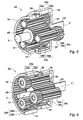
- This reduction device 40 differs from the reduction device 34 of the figures 2 and 3 in that it comprises stepped gears 24 made such that the first tooth portions 26 and second tooth portions 28 are spaced apart and connected by a smooth portion 42 without toothing.
- the stepped gears 24 roll on a smooth roller 44 mounted idle in rotation, and not on an idle gear, the stepped gears 24 bearing on the smooth roller 44 at their smooth portion 42 without toothing.
- This smooth roller 44 is disposed between the stepped gears 24 so as to take up the gear separation forces, this smooth roller 44 being in contact only with the smooth portion 42 of the stepped gears 24.
- the stepped gears 24 can, as shown in FIG. figure 4 , be mounted in rotation in a manner known per se by means of journals 32 rotatably mounted on a satellite carrier 30 which may optionally be made in two half-gate satellites in a manner known per se.
- the pins can be mounted either in "U" notches so as to allow mounting from the side, or in holes drilled in the satellite holder.
- idler gears 24 are here conceivable. It is thus conceivable to produce a plurality of smooth portions each cooperating with one or more smooth rollers, a preferred embodiment corresponding to the case where two smooth rollers are used. Moreover, the position of these smooth parts can also be modified. It is thus conceivable that these smooth parts are made on either side of the first or the second portion of teeth. It is also conceivable to make a smooth portion dividing the second portion of teeth in two.
- This reduction device 46 differs from the reduction device 34 according to the first preferred embodiment of the invention in that the input pinion 12 not only drives the stepped gears. 24a, 24b, 24c but also the maintenance of these stepped gears 24a, 24b, 24c, in their relative positions.
- the pinion 12 maintains the spacing between the stepped gears 24a, 24b, 24c and the parallelism between the axes of these gears.
- the pinion 12 used in this reduction device comprises a smooth portion 48 and a toothing portion 50 of length substantially equal to the length of the first tooth portion 26a, 26b, 26c stepped gears 24a, 24b , 24c, this first tooth portion being longer than the second tooth portion 28a, 28b, 28c.
- this first toothing portion 26a, 26b, 26c is such that the transverse plane located halfway axially from the cooperation zone of the first tooth portion 26a, 26b, 26c with the fixed entry ring 14, is located at an axial distance from the second tooth portion 28a, 28b, 28c substantially equal to 80% of the axial length of the first tooth portion 26a, 26b, 26c.
- the second preferred embodiment of the invention 52 shown in FIG. figure 6 differs from the device of the figure 5 that the tooth portion 50 of the input pinion 12 is in contact with the second tooth portion 28a, 28b, 28c of the stepped gears 24a, 24b, 24c.
- the tooth portion 50 of the input pinion 12 is of length substantially equal to the length of the second tooth portion 28a, 28b, 28c of the stepped gears 24a, 24b, 24c, this second tooth portion 28a, 28b, 28c being longer than the first tooth portion 26a, 26b, 26c.
- this second portion of toothing 28a, 28b, 28c is such that the transverse plane situated halfway axially from the zone of cooperation of the second toothing portion 28a, 28b, 28c with the output ring 18, is located at an axial distance from the first tooth portion 26a, 26b, 26c substantially equal to 80% of the axial length of the second toothing portion 28a, 28b, 28c.
- the second embodiment of the reduction device according to the invention has the particular advantage of further reducing the number of constituent parts of the reduction device and therefore its cost.
- the reduction devices according to the invention represented on the figures 2 , 3 and 6
- they can be implemented in a clutch actuator device or in a gearbox actuator device because of their wide range of reduction ratios, their small size and their very good efficiency.
- the flexible ring 38 can be made in the form of a smooth or toothed belt, a smooth ring or even a torus. This flexible ring 38 can be held in place axially by means of a groove formed in the first or second toothed portion of the stepped gears, respectively.
Landscapes
- Engineering & Computer Science (AREA)
- General Engineering & Computer Science (AREA)
- Mechanical Engineering (AREA)
- Retarders (AREA)
- Lubricants (AREA)
- General Details Of Gearings (AREA)
Claims (15)
- Untersetzungsvorrichtung von der Art mit ineinander greifenden Planetentrieben (34; 40; 46; 52) mit- einem Antriebszahnrad (12), das geeignet ist, um seine Achse drehangetrieben zu werden,- einem zu dem Antriebszahnrad (12) koaxialen festen Hohlrad (14), das auf seiner radial internen Seite eine Verzahnung (16) aufweist,- einem zu dem Antriebszahnrad (12) koaxialen Abtriebshohlrad (18), das auf seiner radial internen Seite eine Verzahnung (20) aufweist und koaxial und in der zu dem Antriebszahnrad (12) entgegengesetzten Richtung durch eine Abtriebswelle (22) fortgesetzt wird,- Stufenzahnrädern (24a, 24b, 24c), die umlaufend gleichmäßig verteilt sind und einen ersten und einen zweiten Verzahnungsbereich (26a, 26b, 26c, 28a, 28b, 28c) mit unterschiedlichem Durchmesser aufweisen, wobei der erste Verzahnungsbereich (26a, 26b, 26c) in Kontakt mit der Verzahnung (16) des festen Hohlrads (14) steht, wobei der zweite Verzahnungsbereich (28a, 28b, 28c) in Kontakt mit der Verzahnung (20) des Abtriebshohlrads (18) steht, wobei das Antriebszahnrad (12) in Kontakt mit dem ersten Verzahnungsbereich (26a, 26b, 26c) oder mit dem zweiten Verzahnungsbereich (28a, 28b, 28c) steht,- Mitteln, die zwischen den Stufenzahnrädern (24a, 24b, 24c) angeordnet sind und geeignet sind, um die relativen Positionen der Stufenzahnräder (24a, 24b, 24c) zueinander aufrechtzuerhalten, wobei die Stufenzahnräder (24a, 24b, 24c) auf den genannten zwischenangeordneten Mitteln rollen,dadurch gekennzeichnet, dass die Querebene (P), die sich axial in der Mitte des Bereichs befindet, in dem der zweite Verzahnungsbereich (28a, 28b, 28c) der Stufenzahnräder (24a, 24b, 24c) und das Abtriebshohlrad (18) zusammenarbeiten, von dem ersten Verzahnungsbereich (26a, 26b, 26c) der Stufenzahnräder (24a, 24b, 24c) um einen axialen Abstand (L1) beabstandet ist, der im Wesentlichen 80 % der axialen Länge (L2) des zweiten Verzahnungsbereichs (28a, 28b, 28c) der Stufenzahnräder (24a, 24b, 24c) entspricht.
- Untersetzungsvorrichtung nach Anspruch 1, dadurch gekennzeichnet, dass der Betriebsdruckwinkel zwischen dem zweiten Verzahnungsbereich (28a, 28b, 28c) und dem Abtriebshohlrad (18) in etwa 28° beträgt.
- Untersetzungsvorrichtung nach einem der vorhergehenden Ansprüche, dadurch gekennzeichnet, dass ein flexibles Haltehohlrad (38) die Stufenzahnräder (24a, 24b, 24c) vorzugsweise nur an deren zweitem Verzahnungsbereich (28a, 28b, 28c) umschließt.
- Untersetzungsvorrichtung nach einem der vorhergehenden Ansprüche, dadurch gekennzeichnet, dass die axiale Länge des ersten Verzahnungsbereichs (26a, 26b, 26c) der Stufenzahnräder (24a, 24b, 24c) kleiner ist als diejenige des zweiten Verzahnungsbereichs (28a, 28b, 28c).
- Untersetzungsvorrichtung nach einem der vorhergehenden Ansprüche, dadurch gekennzeichnet, dass die Vorrichtung ein zu dem Antriebszahnrad (12) koaxiales und in Kontakt mit den zweiten Verzahnungsbereichen stehendes Freilaufzahnrad (36) umfasst und dass der Betriebsdruckwinkel zwischen dem zweiten Verzahnungsbereich (28a, 28b, 28c) und dem Freilaufzahnrad (36) in etwa 20° beträgt.
- Untersetzungsvorrichtung nach einem der vorhergehenden Ansprüche, dadurch gekennzeichnet, dass die Stufenzahnräder (24a, 24b, 24c) frei drehend auf Zapfen (32) gelagert sind, welche auf einem Planetenträger (30) montiert sind.
- Untersetzungsvorrichtung nach einem der Ansprüche 1 bis 5, dadurch gekennzeichnet, dass sie keine Zapfen zur Lagerung der Stufenzahnräder und keinen Planetenträger aufweist.
- Untersetzungsvorrichtung nach einem der vorhergehenden Ansprüche, dadurch gekennzeichnet, dass die zwischenangeordneten Mittel nur mit dem ersten Verzahnungsbereich (26a, 26b, 26c) der Stufenzahnräder (24a, 24b, 24c) in Kontakt stehen.
- Untersetzungsvorrichtung nach einem der Ansprüche 1 bis 7, dadurch gekennzeichnet, dass die zwischenangeordneten Mittel nur mit dem zweiten Verzahnungsbereich (28a, 28b, 28c) der Stufenzahnräder (24a, 24b, 24c) in Kontakt stehen.
- Untersetzungsvorrichtung nach einem der vorhergehenden Ansprüche, dadurch gekennzeichnet, dass die zwischenangeordneten Mittel mindestens ein frei drehbares Element (36; 44) umfassen, das in etwa koaxial zu dem Antriebszahnrad (12) angeordnet ist.
- Vorrichtung nach dem vorhergehenden Anspruch, dadurch gekennzeichnet, dass das frei drehbare Element ein Freilaufzahnrad (36) umfasst, das in etwa koaxial zu dem Antriebszahnrad (12) angeordnet ist.
- Untersetzungsvorrichtung nach Anspruch 10, dadurch gekennzeichnet, dass die Stufenzahnräder (24a, 24b, 24c) zwischen den ersten und zweiten Verzahnungsbereichen (26a, 26b, 26c, 28a, 28b, 28c) einen Bereich ohne Verzahnung (42) aufweisen, wobei das frei drehbare Element mindestens eine Rolle (44) umfasst, die nur mit dem verzahnungslosen Bereich (42) in Kontakt steht.
- Untersetzungsvorrichtung nach einem der Ansprüche 1 bis 9, dadurch gekennzeichnet, dass die zwischenangeordneten Mittel durch das Antriebszahnrad (12) gebildet sind.
- Kupplungsaktuator, dadurch gekennzeichnet, dass er eine Untersetzungsvorrichtung nach einem der vorhergehenden Ansprüche umfasst.
- Getriebeaktuator, dadurch gekennzeichnet, dass er eine Untersetzungsvorrichtung nach einem der Ansprüche 1 bis 13 umfasst.
Applications Claiming Priority (2)
| Application Number | Priority Date | Filing Date | Title |
|---|---|---|---|
| FR0651897A FR2901591B1 (fr) | 2006-05-24 | 2006-05-24 | Dispositif de reduction du type a trains epicycloidaux imbriques |
| PCT/FR2007/051312 WO2007135338A1 (fr) | 2006-05-24 | 2007-05-22 | Dispositif de reduction du type a trains epicycloïdaux imbriques |
Publications (2)
| Publication Number | Publication Date |
|---|---|
| EP2019937A1 EP2019937A1 (de) | 2009-02-04 |
| EP2019937B1 true EP2019937B1 (de) | 2010-12-29 |
Family
ID=37763881
Family Applications (1)
| Application Number | Title | Priority Date | Filing Date |
|---|---|---|---|
| EP07766085A Not-in-force EP2019937B1 (de) | 2006-05-24 | 2007-05-22 | Reduktionsgetriebevorrichtung mit verschachteltem planetengetriebe |
Country Status (5)
| Country | Link |
|---|---|
| EP (1) | EP2019937B1 (de) |
| AT (1) | ATE493600T1 (de) |
| DE (1) | DE602007011597D1 (de) |
| FR (1) | FR2901591B1 (de) |
| WO (1) | WO2007135338A1 (de) |
Cited By (1)
| Publication number | Priority date | Publication date | Assignee | Title |
|---|---|---|---|---|
| DE102024118038A1 (de) * | 2024-06-26 | 2025-12-31 | Stabilus Gmbh | Motorisch angetriebene Antriebseinheit für ein Scharnier oder Linearkraftübertragungselement |
Families Citing this family (3)
| Publication number | Priority date | Publication date | Assignee | Title |
|---|---|---|---|---|
| JP5647844B2 (ja) * | 2010-09-22 | 2015-01-07 | 株式会社不二工機 | 電動弁 |
| DE102014207080B4 (de) * | 2013-05-07 | 2025-05-08 | Schaeffler Technologies AG & Co. KG | Reibungskupplung |
| US9541172B1 (en) | 2015-10-23 | 2017-01-10 | Wrightspeed, Inc. | Gearboxes with compound planet gears and methods of operating thereof |
Family Cites Families (19)
| Publication number | Priority date | Publication date | Assignee | Title |
|---|---|---|---|---|
| US1417797A (en) * | 1918-06-14 | 1922-05-30 | Cook | Speed-changing gear |
| US1688194A (en) * | 1928-06-25 | 1928-10-16 | James W Lyons | Differential-power transmission device |
| FR1073194A (fr) * | 1953-03-23 | 1954-09-20 | Réducteur de vitesse | |
| US3675510A (en) * | 1970-10-12 | 1972-07-11 | Anderson Duggar Jr | Speed reducer |
| US4043216A (en) * | 1974-10-11 | 1977-08-23 | Lucas Industries Limited | Compound pinions for use in epicyclic gear boxes |
| US4446752A (en) * | 1981-04-23 | 1984-05-08 | Advanced Energy Concepts '81, Ltd. | Epicycloidal gears and gear tooth arrangement therefor |
| US4850247A (en) * | 1984-02-16 | 1989-07-25 | David Yu | Y type planetary gearing |
| US4603594A (en) * | 1984-05-31 | 1986-08-05 | Sundstrand Corporation | Fail safe actuator |
| FR2624239A1 (fr) * | 1987-12-03 | 1989-06-09 | Cousin Cie Ets A & M Freres | Mecanisme reducteur sans jeu utilisable notamment pour le reglage de diverses parties d'un siege de vehicule automobile |
| US4873894A (en) * | 1988-10-31 | 1989-10-17 | Caterpillar Inc. | Balanced free-planet drive mechanism |
| IT1259059B (it) * | 1992-03-04 | 1996-03-11 | Vanni Gallocchio | Riduttore di velocita` |
| US5540630A (en) * | 1995-01-03 | 1996-07-30 | The United States Of America As Represented By The Administrator Of The National Aeronautics And Space Administration | Twist planet drive |
| DE29802533U1 (de) * | 1998-02-14 | 1998-04-30 | Lange, Günther, 33790 Halle | Stegloses Planetengetriebe |
| GB2354049A (en) * | 1999-04-16 | 2001-03-14 | Tim Tod | Epicyclic reduction gearbox |
| JP3934336B2 (ja) * | 2000-12-21 | 2007-06-20 | 住友重機械工業株式会社 | 単純遊星歯車機構のバックラッシ低減方法及び同機構の製造方法 |
| JP2003130145A (ja) * | 2001-10-24 | 2003-05-08 | Seiko Epson Corp | 小型減速機およびこれを備えたギヤードモータ |
| JP2003166557A (ja) * | 2001-11-30 | 2003-06-13 | Exedy Corp | クラッチのアクチュエータ |
| NL1026324C2 (nl) * | 2004-06-03 | 2005-12-06 | Iku Holding Montfoort Bv | Werkwijze voor het assembleren van een tandwieloverbrenging, alsmede tandwieloverbrenging. |
| US7101297B2 (en) * | 2004-06-10 | 2006-09-05 | Moog Inc. | Compact actuator |
-
2006
- 2006-05-24 FR FR0651897A patent/FR2901591B1/fr not_active Expired - Fee Related
-
2007
- 2007-05-22 WO PCT/FR2007/051312 patent/WO2007135338A1/fr not_active Ceased
- 2007-05-22 EP EP07766085A patent/EP2019937B1/de not_active Not-in-force
- 2007-05-22 AT AT07766085T patent/ATE493600T1/de not_active IP Right Cessation
- 2007-05-22 DE DE602007011597T patent/DE602007011597D1/de active Active
Cited By (2)
| Publication number | Priority date | Publication date | Assignee | Title |
|---|---|---|---|---|
| DE102024118038A1 (de) * | 2024-06-26 | 2025-12-31 | Stabilus Gmbh | Motorisch angetriebene Antriebseinheit für ein Scharnier oder Linearkraftübertragungselement |
| WO2026002322A1 (de) | 2024-06-26 | 2026-01-02 | Stabilus Gmbh | Antriebseinheit mit elektromotor und äusseren drehenden rohr für ein scharnier oder eine lineare kraftübertragung |
Also Published As
| Publication number | Publication date |
|---|---|
| FR2901591A1 (fr) | 2007-11-30 |
| FR2901591B1 (fr) | 2009-01-16 |
| DE602007011597D1 (de) | 2011-02-10 |
| EP2019937A1 (de) | 2009-02-04 |
| ATE493600T1 (de) | 2011-01-15 |
| WO2007135338A1 (fr) | 2007-11-29 |
Similar Documents
| Publication | Publication Date | Title |
|---|---|---|
| EP3676144B1 (de) | Elektromechanisches bremssattel mit zwei aktuatoren, die für ungleichmässigen bremsbelagverschleiss kompensiert | |
| EP0415820B1 (de) | Untersetzungsmechanismus für ein Gelenk mit Spielausgleich, anwendbar insbesondere zum Verstellen verschiedener Teile eines Fahrzeugsitzes | |
| EP3365544B1 (de) | Wärmekraftmaschine mit system zur veränderung der verdichtung | |
| CA2138216C (fr) | Transmission a engrenages orbitaux et charge repartie | |
| CH699988A2 (fr) | Organe moteur pour mouvement horloger. | |
| FR2800804A1 (fr) | Demarreur | |
| EP2019937B1 (de) | Reduktionsgetriebevorrichtung mit verschachteltem planetengetriebe | |
| FR2843788A1 (fr) | Entrainement | |
| EP3732384A1 (de) | Planetenträger für ein epizyklisches untersetzungsgetriebe | |
| WO2016207516A1 (fr) | Outil électroportatif à réducteur épicycloïdal | |
| WO2016016542A1 (fr) | Réducteur de couple | |
| FR2975455A1 (fr) | Unite de synchronisation d'une boite de vitesses | |
| FR2688852A1 (fr) | Systeme d'entrainement hydromecanique pour l'entrainement de vehicules de travaux publics ou analogues. | |
| FR2910948A1 (fr) | Engrenage a protection de surcouple integree | |
| FR3009598A1 (fr) | Commande de vitesse a crabots pour boite de vitesses de vehicule | |
| EP4187126B1 (de) | Zahnrad- und zahnraduntersetzungsgetriebe für einen motor einer jalousieanordnung, wobei das untersetzungsgetriebe mit reduziertem betriebsgeräusch aufweist | |
| EP4008929B1 (de) | Planetenbaugruppe, planetensatz mit einer solchen baugruppe und getriebe | |
| FR2888626A1 (fr) | Synchroniseur de vehicule automobile | |
| EP2380260A1 (de) | Vorrichtung zur erzeugung von drehmoment, insbesondere ausrichtungsvorrichtung | |
| FR3059752A1 (fr) | Moyen d'agrippement autobloquant d'un systeme de transmission continument variable | |
| WO2024105254A1 (fr) | Ensemble moto-réducteur à assemblage hybride | |
| EP4517445A1 (de) | Uhrwerkdifferential mit einer spielnachstellvorrichtung | |
| FR2547009A1 (fr) | Reducteur a train epicycloidal a billes a systeme de debrayage | |
| FR3133800A1 (fr) | Mécanisme d'articulation et siège de véhicule comportant un tel mécanisme. | |
| FR2545543A1 (fr) | Demarreur pour moteur thermique |
Legal Events
| Date | Code | Title | Description |
|---|---|---|---|
| PUAI | Public reference made under article 153(3) epc to a published international application that has entered the european phase |
Free format text: ORIGINAL CODE: 0009012 |
|
| 17P | Request for examination filed |
Effective date: 20081105 |
|
| AK | Designated contracting states |
Kind code of ref document: A1 Designated state(s): AT BE BG CH CY CZ DE DK EE ES FI FR GB GR HU IE IS IT LI LT LU LV MC MT NL PL PT RO SE SI SK TR |
|
| AX | Request for extension of the european patent |
Extension state: AL BA HR MK RS |
|
| 17Q | First examination report despatched |
Effective date: 20091111 |
|
| GRAP | Despatch of communication of intention to grant a patent |
Free format text: ORIGINAL CODE: EPIDOSNIGR1 |
|
| RIC1 | Information provided on ipc code assigned before grant |
Ipc: F16H 1/28 20060101AFI20100707BHEP Ipc: F16H 1/46 20060101ALI20100707BHEP |
|
| DAX | Request for extension of the european patent (deleted) | ||
| GRAS | Grant fee paid |
Free format text: ORIGINAL CODE: EPIDOSNIGR3 |
|
| GRAA | (expected) grant |
Free format text: ORIGINAL CODE: 0009210 |
|
| AK | Designated contracting states |
Kind code of ref document: B1 Designated state(s): AT BE BG CH CY CZ DE DK EE ES FI FR GB GR HU IE IS IT LI LT LU LV MC MT NL PL PT RO SE SI SK TR |
|
| REG | Reference to a national code |
Ref country code: GB Ref legal event code: FG4D Free format text: NOT ENGLISH |
|
| REG | Reference to a national code |
Ref country code: CH Ref legal event code: EP |
|
| REG | Reference to a national code |
Ref country code: IE Ref legal event code: FG4D Free format text: LANGUAGE OF EP DOCUMENT: FRENCH |
|
| REF | Corresponds to: |
Ref document number: 602007011597 Country of ref document: DE Date of ref document: 20110210 Kind code of ref document: P |
|
| REG | Reference to a national code |
Ref country code: DE Ref legal event code: R096 Ref document number: 602007011597 Country of ref document: DE Effective date: 20110210 |
|
| REG | Reference to a national code |
Ref country code: NL Ref legal event code: VDEP Effective date: 20101229 |
|
| PG25 | Lapsed in a contracting state [announced via postgrant information from national office to epo] |
Ref country code: LT Free format text: LAPSE BECAUSE OF FAILURE TO SUBMIT A TRANSLATION OF THE DESCRIPTION OR TO PAY THE FEE WITHIN THE PRESCRIBED TIME-LIMIT Effective date: 20101229 |
|
| LTIE | Lt: invalidation of european patent or patent extension |
Effective date: 20101229 |
|
| PG25 | Lapsed in a contracting state [announced via postgrant information from national office to epo] |
Ref country code: FI Free format text: LAPSE BECAUSE OF FAILURE TO SUBMIT A TRANSLATION OF THE DESCRIPTION OR TO PAY THE FEE WITHIN THE PRESCRIBED TIME-LIMIT Effective date: 20101229 Ref country code: LV Free format text: LAPSE BECAUSE OF FAILURE TO SUBMIT A TRANSLATION OF THE DESCRIPTION OR TO PAY THE FEE WITHIN THE PRESCRIBED TIME-LIMIT Effective date: 20101229 Ref country code: BG Free format text: LAPSE BECAUSE OF FAILURE TO SUBMIT A TRANSLATION OF THE DESCRIPTION OR TO PAY THE FEE WITHIN THE PRESCRIBED TIME-LIMIT Effective date: 20110329 Ref country code: AT Free format text: LAPSE BECAUSE OF FAILURE TO SUBMIT A TRANSLATION OF THE DESCRIPTION OR TO PAY THE FEE WITHIN THE PRESCRIBED TIME-LIMIT Effective date: 20101229 Ref country code: CY Free format text: LAPSE BECAUSE OF FAILURE TO SUBMIT A TRANSLATION OF THE DESCRIPTION OR TO PAY THE FEE WITHIN THE PRESCRIBED TIME-LIMIT Effective date: 20101229 Ref country code: SE Free format text: LAPSE BECAUSE OF FAILURE TO SUBMIT A TRANSLATION OF THE DESCRIPTION OR TO PAY THE FEE WITHIN THE PRESCRIBED TIME-LIMIT Effective date: 20101229 Ref country code: SI Free format text: LAPSE BECAUSE OF FAILURE TO SUBMIT A TRANSLATION OF THE DESCRIPTION OR TO PAY THE FEE WITHIN THE PRESCRIBED TIME-LIMIT Effective date: 20101229 |
|
| REG | Reference to a national code |
Ref country code: IE Ref legal event code: FD4D |
|
| PG25 | Lapsed in a contracting state [announced via postgrant information from national office to epo] |
Ref country code: ES Free format text: LAPSE BECAUSE OF FAILURE TO SUBMIT A TRANSLATION OF THE DESCRIPTION OR TO PAY THE FEE WITHIN THE PRESCRIBED TIME-LIMIT Effective date: 20110409 Ref country code: CZ Free format text: LAPSE BECAUSE OF FAILURE TO SUBMIT A TRANSLATION OF THE DESCRIPTION OR TO PAY THE FEE WITHIN THE PRESCRIBED TIME-LIMIT Effective date: 20101229 Ref country code: EE Free format text: LAPSE BECAUSE OF FAILURE TO SUBMIT A TRANSLATION OF THE DESCRIPTION OR TO PAY THE FEE WITHIN THE PRESCRIBED TIME-LIMIT Effective date: 20101229 Ref country code: PT Free format text: LAPSE BECAUSE OF FAILURE TO SUBMIT A TRANSLATION OF THE DESCRIPTION OR TO PAY THE FEE WITHIN THE PRESCRIBED TIME-LIMIT Effective date: 20110429 Ref country code: IS Free format text: LAPSE BECAUSE OF FAILURE TO SUBMIT A TRANSLATION OF THE DESCRIPTION OR TO PAY THE FEE WITHIN THE PRESCRIBED TIME-LIMIT Effective date: 20110429 Ref country code: GR Free format text: LAPSE BECAUSE OF FAILURE TO SUBMIT A TRANSLATION OF THE DESCRIPTION OR TO PAY THE FEE WITHIN THE PRESCRIBED TIME-LIMIT Effective date: 20110330 |
|
| PG25 | Lapsed in a contracting state [announced via postgrant information from national office to epo] |
Ref country code: PL Free format text: LAPSE BECAUSE OF FAILURE TO SUBMIT A TRANSLATION OF THE DESCRIPTION OR TO PAY THE FEE WITHIN THE PRESCRIBED TIME-LIMIT Effective date: 20101229 Ref country code: NL Free format text: LAPSE BECAUSE OF FAILURE TO SUBMIT A TRANSLATION OF THE DESCRIPTION OR TO PAY THE FEE WITHIN THE PRESCRIBED TIME-LIMIT Effective date: 20101229 Ref country code: SK Free format text: LAPSE BECAUSE OF FAILURE TO SUBMIT A TRANSLATION OF THE DESCRIPTION OR TO PAY THE FEE WITHIN THE PRESCRIBED TIME-LIMIT Effective date: 20101229 Ref country code: RO Free format text: LAPSE BECAUSE OF FAILURE TO SUBMIT A TRANSLATION OF THE DESCRIPTION OR TO PAY THE FEE WITHIN THE PRESCRIBED TIME-LIMIT Effective date: 20101229 |
|
| PG25 | Lapsed in a contracting state [announced via postgrant information from national office to epo] |
Ref country code: DK Free format text: LAPSE BECAUSE OF FAILURE TO SUBMIT A TRANSLATION OF THE DESCRIPTION OR TO PAY THE FEE WITHIN THE PRESCRIBED TIME-LIMIT Effective date: 20101229 Ref country code: IE Free format text: LAPSE BECAUSE OF FAILURE TO SUBMIT A TRANSLATION OF THE DESCRIPTION OR TO PAY THE FEE WITHIN THE PRESCRIBED TIME-LIMIT Effective date: 20101229 |
|
| PLBE | No opposition filed within time limit |
Free format text: ORIGINAL CODE: 0009261 |
|
| STAA | Information on the status of an ep patent application or granted ep patent |
Free format text: STATUS: NO OPPOSITION FILED WITHIN TIME LIMIT |
|
| BERE | Be: lapsed |
Owner name: VALEO EMBRAYAGES Effective date: 20110531 |
|
| 26N | No opposition filed |
Effective date: 20110930 |
|
| PG25 | Lapsed in a contracting state [announced via postgrant information from national office to epo] |
Ref country code: MC Free format text: LAPSE BECAUSE OF NON-PAYMENT OF DUE FEES Effective date: 20110531 Ref country code: MT Free format text: LAPSE BECAUSE OF FAILURE TO SUBMIT A TRANSLATION OF THE DESCRIPTION OR TO PAY THE FEE WITHIN THE PRESCRIBED TIME-LIMIT Effective date: 20101229 |
|
| REG | Reference to a national code |
Ref country code: CH Ref legal event code: PL |
|
| GBPC | Gb: european patent ceased through non-payment of renewal fee |
Effective date: 20110522 |
|
| REG | Reference to a national code |
Ref country code: DE Ref legal event code: R097 Ref document number: 602007011597 Country of ref document: DE Effective date: 20110930 |
|
| PG25 | Lapsed in a contracting state [announced via postgrant information from national office to epo] |
Ref country code: LI Free format text: LAPSE BECAUSE OF NON-PAYMENT OF DUE FEES Effective date: 20110531 Ref country code: CH Free format text: LAPSE BECAUSE OF NON-PAYMENT OF DUE FEES Effective date: 20110531 |
|
| PG25 | Lapsed in a contracting state [announced via postgrant information from national office to epo] |
Ref country code: BE Free format text: LAPSE BECAUSE OF NON-PAYMENT OF DUE FEES Effective date: 20110531 |
|
| PG25 | Lapsed in a contracting state [announced via postgrant information from national office to epo] |
Ref country code: IT Free format text: LAPSE BECAUSE OF FAILURE TO SUBMIT A TRANSLATION OF THE DESCRIPTION OR TO PAY THE FEE WITHIN THE PRESCRIBED TIME-LIMIT Effective date: 20101229 |
|
| PG25 | Lapsed in a contracting state [announced via postgrant information from national office to epo] |
Ref country code: GB Free format text: LAPSE BECAUSE OF NON-PAYMENT OF DUE FEES Effective date: 20110522 |
|
| PG25 | Lapsed in a contracting state [announced via postgrant information from national office to epo] |
Ref country code: LU Free format text: LAPSE BECAUSE OF NON-PAYMENT OF DUE FEES Effective date: 20110522 |
|
| PG25 | Lapsed in a contracting state [announced via postgrant information from national office to epo] |
Ref country code: TR Free format text: LAPSE BECAUSE OF FAILURE TO SUBMIT A TRANSLATION OF THE DESCRIPTION OR TO PAY THE FEE WITHIN THE PRESCRIBED TIME-LIMIT Effective date: 20101229 |
|
| PG25 | Lapsed in a contracting state [announced via postgrant information from national office to epo] |
Ref country code: HU Free format text: LAPSE BECAUSE OF FAILURE TO SUBMIT A TRANSLATION OF THE DESCRIPTION OR TO PAY THE FEE WITHIN THE PRESCRIBED TIME-LIMIT Effective date: 20101229 |
|
| REG | Reference to a national code |
Ref country code: FR Ref legal event code: PLFP Year of fee payment: 10 |
|
| REG | Reference to a national code |
Ref country code: FR Ref legal event code: PLFP Year of fee payment: 11 |
|
| REG | Reference to a national code |
Ref country code: FR Ref legal event code: PLFP Year of fee payment: 12 |
|
| P01 | Opt-out of the competence of the unified patent court (upc) registered |
Effective date: 20230528 |
|
| PGFP | Annual fee paid to national office [announced via postgrant information from national office to epo] |
Ref country code: FR Payment date: 20230523 Year of fee payment: 17 Ref country code: DE Payment date: 20230510 Year of fee payment: 17 |
|
| REG | Reference to a national code |
Ref country code: DE Ref legal event code: R119 Ref document number: 602007011597 Country of ref document: DE |
|
| PG25 | Lapsed in a contracting state [announced via postgrant information from national office to epo] |
Ref country code: DE Free format text: LAPSE BECAUSE OF NON-PAYMENT OF DUE FEES Effective date: 20241203 |
|
| PG25 | Lapsed in a contracting state [announced via postgrant information from national office to epo] |
Ref country code: FR Free format text: LAPSE BECAUSE OF NON-PAYMENT OF DUE FEES Effective date: 20240531 |