EP2020132B1 - Verfahren und vorrichtung zur benutzergeräteverwaltung auf störungsbasis in einem drahtlosen kommunikationsnetz - Google Patents
Verfahren und vorrichtung zur benutzergeräteverwaltung auf störungsbasis in einem drahtlosen kommunikationsnetz Download PDFInfo
- Publication number
- EP2020132B1 EP2020132B1 EP07748455.8A EP07748455A EP2020132B1 EP 2020132 B1 EP2020132 B1 EP 2020132B1 EP 07748455 A EP07748455 A EP 07748455A EP 2020132 B1 EP2020132 B1 EP 2020132B1
- Authority
- EP
- European Patent Office
- Prior art keywords
- ues
- received signal
- signal power
- power densities
- scheduling interval
- Prior art date
- Legal status (The legal status is an assumption and is not a legal conclusion. Google has not performed a legal analysis and makes no representation as to the accuracy of the status listed.)
- Active
Links
Images




Classifications
-
- H—ELECTRICITY
- H04—ELECTRIC COMMUNICATION TECHNIQUE
- H04L—TRANSMISSION OF DIGITAL INFORMATION, e.g. TELEGRAPHIC COMMUNICATION
- H04L5/00—Arrangements affording multiple use of the transmission path
- H04L5/003—Arrangements for allocating sub-channels of the transmission path
- H04L5/0058—Allocation criteria
- H04L5/006—Quality of the received signal, e.g. BER, SNR, water filling
-
- H—ELECTRICITY
- H04—ELECTRIC COMMUNICATION TECHNIQUE
- H04W—WIRELESS COMMUNICATION NETWORKS
- H04W72/00—Local resource management
- H04W72/50—Allocation or scheduling criteria for wireless resources
- H04W72/54—Allocation or scheduling criteria for wireless resources based on quality criteria
- H04W72/542—Allocation or scheduling criteria for wireless resources based on quality criteria using measured or perceived quality
-
- H—ELECTRICITY
- H04—ELECTRIC COMMUNICATION TECHNIQUE
- H04L—TRANSMISSION OF DIGITAL INFORMATION, e.g. TELEGRAPHIC COMMUNICATION
- H04L27/00—Modulated-carrier systems
- H04L27/32—Carrier systems characterised by combinations of two or more of the types covered by groups H04L27/02, H04L27/10, H04L27/18 or H04L27/26
- H04L27/34—Amplitude- and phase-modulated carrier systems, e.g. quadrature-amplitude modulated carrier systems
- H04L27/36—Modulator circuits; Transmitter circuits
- H04L27/362—Modulation using more than one carrier, e.g. with quadrature carriers, separately amplitude modulated
- H04L27/364—Arrangements for overcoming imperfections in the modulator, e.g. quadrature error or unbalanced I and Q levels
-
- H—ELECTRICITY
- H04—ELECTRIC COMMUNICATION TECHNIQUE
- H04L—TRANSMISSION OF DIGITAL INFORMATION, e.g. TELEGRAPHIC COMMUNICATION
- H04L5/00—Arrangements affording multiple use of the transmission path
- H04L5/003—Arrangements for allocating sub-channels of the transmission path
- H04L5/0058—Allocation criteria
- H04L5/0062—Avoidance of ingress interference, e.g. ham radio channels
Definitions
- the present invention generally relates to serving pluralities of user equipments (UEs), such as cellular radiotelephones, pagers, and other wireless communication devices, and particularly relates to managing UEs, such as in terms of scheduling and power control, according to an interference-based approach.
- UEs user equipments
- UEs such as cellular radiotelephones, pagers, and other wireless communication devices
- managing UEs such as in terms of scheduling and power control, according to an interference-based approach.
- transmission signals in the downlinks and uplinks are based on orthogonal frequency division multiplexing (OFDM) and single-carrier frequency division multiplex access (SC-FDMA).
- OFDM orthogonal frequency division multiplexing
- SC-FDMA single-carrier frequency division multiplex access
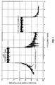
- Fig. 1 An example of this problem is shown in Fig. 1 . Note that positive frequency bands in the Fig. represent frequencies to the right of the transmission carrier center and negative frequency bands represent frequencies to the left of the transmission carrier center.
- the first type of interferences which are generally caused by phase noise, frequency offset and channel time-selectivity, affects adjacent band signals. However, the interference powers generally decay with frequency separation.
- the second type of interferences which are generally caused by In-phase and Quadrature (IQ) imbalances, affects signals at the mirror frequency bands.
- IQ In-phase and Quadrature
- the loss of orthogonality means the signal quality of UEs scheduled in parallel in the frequency domain can be severely degraded.
- the problems become particularly acute when the received signal strengths, such as may be expressed in a determination of received (signal) power densities, from different UEs differ significantly.
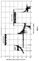
- Fig. 2 illustrates that circumstance.
- the signals as received at the network receiver from user B and user C are 30 dB and 20 dB weaker than that of user A, respectively.
- the overall carrier power to interference ratio (C/I) for user B is around 0 dB since its signal is affected by Type-I interference from user A.
- the overall C/I ratio of user C is less than 5 dB since its signal is affected by Type-II interference from user A. Because of the low C/I ratio, neither user B nor C can transmit at high data rates.
- Fig. 2 For uplink transmissions, the situation depicted in Fig. 2 typically arises when the path gains of different users differ dramatically.
- Existing solutions to mitigate this near-far problem include, in the context of CDMA-based systems, uplink power control used to equalize received powers of non-orthogonal codes.
- WLAN wireless local area network
- frequency division multiplexing is completely avoided by dedicating the whole frequency band to a single user at any given time.
- GSM Global System contexts, the transmission bandwidth is fixed and, hence, a single analog narrow-band filter can be applied to the transmitted signal to reduce out-of-band interference.
- uplink power control aimed at equalizing received power is useful in systems providing fixed-rate services, such as circuit-switched voice services.
- receive power equalization may not be efficient, at least not standing alone, because there generally will not be any fixed SNR target associated with a particular date rate.
- the system capacity and UE throughput can be generally optimized if UEs experiencing good channel conditions can transmit at higher power and, hence, higher data rates.
- the R1-050813 (UL interference control considerations) and R1-060298 (“Uplink inter cell interference mitigation”) working group documents promulgated by the 3GPP TSG RAN WG1 suggest a particular frequency allocation scheme. In essence, UEs are assigned to frequency bands based on a signal strength/signal-to-noise-ratio (SNR) ranking. However, the proposed arrangement provides no protection against Type-II interference defined above in the context of OFDM subcarriers.
- WO 2005/096533 A1 describes a method and apparatus for communicating in an OFDM system whereby subcarriers of the OFDM system are multiplexed between at least a first and a second transmit antenna.
- the subcarriers are separated between the at least two transmit antennas so that a subcarrier and a mirror subcarrier are not transmitted on the same transmit antenna and that adjacent subcarriers on the same antenna are at least two subcarrier frequency bandwidths apart.
- UEs user equipments
- TTI transmission time interval
- QoS quality of service
- UEs with significantly different received signal power densities are scheduled to transmit in different scheduling intervals.
- Complementary power control may be jointly included in such scheduling, such as by directly or indirectly controlling the transmit power of UEs individually or in groups to reduce differences in the received signal power densities of the UEs being scheduled.
- a method of scheduling user equipments (UEs) in a wireless communication network comprises determining received signal power densities for a plurality of UEs to be scheduled, and allocating UEs to scheduling intervals based on a sorting of their received signal power densities such that UEs in the same scheduling interval have similar received signal power densities.
- the method further includes assigning UEs in the same scheduling interval to mirror frequency bands within an available frequency spectrum according to the sorting of their received signal power densities.
- OFDM Orthogonal Frequency Division Multiplexing
- the difference between received signal power densities for each pair of UEs being assigned to mirror frequencies can be evaluated against an allowable difference.
- One or more embodiments presented herein directly or indirectly adjusts the received signal power density of one or both UEs in any pair of UEs where the difference in their received signal power densities exceeds the allowable difference.
- One adjustment approach involves explicitly controlling the transmit power of one or both such UEs.
- a network entity managing the scheduling such as a base station, may directly or indirectly signal desired received signal power densities to the UEs scheduled for the same scheduling interval, to reduce such differences and thereby better mitigate intra-cell interference between the UEs.
- Fig. 3 illustrates a wireless communication network 8, e.g., an WCDMA/LTE network, that includes a network entity 10, e.g., a base station 10, which includes one or more processing circuits 12.
- the processing circuits 12 are configured to schedule a plurality of user equipments (UEs) 14 (shown as UEs 1..N) in a manner that mitigates intra-cell interference.
- UEs user equipments
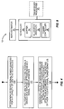
- Fig. 4 illustrates a processing method that may be carried out by the processing circuits 12 of the base station 10, according to one embodiment of UE scheduling and/or power control as taught herein. It should be understood that the method is not necessarily limited to the illustrated processing sequence, and some processing steps may be performed together or otherwise in an interrelated fashion. Further, the illustrated processing sequence may be conducted on an ongoing basis, possibly as part of a larger set of communication processing operations carried out at the base station 10.
- the illustrated processing begins with determining the received signal power densities for a plurality of UEs 14 to be scheduled (Step 100). For example, the base station 10 may identify all active-state UEs 14 being supported by it. In any case, processing continues with allocating UEs 14 to scheduling intervals-e.g., transmission time intervals (TTIs) in a WCDMA/LTE embodiment-based on a sorting of their received signal power densities (Step 102). Processing continues or otherwise further includes assigning UEs 14 in the same scheduling interval to mirror frequency bands within an available frequency spectrum according to the sorting of their received signal power densities (Step 104).
- TTIs transmission time intervals
- this step may comprise assigning pairs of the UEs 14 sorted in rank order of their received signal power densities to consecutive mirror frequency bands within an available frequency spectrum.
- assigning these pairs of the UEs 14 comprises, in at least one embodiment, assigning pairs of UEs 14 that are adjacent in the rank order of their received signal power densities to mirror frequency positions in a set of orthogonal frequency division multiplexing (OFDM) sub-carriers.
- OFDM orthogonal frequency division multiplexing
- Fig. 5 illustrates a set of OFDM subcarriers spanning a given frequency spectrum, wherein the illustrated set of subcarriers may be considered as including a center frequency having mirrored frequency tones on either side.
- Fig. 6 illustrates UEs 1..N, which are sorted in rank order according to their received signal power densities.
- assigning pairs of UEs 14 that are adjacent in the rank order of their received signal power densities to mirror frequency positions in a set of OFDM sub-carriers includes assigning a highest ranked pair of UEs (i.e., the rightmost UEs N and N-1 in Fig.
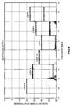
- Figs. 7 and 8 illustrate two scheduling intervals, denoted as TTI 1 and TT2, respectively.
- TTI 1 and TT2 two scheduling intervals.
- some plurality of UEs 14 are identified as Users 1..11, and that a first subset of these UEs 14 were assigned to TTI 1 and a second subset were assigned to TTI 2. More particularly, one sees the rank ordering arrangement reflected in the pairwise assignments of User 1/User 2, User 3/User 4, etc., in TTI 1, and User 6/User 7, User 8/User 9, etc., in TTI 2.
- one or more embodiments of the scheduling method comprise scheduling UEs 14 in a wireless communication network 8, based on determining received signal power densities for a plurality of UEs 14 to be scheduled, allocating the UEs 14 to scheduling intervals based on a sorting of their received signal power densities, and assigning UEs 14 in the same scheduling interval to mirror frequency bands within an available frequency spectrum according to the sorting of their received signal power densities.
- the above method sorts the UEs 14 by their received signal power densities, and uses that sort order to assign a first set (subgroup) of the UEs 14 to a first scheduling interval, with the remaining UEs 14 allocated to one or more subsequent scheduling intervals.
- the whole process is dynamic in the context of changing numbers of UEs 14 subject to scheduling, changing reception conditions, QoS considerations, etc.
- the method may include signaling a desired received signal power density for UEs 14 in the same scheduling interval.
- Such embodiments may include determining the desired received signal power density on a scheduling interval basis as a function of the received signal power densities of the UEs allocated to each given scheduling interval. (Thus, a different desired received signal power density may be signaled for different scheduling intervals, reflecting the different values of the received signal power densities estimated for the particular ones of the UEs 14 allocated to each such scheduling interval.)
- the desired received signal power density for a given scheduling interval is determined as the sum of a defined, allowable difference between received signal power densities for UEs 14 in any given scheduling interval and a minimum received signal power density of those UEs 14 in the given scheduling interval, or as an average of the received signal power densities of those UEs 14 in the given scheduling interval.
- the allowable difference may be defined by default value, or may be determined dynamically.
- signaling the desired received signal power density for UEs 14 in the same scheduling interval may be done on a conditional basis, based on determining whether a difference between maximum and minimum received signal power densities for the UEs scheduled in a given scheduling interval exceeds an allowable difference. That is, the particular UEs 14 assigned to a given scheduling interval may have a difference (max-min) of received signal power densities that is below the allowable difference, in which case there is no need to signal a desired (target) received signal power density.
- processing in one or more embodiments includes determining whether a difference between maximum and minimum received signal power densities for the UEs 14 scheduled in a given scheduling interval exceeds an allowable difference and, if so, signaling one or more of the UEs 14 to adjust one or more of their transmission parameters bearing on their received signal power densities.
- Such transmission parameters can include transmit powers and/or signal bandwidths.
- Signal bandwidth adjustments for a given UE 14 can be used to alter received signal power density. For example, density is lowered for a given transmit power level and path gain by expanding the signal bandwidth, and raised by decreasing the signal bandwidth.
- allocating UEs 14 to scheduling intervals based on a sorting of their received signal power densities comprises sorting UEs 14 by their received signal power densities and allocating UEs 14 from consecutive sorted positions to the scheduling interval until the scheduling interval is fully allocated. At least one embodiment includes ranking the UEs 14 to be scheduled according to their received signal power densities and, for a given scheduling interval, allocating UEs 14 based on their rank order to the given scheduling interval until the given scheduling interval is fully allocated.
- assigning UEs 14 in the same scheduling interval to mirror frequency bands within an available frequency spectrum according to the sorting of their received signal power densities comprises assigning pairs of the UEs 14 sorted in rank order of their received signal power densities to consecutive mirror frequency bands within an available frequency spectrum.
- Such operations may comprise assigning pairs of UEs 14 that are adjacent in the rank order of their received signal power densities to mirror frequency positions in a set of orthogonal frequency division multiplexing (OFDM) sub-carriers.
- OFDM orthogonal frequency division multiplexing
- the method may include assigning a highest ranked pair of UEs 14 to an outermost pair of mirror frequency positions and assigning next highest ranked pairs of UEs 14 to consecutive mirror frequency positions moving inward toward a center frequency of the OFDM sub-carriers:
- Fig. 9 illustrates functional circuit elements for one embodiment of the processing circuits 12.
- the processing circuits 12 may comprise hardware, software, or any combination thereof.
- the processing circuits 12 include one or more general or special purpose microprocessors and/or digital signal processors that are programmed to carry out operations corresponding to the above-described method steps.
- Such instructions may be embodied as one or more computer programs comprising stored program instructions in a storage element (e.g., memory).
- the processing circuits 12 comprises a received signal power density estimator 30 (illustrated as "RSPD" estimator).
- the received signal power density estimator 30 may receive calculation information from other elements within the BS 10, such as estimated, known, or default values to use for the calculation of the received signal power densities.
- the base station 10 generally includes channel estimation circuits (not shown), which may provide values related to the path gain variables g u .
- the processing circuits 12 further include a scheduler 32, which may include (or is associated with) a sorter 34 and an allocator/assigner 36, and which may further include a power controller 38.
- the sorter 34 sorts the UEs 14 to be scheduled in rank order of their received signal power densities as estimated by the RSDP estimator 30, and the allocator/assigner 36 allocates UEs 14 to respective scheduling intervals based on the sorted order, as described above.
- the power controller 38 may initiate or otherwise cause power signaling from the base station 10 to one or more of the UEs 14, to reduce differences between the received signal power densities of UEs 14 in the same scheduling interval, e.g., between pairs of UEs 14 that are pairwise assigned to mirror frequencies in a set of OFDM tones.
- the base station 10 includes transceiver resources 40 for wirelessly communicating with the UEs 14 on uplink and downlink communication channels.
- the base station 10 may include other elements, such as backhaul/sidehaul interfaces, etc., which are not illustrated and which are not germane to this discussion.
- the scheduling (and power control) methods described herein provide a number of advantages and features.
- one such advantage is that individual UEs 14 in favorable situations may get higher bit-rates than with conventional scheduling approaches. In turn, higher bit rates improve system capacity.
- the modulation quality (e.g. EVM) of the transmitted and received signals can be maintained at acceptable levels, thereby preventing excessive demodulation losses at the base station 10.
- Fig. 10 illustrates one embodiment of the scheduling method presented herein.
- a representative scheduling/power control method involves a number of processing steps that are detailed below, and it should be understood that not all such steps are necessarily limited to the illustrated sequence, and some steps may be performed jointly or concurrently.
- the path gain g u , maximum transmit power P max u , and signal bandwidth W u of each user are determined (Step 112).
- the maximum achievable received signal power density is then determined-see Eq. (1)-from these values for each of the UEs to be scheduled (Step 114).
- Step 116 determining a maximum difference in received signal power densities, dD max , to be allowed for UEs in the same scheduling interval. Then, beginning with the UE with the highest achievable received signal power density, UEs are allocated in a first TTI, until that TTI is fully allocated (Step 118).
- the frequency assignments of users in the same scheduling interval may follow those details presented in the context of Figs. 5 and 6 , for example. That is, users are pair-wise allocated to mirror frequencies within the available spectrum until the scheduling interval is fully allocated (Step 120).
- the received signal power densities of one or more of the users is adjusted directly or indirectly (Step 128).
- the processing circuits 12 may be configured to cause the base station 10 to set the transmit power levels of users with high received signal power densities to values below their maximum, i.e., P u ⁇ P max u .
- "high” simply connotes one or more of the UEs 14 within the given scheduling interval being considered that have received signal power densities above those of the remaining UEs 14 scheduled in that interval.
- the processing circuits 12 may be configured to cause the base station 10 to adjust the signal bandwidths of one or more of the scheduled users. For example, one or more users having relatively low received signal power densities may have their signal bandwidths decreased. Conversely, one or more users having relatively higher received signal power densities may have their signal bandwidths increased.
- the base station 10 may signal an "allowed transmit power,” such as by signaling the absolute value of the transmit power to be used, or by signaling an offset relative to the UE's maximum transmit power.
- the receiver circuits 12 may be configured to compute a desired received signal power density (e.g., a target value), such that the base station 10 signals the desired received signal power density at least to the group of UEs 14 to be served in the same scheduling interval.
- a desired received signal power density e.g., a target value
- the desired received signal power density may change from scheduling interval to scheduling interval, because of changes in the received signal power densities (relative or absolute) of the UEs 14 being allocated to the different scheduling intervals.
- D target min D u + dD max
- ⁇ D u ⁇ is the set of maximum power spectral densities of users scheduled in the same scheduling interval (e.g., the same TTI).
- other rules are possible to estimate the target received power spectral density, such as the average of ⁇ D u ⁇ .
- each UE 14 can estimate its path gain g u based on receiving downlink reference symbols, e.g., pilot information.
- CPICH Common Pilot Channel
- the CPICH RSCP is also reported to the network 8 (base station 10), which uses it for various Radio Resource Management (RRM) functions, such as handovers, etc.
- RRM Radio Resource Management
- the above embodiment of signaling the desired received signal power density may be implemented by multicasting of the desired value on a scheduling interval basis, for use by the groups of UEs scheduled in same scheduling interval. Signaling overheads can be further reduced by signaling the desired received signal power density as an offset from some maximum or minimum predefined level.
- both the received signal power densities and received signal quality (SNR) are known for each of the UEs 14 subject to scheduling.
- SNR received signal quality
- TTI scheduling interval
- the typical measurement entity may refer to a "cell" or other defined coverage area within a cell/sector communication environment.
- the scheduling method(s) presented herein may consider user bitrate (individual or aggregate) as an adaptation objective when considering whether (and by how much) to adjust the received signal power densities of UEs 14. For example, the maximum number of bits received per TTI can be targeted. Alternatively some fairness between UEs 14 can be achieved. Of course, QoS and other constraints also may be included for consideration in the determining of whether and by how much received signal power densities are adjusted for individual or groups of UEs 14.
- one or more embodiments of the scheduling method presented herein may be practiced without the base station 10 necessarily having access to all of the information needed to determine the received signal power densities for the UEs 14 subject to scheduling, such as shown in Eq. (1).
- scheduling as taught herein can be applied using incremental controls and commands that are supported by currently available information.
- the scheduling algorithm at the base station 10 can calculate the expected impact on interference levels if it decides to command the UE 16 to increase transmission power by X dB, or to change the amount of assigned frequency band by Y %.
- the methods presented herein can also be used to carry out combined scheduling and power control in the downlink, where the transmitted power spectral density of the users scheduled during the same interval should be within a certain maximum range ( dD max ). Doing so ensures that a base station transmitter does not cause excessive EVM, which in turn helps guarantee adequate modulation quality of the transmitted signal at the base station. When compared to the uplink case, one may consider that the transmitted power spectral density of all users scheduled during the same scheduling interval should be maintained within an allowed range. Also, for downlink implementations, control signaling regarding adjustments of received signal power densities to one or more UEs 14 is not needed as the base station 10 originates the transmitted signals.
- scheduling as taught herein may be carried out on a combined multi-cell (sector) basis.
- neighboring base stations 10 may schedule UEs 14 in neighboring sectors as a function of their received signal power densities, to mitigate intra- and inter-cell interference.
- Such combined scheduling may be done on the uplink and/or downlink.
Landscapes
- Engineering & Computer Science (AREA)
- Signal Processing (AREA)
- Computer Networks & Wireless Communication (AREA)
- Quality & Reliability (AREA)
- Mobile Radio Communication Systems (AREA)
Claims (11)
- Verfahren zum Terminieren von Benutzerausrüstungen, UEs, (14) in einem Orthogonal-Frequenzmultiplex- bzw. OFDM-Drahtlos-Kommunikationsnetzwerk, umfassend:Bestimmen (100) von Empfangssignalleistungsdichten für eine Vielzahl von UEs (14), die zu terminieren sind;Zuteilen (102) von UEs (14) zu Terminierungsintervallen basierend auf einer Sortierung ihrer Empfangssignalleistungsdichten, wobei Zuteilen von UEs (14) zu Terminierungsintervallen basierend auf einer Sortierung ihrer Empfangssignalleistungsdichten umfasst, UEs (14) nach ihren Empfangssignalleistungsdichten zu sortieren und UEs (14) von aufeinanderfolgenden sortierten Positionen dem Terminierungsintervall zuzuteilen, bis das Terminierungsintervall vollständig zugeteilt ist; undZuweisen (104) von zugeteilten UEs (14) in dem gleichen Terminierungsintervall zu Spiegelfrequenzbändern innerhalb eines verfügbaren Frequenzspektrums gemäß der Sortierung ihrer Empfangssignalleistungsdichten, wobei Zuweisen zugeteilter UEs (14) in dem gleichen Terminierungsintervall zu Spiegelfrequenzbändern innerhalb eines verfügbaren Frequenzspektrums gemäß der Sortierung ihrer Empfangssignalleistungsdichten umfasst, Paare der UEs (14), die in der Rangordnung ihrer Empfangssignalleistungsdichten aneinanderliegend sind, jeweiligen Spiegelfrequenzbändern in Bezug auf eine Mittenfrequenz eines Hilfsträgers innerhalb eines verfügbaren Frequenzspektrums zuzuweisen, wobei aufeinanderfolgende Paare der zugeteilten UEs aufeinanderfolgenden Spiegelfrequenzbändern zugewiesen werden.
- Verfahren nach Anspruch 1, ferner umfassend, eine gewünschte Empfangssignalleistungsdichte für UEs (14) in dem gleichen Terminierungsintervall zu signalisieren.
- Verfahren nach Anspruch 2, ferner umfassend, die gewünschte Empfangssignalleistungsdichte auf einer Terminierungsintervallbasis als eine Funktion der Empfangssignalleistungsdichten der UEs (14), die jedem gegebenen Terminierungsintervall zugeteilt wurden, zu bestimmen.
- Verfahren nach Anspruch 1, wobei Zuteilen von UEs (14) zu Terminierungsintervallen basierend auf der Sortierung ihrer Empfangssignalleistungsdichten umfasst, die UEs (14), die zu terminieren sind, gemäß ihren Empfangssignalleistungsdichten zu ordnen und, für ein gegebenes Terminierungsintervall, UEs (14) basierend auf ihrer Rangordnung dem gegebenen Terminierungsintervall zuzuteilen, bis das gegebene Terminierungsintervall vollständig zugeteilt ist.
- Verfahren nach Anspruch 1, ferner umfassend, für ein beliebiges gegebenes Terminierungsintervall, zu bestimmen, ob eine Differenz zwischen minimalen und maximalen einen der Empfangssignalleistungsdichten für UEs (14), die für dieses gegebene Terminierungsintervall terminiert wurden, eine zulässige Differenz übersteigt, und, falls ja, einer oder mehreren dieser UEs (14) zu signalisieren, einen oder mehrere ihrer Übertragungsparameter anzupassen, um die Differenz zu reduzieren.
- Verfahren nach Anspruch 1, wobei Bestimmen von Empfangssignalleistungsdichten für eine Vielzahl von UEs (14), die zu terminieren sind, umfasst, für jede solche UE (14) eine erreichbare Empfangssignalleistungsdichte als eine Funktion einer maximalen Übertragungsleistung der UE (14), einer Wegverstärkung der UE (14) und einer Signalbandbreite der UE (14) zu bestimmen.
- Basisstation (10), konfiguriert zum Terminieren von Benutzerausrüstungen, UEs, (14) für Betrieb in einem Orthogonalfrequenzmultiplex- bzw. OFDM-Drahtlos-Kommunikationsnetzwerk, wobei die Basisstation (10) eine oder mehrere Verarbeitungsschaltungen (12) umfasst, konfiguriert zum:Bestimmen (100) von Empfangssignalleistungsdichten für eine Vielzahl von UEs (14), die zu terminieren sind;Zuteilen (102) von UEs (14) zu Terminierungsintervallen basierend auf einer Sortierung ihrer Empfangssignalleistungsdichten, wobei die eine oder mehreren Verarbeitungsschaltungen (12) der Basisstation (10) konfiguriert sind zum Zuteilen von UEs (14) zu Terminierungsintervallen basierend auf einer Sortierung ihrer Empfangssignalleistungsdichten durch Sortieren von UEs (14) nach ihren Empfangssignalleistungsdichten und Zuteilen von UEs (14) von aufeinanderfolgenden sortierten Positionen zu dem Terminierungsintervall, bis das Terminierungsintervall vollständig zugeteilt ist; undZuweisen von zugeteilten UEs (14) in dem gleichen Terminierungsintervall zu Spiegelfrequenzbändern innerhalb eines verfügbaren Frequenzspektrums gemäß der Sortierung ihrer Empfangssignalleistungsdichten, wobei die eine oder mehreren Verarbeitungsschaltungen (12) der Basisstation (10) konfiguriert sind zum Zuweisen zugeteilter UEs (14) in dem gleichen Terminierungsintervall zu Spiegelfrequenzbändern innerhalb eines verfügbaren Frequenzspektrums gemäß der Sortierung ihrer Empfangssignalleistungsdichten durch Zuweisen von Paaren der UEs (14), die in der Rangordnung ihrer Empfangssignalleistungsdichten aneinanderliegend sind, zu jeweiligen Spiegelfrequenzbändern in Bezug auf eine Mittenfrequenz eines Hilfsträgers innerhalb eines verfügbaren Frequenzspektrums, wobei aufeinanderfolgende Paare der zugeteilten UEs aufeinanderfolgenden Spiegelfrequenzbändern zugewiesen werden.
- Basisstation (10) nach Anspruch 7, wobei die eine oder mehreren Verarbeitungsschaltungen (12) eine Empfangssignalleistungsdichte-Schätzvorrichtung (30), konfiguriert zum Bestimmen der Empfangssignalleistungsdichten für die Vielzahl von UEs (14), die zu terminieren sind, und eine Terminierungsvorrichtung (32), konfiguriert zum Zuteilen der UEs (14) zu Terminierungsintervallen basierend auf der Sortierung ihrer Empfangssignalleistungsdichten und Zuweisen von UEs (14) in der gleichen Terminierung zu Spiegelfrequenzbändern innerhalb des verfügbaren Frequenzspektrums gemäß der Sortierung ihrer Empfangssignalleistungsdichten, enthalten.
- Basisstation nach Anspruch 7, wobei die eine oder mehreren Verarbeitungsschaltungen (12) der Basisstation (10) konfiguriert sind, eine gewünschte Empfangssignalleistungsdichte für UEs (14) in dem gleichen Terminierungsintervall zu signalisieren.
- Basisstation nach Anspruch 7, wobei die eine oder mehreren Verarbeitungsschaltungen (12) der Basisstation (10) konfiguriert sind, UEs (14) zu Terminierungsintervallen basierend auf der Sortierung ihrer Empfangssignalleistungsdichten durch Ordnen der UEs (14), die zu terminieren sind, gemäß ihrer Empfangssignalleistungsdichten zuzuteilen und, für ein gegebenes Terminierungsintervall, durch Zuteilen der UEs (14) basierend auf ihrer Rangordnung dem gegebenen Terminierungsintervall, bis das gegebene Terminierungsintervall vollständig zugeteilt ist.
- Basisstation (10) nach Anspruch 7, wobei die eine oder mehreren Verarbeitungsschaltungen (12) der Basisstation (10) konfiguriert sind, für ein beliebiges gegebenes Terminierungsintervall zu bestimmen, ob eine Differenz zwischen minimalen und maximalen einen der Empfangssignalleistungsdichten für UEs (14), die für dieses gegebene Terminierungsintervall terminiert wurden, eine zulässige Differenz übersteigt, und, falls ja, einer oder mehreren dieser UEs (14) zu signalisieren, einen oder mehrere ihrer Übertragungsparameter anzupassen, um die Differenz zu reduzieren.
Applications Claiming Priority (2)
| Application Number | Priority Date | Filing Date | Title |
|---|---|---|---|
| US74619606P | 2006-05-02 | 2006-05-02 | |
| PCT/SE2007/050294 WO2007126385A2 (en) | 2006-05-02 | 2007-04-30 | I/q imbalance compensation using scheduling |
Publications (3)
| Publication Number | Publication Date |
|---|---|
| EP2020132A2 EP2020132A2 (de) | 2009-02-04 |
| EP2020132A4 EP2020132A4 (de) | 2014-07-16 |
| EP2020132B1 true EP2020132B1 (de) | 2016-07-27 |
Family
ID=38655934
Family Applications (1)
| Application Number | Title | Priority Date | Filing Date |
|---|---|---|---|
| EP07748455.8A Active EP2020132B1 (de) | 2006-05-02 | 2007-04-30 | Verfahren und vorrichtung zur benutzergeräteverwaltung auf störungsbasis in einem drahtlosen kommunikationsnetz |
Country Status (5)
| Country | Link |
|---|---|
| US (1) | US20070259681A1 (de) |
| EP (1) | EP2020132B1 (de) |
| JP (1) | JP4981127B2 (de) |
| CN (1) | CN101455045B (de) |
| WO (1) | WO2007126385A2 (de) |
Families Citing this family (21)
| Publication number | Priority date | Publication date | Assignee | Title |
|---|---|---|---|---|
| US10084627B2 (en) * | 2006-07-10 | 2018-09-25 | Qualcomm Incorporated | Frequency hopping in an SC-FDMA environment |
| JP4882775B2 (ja) * | 2007-02-09 | 2012-02-22 | 富士通株式会社 | 無線端末の通信制御方法及び無線端末 |
| FR2916919B1 (fr) * | 2007-05-31 | 2009-09-04 | Commissariat Energie Atomique | Terminal radio opportuniste |
| US8139527B2 (en) * | 2007-12-19 | 2012-03-20 | Wi-Lan, Inc. | Wireless system with reduced effect of IQ imbalance |
| JP5115273B2 (ja) * | 2008-03-28 | 2013-01-09 | 富士通株式会社 | 無線通信システム、無線基地局装置、マルチサービス管理装置 |
| JPWO2009142025A1 (ja) * | 2008-05-23 | 2011-09-29 | パナソニック株式会社 | 無線通信移動局装置およびリソースエレメント分散配置方法 |
| US20110211549A1 (en) * | 2008-11-12 | 2011-09-01 | Agency For Science, Technology And Research | Multiple access communication system |
| WO2010084801A1 (ja) * | 2009-01-26 | 2010-07-29 | ソニー株式会社 | 通信制御方法、通信装置、及びプログラム |
| JP2010226440A (ja) * | 2009-03-24 | 2010-10-07 | Nec Corp | 送信電力制御方法及び無線通信システム |
| US8848698B2 (en) * | 2011-10-22 | 2014-09-30 | Lg Electronics Inc. | Scheduling method in multiple access system and apparatus using the same |
| GB2502108B (en) * | 2012-05-16 | 2014-10-15 | Canon Kk | Reception quality assessment |
| CN103581075B (zh) * | 2012-07-24 | 2016-12-21 | 瑞昱半导体股份有限公司 | 降低无线通信系统的信号不平衡的方法 |
| CN103036846B (zh) * | 2012-12-27 | 2015-09-09 | 上海创远仪器技术股份有限公司 | 应用于通信系统接收机的i/q不平衡补偿控制方法 |
| US8897829B2 (en) * | 2013-02-01 | 2014-11-25 | Nvidia Corporation | Controlling transmit power in a wireless device |
| CN104244335B (zh) * | 2013-06-13 | 2019-12-10 | 索尼公司 | 干扰协调方法、干扰协调装置以及测量装置 |
| WO2015172802A1 (en) | 2014-05-12 | 2015-11-19 | Telefonaktiebolaget L M Ericsson (Publ) | Scheduling in wireless local area networks |
| CN107659524B (zh) * | 2016-07-25 | 2022-01-07 | 中兴通讯股份有限公司 | 信号处理方法及装置 |
| EP3280106A1 (de) * | 2016-08-05 | 2018-02-07 | Ntt Docomo, Inc. | Verfahren und vorrichtung zur übertragung eines signals und verfahren und vorrichtung zum empfangen eines signals |
| US10237835B1 (en) * | 2017-11-06 | 2019-03-19 | T-Mobile Usa, Inc. | Temporal power control system and method |
| US11038639B1 (en) * | 2019-10-18 | 2021-06-15 | T-Mobile Innovations Llc | Performing MU-MIMO based on bandwidth parts |
| CN113811012B (zh) * | 2020-06-16 | 2024-03-29 | 华为技术有限公司 | 调度方法、装置及系统、存储介质 |
Family Cites Families (13)
| Publication number | Priority date | Publication date | Assignee | Title |
|---|---|---|---|---|
| US6272325B1 (en) * | 1995-07-13 | 2001-08-07 | Globalstar L.P. | Method and apparatus for considering user terminal transmitted power during operation in a plurality of different communication systems |
| US20020127982A1 (en) * | 2001-03-07 | 2002-09-12 | Nokia Mobile Phones Ltd | Mobile station receiver operable for both single and multi-carrier reception |
| US7092683B2 (en) * | 2003-04-01 | 2006-08-15 | Matsushita Electric Industrial Co., Ltd. | Transmission circuit |
| CN1299454C (zh) * | 2003-06-18 | 2007-02-07 | 清华大学 | 用于ofdm下保障实时业务服务质量的调度方法 |
| DE10328570B4 (de) * | 2003-06-25 | 2005-08-25 | Infineon Technologies Ag | Verfahren zur Reduzierung der Strahlungsbelastung durch ein Mobilfunkterminal mit gerichteter Abstrahlung und Mobilfunkterminal mit gerichteter Abstrahlung |
| US20050095578A1 (en) * | 2003-10-31 | 2005-05-05 | Koller Manfred R. | Method and apparatus for cell permeabilization |
| US7046617B2 (en) * | 2004-03-22 | 2006-05-16 | Motorola, Inc. | Method and apparatus for an enhanced OFDM system |
| US7437164B2 (en) * | 2004-06-08 | 2008-10-14 | Qualcomm Incorporated | Soft handoff for reverse link in a wireless communication system with frequency reuse |
| WO2006004968A2 (en) * | 2004-06-30 | 2006-01-12 | Neocific, Inc. | Methods and apparatus for power control in multi-carrier wireless systems |
| US20070004465A1 (en) * | 2005-06-29 | 2007-01-04 | Aris Papasakellariou | Pilot Channel Design for Communication Systems |
| US7551693B2 (en) * | 2005-11-29 | 2009-06-23 | Coppergate Communications Ltd. | High-frequency HomePNA |
| US20070173260A1 (en) * | 2006-01-23 | 2007-07-26 | Love Robert T | Wireless communication network scheduling |
| WO2007091235A2 (en) * | 2006-02-09 | 2007-08-16 | Altair Semiconductor Ltd. | Low peak-to-average power ratio transmission in frequency-division multiple access systems |
-
2007
- 2007-04-27 US US11/741,083 patent/US20070259681A1/en not_active Abandoned
- 2007-04-30 WO PCT/SE2007/050294 patent/WO2007126385A2/en not_active Ceased
- 2007-04-30 JP JP2009509495A patent/JP4981127B2/ja not_active Expired - Fee Related
- 2007-04-30 EP EP07748455.8A patent/EP2020132B1/de active Active
- 2007-04-30 CN CN2007800157044A patent/CN101455045B/zh active Active
Also Published As
| Publication number | Publication date |
|---|---|
| WO2007126385A3 (en) | 2008-01-03 |
| JP2009535970A (ja) | 2009-10-01 |
| EP2020132A4 (de) | 2014-07-16 |
| CN101455045A (zh) | 2009-06-10 |
| US20070259681A1 (en) | 2007-11-08 |
| JP4981127B2 (ja) | 2012-07-18 |
| CN101455045B (zh) | 2013-02-06 |
| WO2007126385A2 (en) | 2007-11-08 |
| EP2020132A2 (de) | 2009-02-04 |
Similar Documents
| Publication | Publication Date | Title |
|---|---|---|
| EP2020132B1 (de) | Verfahren und vorrichtung zur benutzergeräteverwaltung auf störungsbasis in einem drahtlosen kommunikationsnetz | |
| US8831120B2 (en) | Adaptive subcarrier allocation to a mobile terminal in a multi cell FDM or OFDM network | |
| US8675563B2 (en) | Method and apparatus for interference control in a multi-cell communication system | |
| US8948807B2 (en) | Coordinated power boost and power back-off | |
| EP1997334B1 (de) | Messunterstützte dynamische frequenzwiederverwendung in mobilfunknetzen | |
| EP2245757B1 (de) | Verfahren und system zur minderung von störungen zwischen zellen | |
| JP4939625B2 (ja) | セルラ無線通信システムにおける干渉均衡化のための、チャネル割り当て中の送信電力レベル設定 | |
| EP2460378B1 (de) | Verfahren, vorrichtung und computerlesbares medium zur reduzierung von selbstinduzierten interferenzen eines benutzergeräts in kommunikationssystemen | |
| US8023989B2 (en) | Coordinated power boost and power back-off | |
| US8412243B2 (en) | Power control method and apparatus for inter-cell interference removal | |
| CN102239717A (zh) | 在无线通信网络中优化带宽分配的方法 | |
| KR20090123880A (ko) | 무선 통신 시스템에서의 동일채널 간섭의 특징화 | |
| KR20060038131A (ko) | Fh-ofdma 방식을 사용하는 통신 시스템에서상향링크 스케줄링 방법 | |
| EP2036363A2 (de) | Verfahren und vorrichtung für upling-leistungsregelung in einem frequenzmultiplex-kommunikationssystem mit mehrfachzugriff | |
| US8565161B2 (en) | Adaptive frequency reuse scheme | |
| EP1761095A1 (de) | Basisstationsvorrichtung und drahtloses kommunikationsverfahren | |
| WO2012146278A1 (en) | Apparatus and method for communication with a number of user equipments using ofdma | |
| Penttinen et al. | LTE‐A Radio Network | |
| Rao et al. | Opportunistic subcarrier allocation scheme for FFR-aided LTE networks | |
| HK1145905A (en) | A method and system for mitigating inter-cell interference | |
| HK1145905B (en) | A method and system for mitigating inter-cell interference |
Legal Events
| Date | Code | Title | Description |
|---|---|---|---|
| PUAI | Public reference made under article 153(3) epc to a published international application that has entered the european phase |
Free format text: ORIGINAL CODE: 0009012 |
|
| 17P | Request for examination filed |
Effective date: 20081201 |
|
| AK | Designated contracting states |
Kind code of ref document: A2 Designated state(s): AT BE BG CH CY CZ DE DK EE ES FI FR GB GR HU IE IS IT LI LT LU LV MC MT NL PL PT RO SE SI SK TR |
|
| AX | Request for extension of the european patent |
Extension state: AL BA HR MK RS |
|
| DAX | Request for extension of the european patent (deleted) | ||
| A4 | Supplementary search report drawn up and despatched |
Effective date: 20140613 |
|
| RIC1 | Information provided on ipc code assigned before grant |
Ipc: H04L 27/26 20060101AFI20140606BHEP Ipc: H04W 72/12 20090101ALI20140606BHEP Ipc: H04L 27/36 20060101ALI20140606BHEP Ipc: H04L 5/00 20060101ALI20140606BHEP |
|
| GRAP | Despatch of communication of intention to grant a patent |
Free format text: ORIGINAL CODE: EPIDOSNIGR1 |
|
| INTG | Intention to grant announced |
Effective date: 20160311 |
|
| RIC1 | Information provided on ipc code assigned before grant |
Ipc: H04L 27/26 20060101AFI20160229BHEP Ipc: H04L 27/36 20060101ALI20160229BHEP Ipc: H04W 72/12 20090101ALI20160229BHEP Ipc: H04L 5/00 20060101ALI20160229BHEP |
|
| GRAS | Grant fee paid |
Free format text: ORIGINAL CODE: EPIDOSNIGR3 |
|
| GRAA | (expected) grant |
Free format text: ORIGINAL CODE: 0009210 |
|
| AK | Designated contracting states |
Kind code of ref document: B1 Designated state(s): AT BE BG CH CY CZ DE DK EE ES FI FR GB GR HU IE IS IT LI LT LU LV MC MT NL PL PT RO SE SI SK TR |
|
| REG | Reference to a national code |
Ref country code: GB Ref legal event code: FG4D |
|
| REG | Reference to a national code |
Ref country code: CH Ref legal event code: EP |
|
| REG | Reference to a national code |
Ref country code: AT Ref legal event code: REF Ref document number: 816595 Country of ref document: AT Kind code of ref document: T Effective date: 20160815 |
|
| REG | Reference to a national code |
Ref country code: IE Ref legal event code: FG4D |
|
| REG | Reference to a national code |
Ref country code: DE Ref legal event code: R096 Ref document number: 602007047178 Country of ref document: DE |
|
| REG | Reference to a national code |
Ref country code: LT Ref legal event code: MG4D |
|
| REG | Reference to a national code |
Ref country code: NL Ref legal event code: MP Effective date: 20160727 |
|
| REG | Reference to a national code |
Ref country code: AT Ref legal event code: MK05 Ref document number: 816595 Country of ref document: AT Kind code of ref document: T Effective date: 20160727 |
|
| PG25 | Lapsed in a contracting state [announced via postgrant information from national office to epo] |
Ref country code: LT Free format text: LAPSE BECAUSE OF FAILURE TO SUBMIT A TRANSLATION OF THE DESCRIPTION OR TO PAY THE FEE WITHIN THE PRESCRIBED TIME-LIMIT Effective date: 20160727 Ref country code: IT Free format text: LAPSE BECAUSE OF FAILURE TO SUBMIT A TRANSLATION OF THE DESCRIPTION OR TO PAY THE FEE WITHIN THE PRESCRIBED TIME-LIMIT Effective date: 20160727 Ref country code: NL Free format text: LAPSE BECAUSE OF FAILURE TO SUBMIT A TRANSLATION OF THE DESCRIPTION OR TO PAY THE FEE WITHIN THE PRESCRIBED TIME-LIMIT Effective date: 20160727 Ref country code: IS Free format text: LAPSE BECAUSE OF FAILURE TO SUBMIT A TRANSLATION OF THE DESCRIPTION OR TO PAY THE FEE WITHIN THE PRESCRIBED TIME-LIMIT Effective date: 20161127 Ref country code: FI Free format text: LAPSE BECAUSE OF FAILURE TO SUBMIT A TRANSLATION OF THE DESCRIPTION OR TO PAY THE FEE WITHIN THE PRESCRIBED TIME-LIMIT Effective date: 20160727 |
|
| PG25 | Lapsed in a contracting state [announced via postgrant information from national office to epo] |
Ref country code: SE Free format text: LAPSE BECAUSE OF FAILURE TO SUBMIT A TRANSLATION OF THE DESCRIPTION OR TO PAY THE FEE WITHIN THE PRESCRIBED TIME-LIMIT Effective date: 20160727 Ref country code: AT Free format text: LAPSE BECAUSE OF FAILURE TO SUBMIT A TRANSLATION OF THE DESCRIPTION OR TO PAY THE FEE WITHIN THE PRESCRIBED TIME-LIMIT Effective date: 20160727 Ref country code: LV Free format text: LAPSE BECAUSE OF FAILURE TO SUBMIT A TRANSLATION OF THE DESCRIPTION OR TO PAY THE FEE WITHIN THE PRESCRIBED TIME-LIMIT Effective date: 20160727 Ref country code: PT Free format text: LAPSE BECAUSE OF FAILURE TO SUBMIT A TRANSLATION OF THE DESCRIPTION OR TO PAY THE FEE WITHIN THE PRESCRIBED TIME-LIMIT Effective date: 20161128 Ref country code: PL Free format text: LAPSE BECAUSE OF FAILURE TO SUBMIT A TRANSLATION OF THE DESCRIPTION OR TO PAY THE FEE WITHIN THE PRESCRIBED TIME-LIMIT Effective date: 20160727 Ref country code: ES Free format text: LAPSE BECAUSE OF FAILURE TO SUBMIT A TRANSLATION OF THE DESCRIPTION OR TO PAY THE FEE WITHIN THE PRESCRIBED TIME-LIMIT Effective date: 20160727 Ref country code: GR Free format text: LAPSE BECAUSE OF FAILURE TO SUBMIT A TRANSLATION OF THE DESCRIPTION OR TO PAY THE FEE WITHIN THE PRESCRIBED TIME-LIMIT Effective date: 20161028 Ref country code: BE Free format text: LAPSE BECAUSE OF FAILURE TO SUBMIT A TRANSLATION OF THE DESCRIPTION OR TO PAY THE FEE WITHIN THE PRESCRIBED TIME-LIMIT Effective date: 20160727 |
|
| PG25 | Lapsed in a contracting state [announced via postgrant information from national office to epo] |
Ref country code: EE Free format text: LAPSE BECAUSE OF FAILURE TO SUBMIT A TRANSLATION OF THE DESCRIPTION OR TO PAY THE FEE WITHIN THE PRESCRIBED TIME-LIMIT Effective date: 20160727 Ref country code: RO Free format text: LAPSE BECAUSE OF FAILURE TO SUBMIT A TRANSLATION OF THE DESCRIPTION OR TO PAY THE FEE WITHIN THE PRESCRIBED TIME-LIMIT Effective date: 20160727 |
|
| REG | Reference to a national code |
Ref country code: DE Ref legal event code: R097 Ref document number: 602007047178 Country of ref document: DE |
|
| PG25 | Lapsed in a contracting state [announced via postgrant information from national office to epo] |
Ref country code: SK Free format text: LAPSE BECAUSE OF FAILURE TO SUBMIT A TRANSLATION OF THE DESCRIPTION OR TO PAY THE FEE WITHIN THE PRESCRIBED TIME-LIMIT Effective date: 20160727 Ref country code: BG Free format text: LAPSE BECAUSE OF FAILURE TO SUBMIT A TRANSLATION OF THE DESCRIPTION OR TO PAY THE FEE WITHIN THE PRESCRIBED TIME-LIMIT Effective date: 20161027 Ref country code: DK Free format text: LAPSE BECAUSE OF FAILURE TO SUBMIT A TRANSLATION OF THE DESCRIPTION OR TO PAY THE FEE WITHIN THE PRESCRIBED TIME-LIMIT Effective date: 20160727 Ref country code: CZ Free format text: LAPSE BECAUSE OF FAILURE TO SUBMIT A TRANSLATION OF THE DESCRIPTION OR TO PAY THE FEE WITHIN THE PRESCRIBED TIME-LIMIT Effective date: 20160727 |
|
| PLBE | No opposition filed within time limit |
Free format text: ORIGINAL CODE: 0009261 |
|
| STAA | Information on the status of an ep patent application or granted ep patent |
Free format text: STATUS: NO OPPOSITION FILED WITHIN TIME LIMIT |
|
| 26N | No opposition filed |
Effective date: 20170502 |
|
| PG25 | Lapsed in a contracting state [announced via postgrant information from national office to epo] |
Ref country code: SI Free format text: LAPSE BECAUSE OF FAILURE TO SUBMIT A TRANSLATION OF THE DESCRIPTION OR TO PAY THE FEE WITHIN THE PRESCRIBED TIME-LIMIT Effective date: 20160727 |
|
| REG | Reference to a national code |
Ref country code: DE Ref legal event code: R119 Ref document number: 602007047178 Country of ref document: DE |
|
| REG | Reference to a national code |
Ref country code: CH Ref legal event code: PL |
|
| REG | Reference to a national code |
Ref country code: IE Ref legal event code: MM4A |
|
| REG | Reference to a national code |
Ref country code: FR Ref legal event code: ST Effective date: 20171229 |
|
| PG25 | Lapsed in a contracting state [announced via postgrant information from national office to epo] |
Ref country code: FR Free format text: LAPSE BECAUSE OF NON-PAYMENT OF DUE FEES Effective date: 20170502 Ref country code: MC Free format text: LAPSE BECAUSE OF FAILURE TO SUBMIT A TRANSLATION OF THE DESCRIPTION OR TO PAY THE FEE WITHIN THE PRESCRIBED TIME-LIMIT Effective date: 20160727 Ref country code: DE Free format text: LAPSE BECAUSE OF NON-PAYMENT OF DUE FEES Effective date: 20171103 |
|
| PG25 | Lapsed in a contracting state [announced via postgrant information from national office to epo] |
Ref country code: LU Free format text: LAPSE BECAUSE OF NON-PAYMENT OF DUE FEES Effective date: 20170430 Ref country code: LI Free format text: LAPSE BECAUSE OF NON-PAYMENT OF DUE FEES Effective date: 20170430 Ref country code: CH Free format text: LAPSE BECAUSE OF NON-PAYMENT OF DUE FEES Effective date: 20170430 |
|
| PG25 | Lapsed in a contracting state [announced via postgrant information from national office to epo] |
Ref country code: IE Free format text: LAPSE BECAUSE OF NON-PAYMENT OF DUE FEES Effective date: 20170430 |
|
| PG25 | Lapsed in a contracting state [announced via postgrant information from national office to epo] |
Ref country code: MT Free format text: LAPSE BECAUSE OF NON-PAYMENT OF DUE FEES Effective date: 20170430 |
|
| PG25 | Lapsed in a contracting state [announced via postgrant information from national office to epo] |
Ref country code: HU Free format text: LAPSE BECAUSE OF FAILURE TO SUBMIT A TRANSLATION OF THE DESCRIPTION OR TO PAY THE FEE WITHIN THE PRESCRIBED TIME-LIMIT; INVALID AB INITIO Effective date: 20070430 |
|
| PG25 | Lapsed in a contracting state [announced via postgrant information from national office to epo] |
Ref country code: CY Free format text: LAPSE BECAUSE OF NON-PAYMENT OF DUE FEES Effective date: 20160727 |
|
| PG25 | Lapsed in a contracting state [announced via postgrant information from national office to epo] |
Ref country code: TR Free format text: LAPSE BECAUSE OF FAILURE TO SUBMIT A TRANSLATION OF THE DESCRIPTION OR TO PAY THE FEE WITHIN THE PRESCRIBED TIME-LIMIT Effective date: 20160727 |
|
| REG | Reference to a national code |
Ref country code: GB Ref legal event code: 732E Free format text: REGISTERED BETWEEN 20210617 AND 20210623 |
|
| PGFP | Annual fee paid to national office [announced via postgrant information from national office to epo] |
Ref country code: GB Payment date: 20260312 Year of fee payment: 20 |