EP2020166B1 - Enceinte destinée au logement d'un matériel de communication - Google Patents
Enceinte destinée au logement d'un matériel de communication Download PDFInfo
- Publication number
- EP2020166B1 EP2020166B1 EP07809156A EP07809156A EP2020166B1 EP 2020166 B1 EP2020166 B1 EP 2020166B1 EP 07809156 A EP07809156 A EP 07809156A EP 07809156 A EP07809156 A EP 07809156A EP 2020166 B1 EP2020166 B1 EP 2020166B1
- Authority
- EP
- European Patent Office
- Prior art keywords
- cable
- service provider
- enclosure
- electronic components
- active electronic
- Prior art date
- Legal status (The legal status is an assumption and is not a legal conclusion. Google has not performed a legal analysis and makes no representation as to the accuracy of the status listed.)
- Not-in-force
Links
- 239000000835 fiber Substances 0.000 description 11
- ALFHIHDQSYXSGP-UHFFFAOYSA-N 1,2-dichloro-3-(2,4-dichlorophenyl)benzene Chemical compound ClC1=CC(Cl)=CC=C1C1=CC=CC(Cl)=C1Cl ALFHIHDQSYXSGP-UHFFFAOYSA-N 0.000 description 4
- 230000008901 benefit Effects 0.000 description 4
- 238000009434 installation Methods 0.000 description 4
- 239000002131 composite material Substances 0.000 description 3
- 238000013461 design Methods 0.000 description 3
- 238000012986 modification Methods 0.000 description 3
- 230000004048 modification Effects 0.000 description 3
- 239000004020 conductor Substances 0.000 description 2
- 230000006872 improvement Effects 0.000 description 2
- 238000000034 method Methods 0.000 description 2
- 230000008054 signal transmission Effects 0.000 description 2
- 230000004075 alteration Effects 0.000 description 1
- 238000006073 displacement reaction Methods 0.000 description 1
- 239000000499 gel Substances 0.000 description 1
- 238000009413 insulation Methods 0.000 description 1
- 238000002372 labelling Methods 0.000 description 1
- 239000000463 material Substances 0.000 description 1
- 230000003287 optical effect Effects 0.000 description 1
- 230000008569 process Effects 0.000 description 1
- 230000009467 reduction Effects 0.000 description 1
- 230000000717 retained effect Effects 0.000 description 1
- 238000007789 sealing Methods 0.000 description 1
- 238000012360 testing method Methods 0.000 description 1
Images


Classifications
-
- H—ELECTRICITY
- H04—ELECTRIC COMMUNICATION TECHNIQUE
- H04M—TELEPHONIC COMMUNICATION
- H04M1/00—Substation equipment, e.g. for use by subscribers
- H04M1/02—Constructional features of telephone sets
- H04M1/0293—Terminal boxes for telephone sets
-
- G—PHYSICS
- G02—OPTICS
- G02B—OPTICAL ELEMENTS, SYSTEMS OR APPARATUS
- G02B6/00—Light guides; Structural details of arrangements comprising light guides and other optical elements, e.g. couplings
- G02B6/44—Mechanical structures for providing tensile strength and external protection for fibres, e.g. optical transmission cables
- G02B6/4439—Auxiliary devices
- G02B6/444—Systems or boxes with surplus lengths
- G02B6/4441—Boxes
- G02B6/4448—Electro-optic
-
- G—PHYSICS
- G02—OPTICS
- G02B—OPTICAL ELEMENTS, SYSTEMS OR APPARATUS
- G02B6/00—Light guides; Structural details of arrangements comprising light guides and other optical elements, e.g. couplings
- G02B6/44—Mechanical structures for providing tensile strength and external protection for fibres, e.g. optical transmission cables
- G02B6/4439—Auxiliary devices
- G02B6/444—Systems or boxes with surplus lengths
- G02B6/4441—Boxes
- G02B6/445—Boxes with lateral pivoting cover
-
- H—ELECTRICITY
- H01—ELECTRIC ELEMENTS
- H01R—ELECTRICALLY-CONDUCTIVE CONNECTIONS; STRUCTURAL ASSOCIATIONS OF A PLURALITY OF MUTUALLY-INSULATED ELECTRICAL CONNECTING ELEMENTS; COUPLING DEVICES; CURRENT COLLECTORS
- H01R9/00—Structural associations of a plurality of mutually-insulated electrical connecting elements, e.g. terminal strips or terminal blocks; Terminals or binding posts mounted upon a base or in a case; Bases therefor
- H01R9/22—Bases, e.g. strip, block, panel
- H01R9/24—Terminal blocks
- H01R9/2425—Structural association with built-in components
-
- H—ELECTRICITY
- H04—ELECTRIC COMMUNICATION TECHNIQUE
- H04Q—SELECTING
- H04Q1/00—Details of selecting apparatus or arrangements
- H04Q1/02—Constructional details
- H04Q1/025—Cabinets
-
- H—ELECTRICITY
- H04—ELECTRIC COMMUNICATION TECHNIQUE
- H04Q—SELECTING
- H04Q1/00—Details of selecting apparatus or arrangements
- H04Q1/02—Constructional details
- H04Q1/028—Subscriber network interface devices
-
- H—ELECTRICITY
- H04—ELECTRIC COMMUNICATION TECHNIQUE
- H04Q—SELECTING
- H04Q1/00—Details of selecting apparatus or arrangements
- H04Q1/02—Constructional details
- H04Q1/11—Protection against environment
- H04Q1/116—Protection against environment lightning or EMI protection, e.g. shielding or grounding
-
- H—ELECTRICITY
- H05—ELECTRIC TECHNIQUES NOT OTHERWISE PROVIDED FOR
- H05K—PRINTED CIRCUITS; CASINGS OR CONSTRUCTIONAL DETAILS OF ELECTRIC APPARATUS; MANUFACTURE OF ASSEMBLAGES OF ELECTRICAL COMPONENTS
- H05K5/00—Casings, cabinets or drawers for electric apparatus
- H05K5/02—Details
- H05K5/0208—Interlock mechanisms; Means for avoiding unauthorised use or function, e.g. tamperproof
Definitions
- the present invention relates generally to enclosures for housing communications equipment. More particularly, the present invention relates to a communications equipment enclosure including a grounding post for fixing active electronic components in the enclosure and for grounding the active electronic components to a ground cable.
- NID Network Interface Device
- a NID enclosure generally has electrical connectors and protection devices located in a housing that mounts to the subscriber premises.
- the NID connects signal transmission cables from the subscriber premises to signal transmission cables from a communications service provider, e.g. from a telephone company or cable company.
- the NID may also house electronic components used in connecting or dividing signals between the cables.
- the housing has an outer door openable to expose an interior volume that is divided into two sections, a service provider portion (or service provider “compartment”) and a subscriber portion (or subscriber “compartment”).
- the service provider portion is located beneath an inner door, cover, shield, or the like, while the subscriber portion is exposed simply by opening the outer door.
- Access to the service provider portion may require use of a specialized tool, for example to remove a fastener, such as a security nut.
- the subscriber can open the outer door of the housing, thereby exposing the subscriber portion of the housing to access any subscriber equipment, cabling or wiring therein. The subscriber can not, however, access the service provider portion due to the necessity of using the specialized tool to remove the security nut.
- Some enclosures also allow subscribers to utilize a security feature, such as a lock, that can be by-passed by the service provider.
- a security feature such as a lock
- the subscriber can prevent third parties from accessing the subscriber portion of the housing, while still allowing the service provider access to both the subscriber portion and the service provider portion of the housing.
- the service provider cable enters the housing through a cable port leading from the outside of the housing into the service provider portion.
- the service provider portion generally contains excess voltage and/or current protection devices to protect the electrical equipment from over voltages and over currents.
- the protection devices may include fuses and/or grounding connections and wires.
- Electrical components and fiber optic management and routing devices, such as fan out kits, etc. belonging to the service provider may also be mounted in the service provider portion.
- the subscriber cable enters the housing through a cable port leading from the outside of the housing into the subscriber portion.
- the subscriber cable may include twisted wire pair cables (POTS or data), coaxial cables (television or data), and even fiber optic cables.
- POTS or data twisted wire pair cables
- coaxial cables television or data
- fiber optic cables Various terminations may be provided in the subscriber portion to allow the NID to be used with different subscriber communications equipment.
- a subscriber bridge also referred to as a line module, may be used and is at least partially located within the subscriber portion so as to be accessible by the subscriber.
- Such a subscriber bridge has one or more subscriber line terminal blocks connected with the subscriber cable.
- the subscriber bridge may also have a telephone jack providing a demarcation between the subscriber line and the service provider line for directly accessing the service provider line.
- the service provider cable and the subscriber cable comprise twisted wire pairs.
- active electronic components have been developed that can receive several signals on such service provider cables and separate the signals into a variety of subscriber outputs, such as voice, internet, and video (e.g., television).
- These active electronic components are typically mounted on a printed circuit board (PCB), which in the past has been mounted behind the enclosure.
- PCB printed circuit board
- the entire housing has to be removed from the building to gain access to the PCB.
- installing and servicing the active electronic components is time consuming.
- Other designs have been successfully deployed wherein the active electronic components are mounted in the service provider portion of the housing, either attached to the base of the housing, or attached to the internal cover that separates the service provider portion from the subscribers portion.
- NIDs may be grounded via a ground line that directs excess voltage, for example in case of lightning strike, away from the housing to protect the electrical equipment and devices connected to the service provider and subscriber cables. Therefore, various cables and components within the NID may be individually attached to a common (earth) ground line as needed.
- the earth ground line may be attached to a grounding post within the NID.
- a ground lug may be provided on the PCB and grounding post for making the connections, for example via a short jumper wire or other conductor connecting the PCB to the grounding post and ground line.
- the PCB ground connection may need to be disconnected each time the inner cover is to be opened, even if the PCB itself is not being serviced. Further, upon closing of the NID, the technician must remember to connect, or reconnect as the case may be, the ground to the PCB via the jumper wire or conductor, before securing the inner cover. As the contents of the NID become more complex, the number of grounding connections needed are accordingly increased, adding cost and complexity to the device, and adding additional steps to installation or servicing the NID. Therefore, further improvement is desirable in providing a grounded enclosure that is reliable and/or simplifies the conventional grounding structures or procedures.
- NIDs are generally mounted via mounting feet to a vertical wall often by screws extending through the mounting feet.
- One or more cable ports typically extend from a side of the NID housing, usually the bottom, to allow the various service provider and subscriber cables to enter the housing.
- the service provider usually intends that only certain portions of the housing be accessible to the subscriber.
- service providers want to discourage subscribers from attempting to disturb the service provider portion of the housing, for example, by trying to force open an access door to the service provider compartment, by disconnecting mounting screws, or by trying to manipulate cabling by pulling on the cables entering the housing through the cable ports.
- NIDs with specialized security features, such as security nuts, outer covers, selectable locking, and clear labeling to alert the subscriber as to how and where to open the housing to obtain access to the subscriber portion.
- security features such as security nuts, outer covers, selectable locking, and clear labeling to alert the subscriber as to how and where to open the housing to obtain access to the subscriber portion.
- still further improvement could be achieved in preventing unauthorized or unintended access to the service provider portion, while also providing an aesthetically pleasing NID housing design.
- the enclosure includes an inner cover attachable to the base via a hinge and movable between an opened position and a closed position, the active electronic components being mounted to the inner cover.
- the service provider security nut may secure the inner cover in the closed position when fixing and grounding the active electronic components.
- Service provider equipment and subscriber connection (termination) equipment may be located within the housing interior volume, so that when the outer cover is in the opened position and the inner cover is in the closed position with the service provider security nut attached to the grounding post, access to the service provider equipment is prevented, while access to the subscriber connection equipment is permitted. When the outer cover and the inner cover are both in the opened position, access to both the service provider equipment and the subscriber connection equipment is permitted.
- the active electronic components may include a printed circuit board. If so, the grounding post may extend through and electrically contact the printed circuit board when the active electronic components are fixed and grounded.
- a grounding lug may be attached to the grounding post, the ground cable being attachable to the grounding lug.
- the ground line may be directly connected to the ground post by hooking the ground line around the ground post and securing the ground line, for example with a washer and nut.
- the active electronic components may be powered via the service provider cable.
- the base may include a back wall and a perimeter wall extending outwardly from the back wall, the perimeter wall may further include an end wall in which the at least one cable port is defined extending therefrom in a first direction, the outer cover having a skirt defining a substantially continuous edge, the skirt extending in the first direction beyond the end wall at least as far as the at least one cable port when the outer cover is in the closed position.
- the base may include a mounting foot adjacent the end wall for mounting the enclosure to a surface at the subscriber premises, the skirt extending in the first direction at least as far as the mounting foot when the outer cover is in the closed position.
- FIG. 1 is a perspective view of one embodiment of an enclosure for housing communications equipment according to the present invention, showing an outer cover in an opened position and an inner cover in an opened position.
- FIG. 2 is a front view of the enclosure of FIG. 1 , showing the outer cover in the opened position and the inner cover in a closed position.
- FIG. 3 is an enlarged cross-sectional view of a central portion of the enclosure of FIG. 1 with the inner and outer covers closed, showing the attachment of a service provider security nut to a grounding post to thereby fix and ground active electronic components within the enclosure.
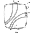
- FIG. 4 is a front elevation view of the enclosure of FIG. 1 , showing the outer cover in the closed position.
- an enclosure 10 is provided for housing communications equipment at a subscriber premises.
- the enclosure may be of the type commonly known as a Network Interface Device (NID), but could also comprise other types of enclosures, for example a Multi Welling Unit (MDU) enclosure, an Optical Network Terminal (ONT) enclosure, a Building Entrance Terminal (BET) enclosure or other subscriber termination housing. Therefore, it should be clear that the present invention is not limited to use of the enclosure as a NID.
- NID Network Interface Device
- MDU Multi Welling Unit
- ONT Optical Network Terminal
- BET Building Entrance Terminal
- Enclosure 10 receives at least one service provider cable 12, at least one subscriber cable 14, and at least one ground cable 16. It should further be understood that the present invention has utility with various types of cables and the resulting connections between the communications network belong to the service provider and the communications equipment belonging to the subscriber. Therefore, the present invention is not limited to any particular type or types of cables. Accordingly, as discussed below, service provider cable 12 may be a twisted wire pair cable, a coaxial cable, a composite (twisted wire pair and coaxial) cable, or a fiber optic cable. Also, service provider cable 12 could comprise more than one of the above types of cables, depending on the subscriber equipment, the type of installation, and the services available from the service provider or providers.
- subscriber cable 14 may be a twisted wire pair cable, a coaxial cable, a composite cable or a fiber optic cable. In many subscriber premises, multiple subscriber cables 14 could be employed for the desired connections, such as multiple telephone lines, data lines, video (e.g., cable television) lines, etc.
- One or more ground cables 16 may also be employed, if desired, connected to earth ground or to other grounding structure.
- Enclosure 10 and its various terminations may also be configured so as to be used with pre-connectorized cables, and in particular, one or more pre-connectorized fiber optic cables. Enclosure 10 may therefore be used with any possible combination of cables, and the present invention should not be limited by the specific examples depicted herein.
- Enclosure 10 includes a housing 18 having a base 20 and an outer cover 22 movably attached to the base.
- outer cover 22 is configured as a door with hinges 24 on the left side (as shown) of outer cover 22 and base 20.
- hinges 24 could be located along any other side if desired.
- other structure could be added or substituted, such as slides, snaps, screws, etc. for attaching outer cover 22 to base 20.
- Outer cover 22 is movable between an opened position (as shown in FIG. 1 ) and a closed position (as shown in FIG. 4 ).
- Outer cover 22 and base 20 define a housing interior volume 26 when the outer cover is in the closed position.
- active electronic components 40 are removably mounted in the housing interior volume 26.
- active electronic components 40 include a printed circuit board (PCB) 42, which may be connected via a component housing 44 to enclosure 10.
- PCB printed circuit board
- Component housing 44 may function as an inner cover, as will be described below.
- housing/inner cover 44 is connected to enclosure 10 via hinges 45 connected to base 20.
- other connecting structures and connection locations could be employed for housing/inner cover 44.
- Active electronic components 40 are typically owned by the service provider and provide some of the connection path between service provider cable 12 and subscriber cable 14. Active electronic components 40 could function to process and split multiple signals from service provider cable 12 into component parts (e.g., voice, data, and video) to be transmitted along different subscriber cables 14. Numerous variations are possible for the active electronic components 40, and no limitation on such components should be implied by the illustrations herein.
- grounding post 52 extends upwardly from base 22 within the housing interior volume 26.
- Ground cable 16 is electrically connectable with grounding post 52.
- one or more ground lugs 54 may be attached to grounding post 52 via a threaded nut 55 to connect ground cable 16 and/or other elements to the grounding post 52.
- An aperture 53 is provided though active electronic components 40 and located for receiving grounding post 52.
- ground cable 16 may be attached to grounding post 52 in other ways, such as by "j-hooking" the ground cable 16 to the grounding post 52 and/or directly securing the ground cable, for example with nut 55.
- ground lug 54 Use of the laterally extending ground lug 54 retained by nut 55 allows for a reduction in height along grounding post 52 and allows for a clear connection path between PCB 42 and the grounding post.
- other configurations are possible, depending on the configuration of PCB 42, housing/inner cover 44, ground cable 16 and grounding post 52.
- grounding post 52 extends through aperture 53 in PCB 42 and an electrically conductive ground connection portion 56 of PCB 42 contacts grounding post shoulder 58.
- Shoulder 58 is illustrated as a slot in post 52, but could be any other shape, or a portion of threaded nut 55, if so desired.
- a service provider security nut 60 is attachable to grounding post 52, for example by cooperative threads (see FIG. 3 ).
- active electronic components 40 are fixed within the interior volume 26 of the housing 18 and are grounded via grounding post 52 and the ground cable 16.
- housing/inner cover 44 provides secure protection for a service provider portion 62 of the housing interior volume 26, thereby providing a service provider compartment between the housing/inner cover 44 and base 20.
- subscriber connection equipment 64 may include one or more of twisted wire pair terminations (such as screw terminals 66 or RJ-type voice 68 or data 70 connections), coaxial terminations 72, and/or fiber optic terminations 74. Other termination types may be employed as well, such as biased spring terminals, etc. Multiple terminations of each type may be provided as desired so as to provide a flexible enclosure 10 useful in different applications. Also, other optional items (not shown) such as splitters, splice kits, pigtails, etc. may be provided by the subscriber to meet the individual needs of the subscriber premises.
- a conventional subscriber bridge or line module could be included. If so, the various subscriber terminations could be located on a portion of the subscriber bridge available to the subscriber when the housing/inner cover 44 is closed, and additional jacks could be provided in the subscriber bridge as a point of demarcation between a service provider line and a subscriber line for testing connections directly to the service provider equipment. Such jacks and terminations are essentially incorporated into housing/inner cover 44 in the embodiment of FIGS. 1-4 . Also, other termination types could be employed, such as insulation displacement connectors (IDC connectors), if desired.
- IDC connectors insulation displacement connectors
- enclosure 10 may incorporate a skirt 76 extending in a first direction 78 along a lower edge of outer cover 22.
- Skirt 76 is provided to allow for a more aesthetic, continuous edge of enclosure 10. Therefore, substantially continuous edge 80 of skirt 76 extends in the first direction 78 at least as far as cable ports 34 and bottom mounting foot 36. By covering cable ports 34 and mounting foot 36 , these elements are more protected from unintentional or unwanted contact, and improve the aesthetics of the outer cover 22 and enclosure 10 in general.
- hinges 24 are arranged so as to be not visible from the front side of enclosure 10, and an opening 82 for a subscriber padlock is also located within the substantially continuous perimeter of outer cover 22, thereby providing a further continuous and aesthetically pleasing housing 18.
Landscapes
- Engineering & Computer Science (AREA)
- Physics & Mathematics (AREA)
- Computer Networks & Wireless Communication (AREA)
- General Physics & Mathematics (AREA)
- Optics & Photonics (AREA)
- Signal Processing (AREA)
- Health & Medical Sciences (AREA)
- Toxicology (AREA)
- Computer Security & Cryptography (AREA)
- Microelectronics & Electronic Packaging (AREA)
- Structure Of Telephone Exchanges (AREA)
- Two-Way Televisions, Distribution Of Moving Picture Or The Like (AREA)
Claims (8)
- Enceinte (10) destinée au logement d'un matériel de communications dans les locaux d'un abonné, cette enceinte (10) recevant au moins un câble de fournisseur de services (12), au moins un câble d'abonné (14), et au moins un câble de terre (16), cette enceinte (10) comprenant un logement (18) ayant une base (20) et un couvercle extérieur (22) attaché de manière amovible à la base (20), ce couvercle extérieur (22) pouvant être bougé entre une position ouverte et une position fermée, le couvercle extérieur (22) et la base (20) définissant un volume intérieur de logement (26) lorsque le couvercle extérieur (22) est dans la position fermée ; la base (20) définissant au moins un orifice pour câble pour recevoir le câble du fournisseur de services, le câble de l'abonné et le câble de terre ; une borne de mise à la terre (52) s'étendant depuis la base (20) à l'intérieur du volume intérieur du logement (26), le câble de terre étant connectable électriquement avec la borne de mise à la terre (52) ; des composants électroniques actifs (40) situés à l'intérieur du volume intérieur du logement (26), ces composants électroniques actifs (40) connectant le câble du fournisseur de services avec le câble de l'abonné ; et des moyens à la fois pour fixer les composants électroniques actifs (40) à l'intérieur du logement (18) et pour mettre à la terre les composants électroniques actifs (40) en les connectant à la borne de mise à la terre (52) et au câble de terre, une cosse de mise à la terre (54) attachée à la borne de mise à la terre (52), le câble de terre pouvant être attaché à la cosse de mise à la terre (54), caractérisée en ce que l'enceinte (10) comprend en outre un couvercle intérieur (44) attaché de manière amovible à la base (20) via une charnière et pouvant être bougé entre une position ouverte et une position fermée, les composants électroniques actifs (40) étant montés sur ce couvercle intérieur (44).
- Enceinte selon la revendication 1, caractérisée en ce qu'un écrou de sécurité du fournisseur de services (60) fixe le couvercle intérieur (44) dans la position fermée lors de la fixation et de la mise à la terre des composants électroniques actifs (40).
- Enceinte selon la revendication 2, caractérisée en ce que le matériel du fournisseur de services et le matériel de connexion de l'abonné (64) sont situés à l'intérieur du volume intérieur du logement (26), et dans lequel, lorsque le couvercle extérieur (22) est dans la position ouverte et que le couvercle intérieur (44) est dans la position fermée avec l'écrou de sécurité du fournisseur de services (60) attaché à la borne de mise à la terre (52), l'accès au matériel du fournisseur de services est essentiellement empêché, alors que l'accès au matériel de connexion de l'abonné est permis.
- Enceinte selon la revendication 3, caractérisée en ce que, lorsque le couvercle extérieur (22) et le couvercle intérieur (44) sont dans la position ouverte, l'accès au matériel du fournisseur de services est permis.
- Enceinte selon la revendication 1, caractérisée en ce que les composants électroniques actifs (40) comprennent une carte de circuits imprimés (PCB).
- Enceinte selon la revendication 5, caractérisée en ce que la borne de mise à la terre (52) s'étend à travers la carte de circuits imprimés (PCB) et est en contact électrique avec celle-ci lorsque les composants électroniques (40) sont fixés et mis à la terre.
- Enceinte selon la revendication 1, caractérisée en ce que la base (20) comprend une paroi arrière (28) et une paroi périmétrique (30) s'étendant vers l'extérieur depuis la paroi arrière, cette paroi périmétrique comprenant une paroi d'extrémité (32) qui définit l'au moins un orifice pour câble (34) s'étendant depuis celle-ci dans une première direction, le couvercle extérieur (22) ayant une jupe (76) définissant un bord essentiellement continu (80), cette jupe (76) s'étendant dans la première direction au-delà de la paroi d'extrémité (32) au moins aussi loin que l'au moins un orifice pour câble lorsque le couvercle extérieur est dans la position fermée.
- Enceinte selon la revendication 1, caractérisée en ce que le couvercle intérieur et la base définissent un compartiment de fournisseur de services (62) à l'intérieur du volume intérieur du logement (26) lorsque le couvercle intérieur (44) est dans la position fermée ; en ce que la borne de mise à la terre (52) s'étend depuis la base (20) à l'intérieur du compartiment du fournisseur de services (62) ; en ce que les composants électroniques actifs (40) sont positionnés à l'intérieur du compartiment du fournisseur de services (62) ; en ce que le couvercle intérieur (44) est fixé dans la position fermée à la borne de mise à la terre (52) pour empêcher l'accès au compartiment du fournisseur de services (62) et pour mettre à la terre les composants électroniques actifs (40) en les connectant à la borne de mise à la terre (52) et au câble de terre ; et en ce que le couvercle intérieur (44) et les composants électroniques actifs (40) peuvent être enlevés du logement (18) lorsque la couvercle intérieur (44) est dans la position ouverte.
Applications Claiming Priority (2)
| Application Number | Priority Date | Filing Date | Title |
|---|---|---|---|
| US11/439,088 US7619160B2 (en) | 2006-05-23 | 2006-05-23 | Enclosure for housing communications equipment |
| PCT/US2007/012281 WO2007139822A2 (fr) | 2006-05-23 | 2007-05-23 | Enceinte destinée au logement d'un matériel de communication |
Publications (2)
| Publication Number | Publication Date |
|---|---|
| EP2020166A2 EP2020166A2 (fr) | 2009-02-04 |
| EP2020166B1 true EP2020166B1 (fr) | 2011-10-12 |
Family
ID=38748478
Family Applications (1)
| Application Number | Title | Priority Date | Filing Date |
|---|---|---|---|
| EP07809156A Not-in-force EP2020166B1 (fr) | 2006-05-23 | 2007-05-23 | Enceinte destinée au logement d'un matériel de communication |
Country Status (6)
| Country | Link |
|---|---|
| US (1) | US7619160B2 (fr) |
| EP (1) | EP2020166B1 (fr) |
| AT (1) | ATE528977T1 (fr) |
| AU (1) | AU2007267992B2 (fr) |
| CA (1) | CA2652817C (fr) |
| WO (1) | WO2007139822A2 (fr) |
Families Citing this family (38)
| Publication number | Priority date | Publication date | Assignee | Title |
|---|---|---|---|---|
| US7816602B2 (en) | 2006-02-13 | 2010-10-19 | Adc Telecommunications, Inc. | Fiber distribution hub with outside accessible grounding terminals |
| US20090114413A1 (en) * | 2007-11-07 | 2009-05-07 | Daviau William A | Insulated Housing |
| US8887220B2 (en) | 2008-07-25 | 2014-11-11 | At&T Intellectual Property I, L.P. | Network interface devices |
| US8279805B2 (en) | 2009-08-24 | 2012-10-02 | At&T Intellectual Property I, L.P. | Residential gateway |
| US8687506B2 (en) * | 2009-12-14 | 2014-04-01 | At&T Intellectual Property I, L.P. | Identifying network performance alert conditions |
| US9042237B2 (en) | 2009-12-14 | 2015-05-26 | At&T Intellectual Property I, L.P. | Identifying network performance alert conditions |
| EP2710743B1 (fr) | 2011-05-17 | 2018-08-29 | Corning Research & Development Corporation | Réseau intra-bâtiment convergent |
| US9106981B2 (en) | 2011-10-03 | 2015-08-11 | Tyco Electronics Uk Ltd | Aggregation enclosure for elevated, outdoor locations |
| US9370117B2 (en) * | 2013-08-14 | 2016-06-14 | Wirepath Home Systems, Llc | Recessed equipment boxes and related assemblies and methods |
| US10270236B2 (en) | 2013-08-14 | 2019-04-23 | Wirepath Home Systems, Llc | Recessed equipment boxes and related assemblies and methods |
| US9716924B2 (en) * | 2013-10-21 | 2017-07-25 | Centurylink Intellectual Property Llc | Omedia panel |
| EP3149520B1 (fr) | 2014-05-27 | 2021-09-01 | Corning Research & Development Corporation | Ensembles et plateaux de gestion de fibres et dispositifs d'interface réseau intégrant lesdits ensembles et plateaux |
| US10509187B2 (en) * | 2014-09-23 | 2019-12-17 | Ppc Broadband, Inc. | Universal multi-purpose compartmentalized telecommunications box |
| US10976512B2 (en) * | 2014-09-23 | 2021-04-13 | Ppc Broadband, Inc. | House box with mounting surface for mounted access |
| WO2016049242A1 (fr) | 2014-09-23 | 2016-03-31 | Ppc Broadband, Inc. | Boîtier de télécommunications compartimenté multifonction universel |
| US9882362B2 (en) * | 2014-09-23 | 2018-01-30 | Ppc Broadband, Inc. | Enclosure for controling access to different telecommunication components |
| US9952396B2 (en) * | 2014-09-30 | 2018-04-24 | CommScope Connectivity Belgium BVBA | System and method of fiber distribution |
| US10021807B2 (en) | 2015-03-31 | 2018-07-10 | Wirepath Home Systems, Llc | Media enclosures and related assemblies and systems |
| JP1545404S (fr) * | 2015-05-19 | 2016-03-14 | ||
| WO2016191094A1 (fr) * | 2015-05-27 | 2016-12-01 | 3M Innovative Properties Company | Ensembles de gestion de fibres et dispositifs d'interface réseau intégrant de tels ensembles |
| USD813187S1 (en) * | 2016-04-29 | 2018-03-20 | Corning Optical Communications LLC | Telecommunication terminal cabinet |
| US20180031788A1 (en) * | 2016-07-29 | 2018-02-01 | Corning Optical Communications LLC | Sealed fiber optic/electrical distribution device |
| USD835040S1 (en) | 2016-09-09 | 2018-12-04 | Corning Research & Development Corporation | 1×4 distribution point unit |
| JP6809419B2 (ja) * | 2017-09-08 | 2021-01-06 | 三菱電機株式会社 | 電流電圧計測装置 |
| US10230226B1 (en) | 2018-07-03 | 2019-03-12 | Afl Telecommunications Llc | Network interface devices |
| US11239668B2 (en) * | 2018-09-21 | 2022-02-01 | Google Llc | Charger case for wearable electronics |
| US11061196B2 (en) | 2018-10-16 | 2021-07-13 | CommScope Connectivity Belgium BVBA | Enclosure with restricted access region |
| WO2020150392A1 (fr) * | 2019-01-15 | 2020-07-23 | Commscope Technologies Llc | Système de charnière de plateau |
| DE102019106679B4 (de) * | 2019-03-15 | 2021-01-07 | Ewe Tel Gmbh | Verfahren zum Anschließen eines Gebäudes an ein Glasfasernetz und Anschluss eines Gebäudes an ein Glasfasernetz |
| US12210203B2 (en) | 2019-03-29 | 2025-01-28 | Commscope Technologies Llc | Tray hinge interface system with opposing recessed surfaces recessed toward the pivot axis |
| US11726284B2 (en) * | 2019-04-12 | 2023-08-15 | Commscope Technologies Llc | Extender system for telecommunications enclosures |
| BR102019014363A2 (pt) * | 2019-07-11 | 2021-01-19 | Furukawa Electric Latam S.A. | caixa de terminação e derivação óptica |
| CN110568572B (zh) * | 2019-07-29 | 2021-08-31 | 华为技术有限公司 | 一种终端盒 |
| US11456566B2 (en) * | 2020-03-05 | 2022-09-27 | Applied Optoelectronics, Inc. | Coaxial connector seizure assembly with integrated mechanical stop and a hybrid fiber-coaxial (HFC) module implementing same |
| US11445633B2 (en) * | 2021-01-14 | 2022-09-13 | Super Micro Computer, Inc. | Telecommunication cabinet with hidden anti-theft heat dissipation module |
| FR3138705A1 (fr) * | 2022-08-05 | 2024-02-09 | Telenco Networks | Boîtier de raccordement pour câbles de télécommunication |
| KR102802686B1 (ko) * | 2022-10-14 | 2025-05-07 | 탈렌티스 주식회사 | 광동 복합 단자함 |
| EP4670550A1 (fr) | 2024-06-24 | 2025-12-31 | Premec S.P.A. | Dispositif de fermeture pour chaussures de sport |
Family Cites Families (9)
| Publication number | Priority date | Publication date | Assignee | Title |
|---|---|---|---|---|
| US4742541A (en) | 1983-10-25 | 1988-05-03 | Northern Telecom Limited | Telecommunications interface with protector modules |
| US4850014A (en) * | 1987-03-10 | 1989-07-18 | Communications Systems, Inc. | Multiple dwelling interface box |
| US4917615A (en) * | 1988-11-18 | 1990-04-17 | Franks George J Jr | Ground bracket |
| US4882647A (en) * | 1988-12-15 | 1989-11-21 | Keptel, Inc. | Combination apparatus for clamping ground conductor and for mounting lightning protector |
| US6652295B1 (en) | 1997-02-28 | 2003-11-25 | Maris Anthony Glass | Ground bus for junction box |
| US6795552B1 (en) | 1999-12-14 | 2004-09-21 | Corning Cable Systems Llc | Enhanced services network interface device |
| US6535579B1 (en) | 2000-05-31 | 2003-03-18 | Corning Cable Systems Llc | Network interface device with disconnectable half-ringer |
| US6815612B2 (en) | 2002-10-18 | 2004-11-09 | Corning Cable Systems Llc | Watertight seal for network interface device |
| US20060153362A1 (en) | 2005-01-13 | 2006-07-13 | Bloodworth Stephen G | Network interface device for fiber optic communications network |
-
2006
- 2006-05-23 US US11/439,088 patent/US7619160B2/en active Active
-
2007
- 2007-05-23 AT AT07809156T patent/ATE528977T1/de not_active IP Right Cessation
- 2007-05-23 WO PCT/US2007/012281 patent/WO2007139822A2/fr not_active Ceased
- 2007-05-23 AU AU2007267992A patent/AU2007267992B2/en not_active Ceased
- 2007-05-23 EP EP07809156A patent/EP2020166B1/fr not_active Not-in-force
- 2007-05-23 CA CA2652817A patent/CA2652817C/fr active Active
Also Published As
| Publication number | Publication date |
|---|---|
| AU2007267992B2 (en) | 2011-07-28 |
| US20070272440A1 (en) | 2007-11-29 |
| AU2007267992A1 (en) | 2007-12-06 |
| CA2652817A1 (fr) | 2007-12-06 |
| EP2020166A2 (fr) | 2009-02-04 |
| US7619160B2 (en) | 2009-11-17 |
| WO2007139822A2 (fr) | 2007-12-06 |
| ATE528977T1 (de) | 2011-10-15 |
| CA2652817C (fr) | 2017-02-14 |
| WO2007139822A3 (fr) | 2008-08-28 |
Similar Documents
| Publication | Publication Date | Title |
|---|---|---|
| CA2652817C (fr) | Enceinte destinee au logement d'un materiel de communication | |
| US6137866A (en) | Indoor XDSL splitter assembly | |
| US8139761B2 (en) | Network interface device, apparatus, and methods | |
| US6815612B2 (en) | Watertight seal for network interface device | |
| US4949376A (en) | Telephone network interface apparatus | |
| US6795552B1 (en) | Enhanced services network interface device | |
| US20060153516A1 (en) | Network interface device having integral slack storage compartment | |
| CA2676110C (fr) | Assemblage de couverture multipiece et assemblage de dispositif modulaire | |
| CA2962267A1 (fr) | Boitier de telecommunications compartimente multifonction universel | |
| US5803292A (en) | Uniform building entrance protector housing construction with expandable splice chamber | |
| US8247708B1 (en) | Cable seal apparatus and techniques for outside plant telecommunications housings | |
| US20070160193A1 (en) | Network interface device, apparatus, and methods | |
| JPH04264377A (ja) | 建物予配線用の低電流コンセント | |
| US20070160194A1 (en) | Network interface device, apparatus, and methods | |
| US6157714A (en) | Modular layered network interface unit particularly suited to a two-layer arrangement | |
| US10187515B2 (en) | Network interface devices having external demarcation points | |
| US20070147602A1 (en) | Network interface device, apparatus, and methods | |
| US7499526B2 (en) | Termination module including subscriber bridge having burglar alarm connections | |
| US6320125B1 (en) | Electronics enclosure |
Legal Events
| Date | Code | Title | Description |
|---|---|---|---|
| PUAI | Public reference made under article 153(3) epc to a published international application that has entered the european phase |
Free format text: ORIGINAL CODE: 0009012 |
|
| 17P | Request for examination filed |
Effective date: 20081121 |
|
| AK | Designated contracting states |
Kind code of ref document: A2 Designated state(s): AT BE BG CH CY CZ DE DK EE ES FI FR GB GR HU IE IS IT LI LT LU LV MC MT NL PL PT RO SE SI SK TR |
|
| AX | Request for extension of the european patent |
Extension state: AL BA HR MK RS |
|
| RIN1 | Information on inventor provided before grant (corrected) |
Inventor name: KEENUM, JOHN A. Inventor name: GRUNWALD, BRAD N. |
|
| RIN1 | Information on inventor provided before grant (corrected) |
Inventor name: GRUNWALD, BRAD N. Inventor name: KEENUM, JOHN A. |
|
| DAX | Request for extension of the european patent (deleted) | ||
| 17Q | First examination report despatched |
Effective date: 20100507 |
|
| RIN1 | Information on inventor provided before grant (corrected) |
Inventor name: KEENUM, JOHN A. Inventor name: GRUNWALD, BRAD N. |
|
| GRAP | Despatch of communication of intention to grant a patent |
Free format text: ORIGINAL CODE: EPIDOSNIGR1 |
|
| RIN1 | Information on inventor provided before grant (corrected) |
Inventor name: KEENUM, JOHN A. Inventor name: GRUNWALD, BRAD N. |
|
| GRAS | Grant fee paid |
Free format text: ORIGINAL CODE: EPIDOSNIGR3 |
|
| GRAA | (expected) grant |
Free format text: ORIGINAL CODE: 0009210 |
|
| RAP1 | Party data changed (applicant data changed or rights of an application transferred) |
Owner name: CORNING CABLE SYSTEMS LLC |
|
| AK | Designated contracting states |
Kind code of ref document: B1 Designated state(s): AT BE BG CH CY CZ DE DK EE ES FI FR GB GR HU IE IS IT LI LT LU LV MC MT NL PL PT RO SE SI SK TR |
|
| REG | Reference to a national code |
Ref country code: GB Ref legal event code: FG4D |
|
| REG | Reference to a national code |
Ref country code: CH Ref legal event code: EP |
|
| REG | Reference to a national code |
Ref country code: IE Ref legal event code: FG4D |
|
| REG | Reference to a national code |
Ref country code: DE Ref legal event code: R096 Ref document number: 602007017851 Country of ref document: DE Effective date: 20120112 |
|
| REG | Reference to a national code |
Ref country code: NL Ref legal event code: VDEP Effective date: 20111012 |
|
| LTIE | Lt: invalidation of european patent or patent extension |
Effective date: 20111012 |
|
| REG | Reference to a national code |
Ref country code: AT Ref legal event code: MK05 Ref document number: 528977 Country of ref document: AT Kind code of ref document: T Effective date: 20111012 |
|
| PG25 | Lapsed in a contracting state [announced via postgrant information from national office to epo] |
Ref country code: BE Free format text: LAPSE BECAUSE OF FAILURE TO SUBMIT A TRANSLATION OF THE DESCRIPTION OR TO PAY THE FEE WITHIN THE PRESCRIBED TIME-LIMIT Effective date: 20111012 Ref country code: IS Free format text: LAPSE BECAUSE OF FAILURE TO SUBMIT A TRANSLATION OF THE DESCRIPTION OR TO PAY THE FEE WITHIN THE PRESCRIBED TIME-LIMIT Effective date: 20120212 Ref country code: LT Free format text: LAPSE BECAUSE OF FAILURE TO SUBMIT A TRANSLATION OF THE DESCRIPTION OR TO PAY THE FEE WITHIN THE PRESCRIBED TIME-LIMIT Effective date: 20111012 |
|
| PG25 | Lapsed in a contracting state [announced via postgrant information from national office to epo] |
Ref country code: PT Free format text: LAPSE BECAUSE OF FAILURE TO SUBMIT A TRANSLATION OF THE DESCRIPTION OR TO PAY THE FEE WITHIN THE PRESCRIBED TIME-LIMIT Effective date: 20120213 Ref country code: SI Free format text: LAPSE BECAUSE OF FAILURE TO SUBMIT A TRANSLATION OF THE DESCRIPTION OR TO PAY THE FEE WITHIN THE PRESCRIBED TIME-LIMIT Effective date: 20111012 Ref country code: SE Free format text: LAPSE BECAUSE OF FAILURE TO SUBMIT A TRANSLATION OF THE DESCRIPTION OR TO PAY THE FEE WITHIN THE PRESCRIBED TIME-LIMIT Effective date: 20111012 Ref country code: GR Free format text: LAPSE BECAUSE OF FAILURE TO SUBMIT A TRANSLATION OF THE DESCRIPTION OR TO PAY THE FEE WITHIN THE PRESCRIBED TIME-LIMIT Effective date: 20120113 Ref country code: LV Free format text: LAPSE BECAUSE OF FAILURE TO SUBMIT A TRANSLATION OF THE DESCRIPTION OR TO PAY THE FEE WITHIN THE PRESCRIBED TIME-LIMIT Effective date: 20111012 Ref country code: NL Free format text: LAPSE BECAUSE OF FAILURE TO SUBMIT A TRANSLATION OF THE DESCRIPTION OR TO PAY THE FEE WITHIN THE PRESCRIBED TIME-LIMIT Effective date: 20111012 |
|
| PG25 | Lapsed in a contracting state [announced via postgrant information from national office to epo] |
Ref country code: CY Free format text: LAPSE BECAUSE OF FAILURE TO SUBMIT A TRANSLATION OF THE DESCRIPTION OR TO PAY THE FEE WITHIN THE PRESCRIBED TIME-LIMIT Effective date: 20111012 |
|
| PG25 | Lapsed in a contracting state [announced via postgrant information from national office to epo] |
Ref country code: DK Free format text: LAPSE BECAUSE OF FAILURE TO SUBMIT A TRANSLATION OF THE DESCRIPTION OR TO PAY THE FEE WITHIN THE PRESCRIBED TIME-LIMIT Effective date: 20111012 Ref country code: CZ Free format text: LAPSE BECAUSE OF FAILURE TO SUBMIT A TRANSLATION OF THE DESCRIPTION OR TO PAY THE FEE WITHIN THE PRESCRIBED TIME-LIMIT Effective date: 20111012 Ref country code: EE Free format text: LAPSE BECAUSE OF FAILURE TO SUBMIT A TRANSLATION OF THE DESCRIPTION OR TO PAY THE FEE WITHIN THE PRESCRIBED TIME-LIMIT Effective date: 20111012 Ref country code: SK Free format text: LAPSE BECAUSE OF FAILURE TO SUBMIT A TRANSLATION OF THE DESCRIPTION OR TO PAY THE FEE WITHIN THE PRESCRIBED TIME-LIMIT Effective date: 20111012 Ref country code: BG Free format text: LAPSE BECAUSE OF FAILURE TO SUBMIT A TRANSLATION OF THE DESCRIPTION OR TO PAY THE FEE WITHIN THE PRESCRIBED TIME-LIMIT Effective date: 20120112 |
|
| PLBE | No opposition filed within time limit |
Free format text: ORIGINAL CODE: 0009261 |
|
| STAA | Information on the status of an ep patent application or granted ep patent |
Free format text: STATUS: NO OPPOSITION FILED WITHIN TIME LIMIT |
|
| PG25 | Lapsed in a contracting state [announced via postgrant information from national office to epo] |
Ref country code: IT Free format text: LAPSE BECAUSE OF FAILURE TO SUBMIT A TRANSLATION OF THE DESCRIPTION OR TO PAY THE FEE WITHIN THE PRESCRIBED TIME-LIMIT Effective date: 20111012 Ref country code: RO Free format text: LAPSE BECAUSE OF FAILURE TO SUBMIT A TRANSLATION OF THE DESCRIPTION OR TO PAY THE FEE WITHIN THE PRESCRIBED TIME-LIMIT Effective date: 20111012 Ref country code: PL Free format text: LAPSE BECAUSE OF FAILURE TO SUBMIT A TRANSLATION OF THE DESCRIPTION OR TO PAY THE FEE WITHIN THE PRESCRIBED TIME-LIMIT Effective date: 20111012 |
|
| 26N | No opposition filed |
Effective date: 20120713 |
|
| REG | Reference to a national code |
Ref country code: DE Ref legal event code: R097 Ref document number: 602007017851 Country of ref document: DE Effective date: 20120713 |
|
| PG25 | Lapsed in a contracting state [announced via postgrant information from national office to epo] |
Ref country code: MC Free format text: LAPSE BECAUSE OF NON-PAYMENT OF DUE FEES Effective date: 20120531 |
|
| REG | Reference to a national code |
Ref country code: CH Ref legal event code: PL |
|
| PG25 | Lapsed in a contracting state [announced via postgrant information from national office to epo] |
Ref country code: LI Free format text: LAPSE BECAUSE OF NON-PAYMENT OF DUE FEES Effective date: 20120531 Ref country code: AT Free format text: LAPSE BECAUSE OF FAILURE TO SUBMIT A TRANSLATION OF THE DESCRIPTION OR TO PAY THE FEE WITHIN THE PRESCRIBED TIME-LIMIT Effective date: 20111012 Ref country code: CH Free format text: LAPSE BECAUSE OF NON-PAYMENT OF DUE FEES Effective date: 20120531 |
|
| REG | Reference to a national code |
Ref country code: IE Ref legal event code: MM4A |
|
| PG25 | Lapsed in a contracting state [announced via postgrant information from national office to epo] |
Ref country code: IE Free format text: LAPSE BECAUSE OF NON-PAYMENT OF DUE FEES Effective date: 20120523 Ref country code: ES Free format text: LAPSE BECAUSE OF FAILURE TO SUBMIT A TRANSLATION OF THE DESCRIPTION OR TO PAY THE FEE WITHIN THE PRESCRIBED TIME-LIMIT Effective date: 20120123 |
|
| PG25 | Lapsed in a contracting state [announced via postgrant information from national office to epo] |
Ref country code: FI Free format text: LAPSE BECAUSE OF FAILURE TO SUBMIT A TRANSLATION OF THE DESCRIPTION OR TO PAY THE FEE WITHIN THE PRESCRIBED TIME-LIMIT Effective date: 20111012 |
|
| PG25 | Lapsed in a contracting state [announced via postgrant information from national office to epo] |
Ref country code: MT Free format text: LAPSE BECAUSE OF FAILURE TO SUBMIT A TRANSLATION OF THE DESCRIPTION OR TO PAY THE FEE WITHIN THE PRESCRIBED TIME-LIMIT Effective date: 20111012 |
|
| PG25 | Lapsed in a contracting state [announced via postgrant information from national office to epo] |
Ref country code: TR Free format text: LAPSE BECAUSE OF FAILURE TO SUBMIT A TRANSLATION OF THE DESCRIPTION OR TO PAY THE FEE WITHIN THE PRESCRIBED TIME-LIMIT Effective date: 20111012 |
|
| PG25 | Lapsed in a contracting state [announced via postgrant information from national office to epo] |
Ref country code: LU Free format text: LAPSE BECAUSE OF NON-PAYMENT OF DUE FEES Effective date: 20120523 |
|
| PG25 | Lapsed in a contracting state [announced via postgrant information from national office to epo] |
Ref country code: HU Free format text: LAPSE BECAUSE OF FAILURE TO SUBMIT A TRANSLATION OF THE DESCRIPTION OR TO PAY THE FEE WITHIN THE PRESCRIBED TIME-LIMIT Effective date: 20070523 |
|
| REG | Reference to a national code |
Ref country code: FR Ref legal event code: PLFP Year of fee payment: 10 |
|
| REG | Reference to a national code |
Ref country code: FR Ref legal event code: PLFP Year of fee payment: 11 |
|
| REG | Reference to a national code |
Ref country code: FR Ref legal event code: PLFP Year of fee payment: 12 |
|
| REG | Reference to a national code |
Ref country code: FR Ref legal event code: PLFP Year of fee payment: 17 |
|
| PGFP | Annual fee paid to national office [announced via postgrant information from national office to epo] |
Ref country code: FR Payment date: 20230412 Year of fee payment: 17 Ref country code: DE Payment date: 20230412 Year of fee payment: 17 |
|
| PGFP | Annual fee paid to national office [announced via postgrant information from national office to epo] |
Ref country code: GB Payment date: 20230412 Year of fee payment: 17 |
|
| REG | Reference to a national code |
Ref country code: DE Ref legal event code: R119 Ref document number: 602007017851 Country of ref document: DE |
|
| GBPC | Gb: european patent ceased through non-payment of renewal fee |
Effective date: 20240523 |
|
| PG25 | Lapsed in a contracting state [announced via postgrant information from national office to epo] |
Ref country code: DE Free format text: LAPSE BECAUSE OF NON-PAYMENT OF DUE FEES Effective date: 20241203 |
|
| PG25 | Lapsed in a contracting state [announced via postgrant information from national office to epo] |
Ref country code: FR Free format text: LAPSE BECAUSE OF NON-PAYMENT OF DUE FEES Effective date: 20240531 |
|
| PG25 | Lapsed in a contracting state [announced via postgrant information from national office to epo] |
Ref country code: GB Free format text: LAPSE BECAUSE OF NON-PAYMENT OF DUE FEES Effective date: 20240523 |