EP2020261A1 - System zur Erzeugung von Teilchen mit mehreren Komponenten - Google Patents
System zur Erzeugung von Teilchen mit mehreren Komponenten Download PDFInfo
- Publication number
- EP2020261A1 EP2020261A1 EP07112887A EP07112887A EP2020261A1 EP 2020261 A1 EP2020261 A1 EP 2020261A1 EP 07112887 A EP07112887 A EP 07112887A EP 07112887 A EP07112887 A EP 07112887A EP 2020261 A1 EP2020261 A1 EP 2020261A1
- Authority
- EP
- European Patent Office
- Prior art keywords
- particle
- fluid jet
- nozzle
- multicomponent
- isolated
- Prior art date
- Legal status (The legal status is an assumption and is not a legal conclusion. Google has not performed a legal analysis and makes no representation as to the accuracy of the status listed.)
- Withdrawn
Links
- 239000002245 particle Substances 0.000 title claims abstract description 99
- 239000012530 fluid Substances 0.000 claims abstract description 84
- 238000000034 method Methods 0.000 claims abstract description 37
- 239000000463 material Substances 0.000 claims description 62
- 238000005538 encapsulation Methods 0.000 claims description 14
- 239000007787 solid Substances 0.000 claims description 10
- 238000000576 coating method Methods 0.000 claims description 9
- 239000007788 liquid Substances 0.000 claims description 9
- 239000011248 coating agent Substances 0.000 claims description 6
- 239000011159 matrix material Substances 0.000 claims description 5
- 239000000126 substance Substances 0.000 claims description 5
- 230000035699 permeability Effects 0.000 claims description 4
- 239000000758 substrate Substances 0.000 claims description 4
- 239000000376 reactant Substances 0.000 claims description 3
- 230000001960 triggered effect Effects 0.000 claims description 3
- 230000001681 protective effect Effects 0.000 claims description 2
- 239000012798 spherical particle Substances 0.000 claims description 2
- 230000003111 delayed effect Effects 0.000 claims 1
- LFQSCWFLJHTTHZ-UHFFFAOYSA-N Ethanol Chemical compound CCO LFQSCWFLJHTTHZ-UHFFFAOYSA-N 0.000 description 20
- XLYOFNOQVPJJNP-UHFFFAOYSA-N water Substances O XLYOFNOQVPJJNP-UHFFFAOYSA-N 0.000 description 15
- 239000000839 emulsion Substances 0.000 description 11
- 239000004615 ingredient Substances 0.000 description 8
- 230000000694 effects Effects 0.000 description 6
- 235000013305 food Nutrition 0.000 description 6
- 238000010438 heat treatment Methods 0.000 description 6
- 239000002537 cosmetic Substances 0.000 description 5
- 239000012071 phase Substances 0.000 description 5
- 239000011257 shell material Substances 0.000 description 5
- 229910000679 solder Inorganic materials 0.000 description 5
- 230000008901 benefit Effects 0.000 description 4
- 150000001875 compounds Chemical class 0.000 description 4
- 239000011162 core material Substances 0.000 description 4
- 239000007789 gas Substances 0.000 description 4
- 210000001035 gastrointestinal tract Anatomy 0.000 description 4
- 238000002156 mixing Methods 0.000 description 4
- 239000000203 mixture Substances 0.000 description 4
- 238000002203 pretreatment Methods 0.000 description 4
- 230000008569 process Effects 0.000 description 4
- 102000004190 Enzymes Human genes 0.000 description 3
- 108090000790 Enzymes Proteins 0.000 description 3
- 238000006243 chemical reaction Methods 0.000 description 3
- 238000001816 cooling Methods 0.000 description 3
- 238000001035 drying Methods 0.000 description 3
- 239000003292 glue Substances 0.000 description 3
- 239000003973 paint Substances 0.000 description 3
- LYCAIKOWRPUZTN-UHFFFAOYSA-N Ethylene glycol Chemical compound OCCO LYCAIKOWRPUZTN-UHFFFAOYSA-N 0.000 description 2
- QVGXLLKOCUKJST-UHFFFAOYSA-N atomic oxygen Chemical compound [O] QVGXLLKOCUKJST-UHFFFAOYSA-N 0.000 description 2
- 230000015572 biosynthetic process Effects 0.000 description 2
- 230000015556 catabolic process Effects 0.000 description 2
- 239000003054 catalyst Substances 0.000 description 2
- 238000002425 crystallisation Methods 0.000 description 2
- 230000008025 crystallization Effects 0.000 description 2
- 238000006731 degradation reaction Methods 0.000 description 2
- 238000009792 diffusion process Methods 0.000 description 2
- 238000011010 flushing procedure Methods 0.000 description 2
- 230000004907 flux Effects 0.000 description 2
- 150000002500 ions Chemical class 0.000 description 2
- 238000004519 manufacturing process Methods 0.000 description 2
- 239000002086 nanomaterial Substances 0.000 description 2
- 239000001301 oxygen Substances 0.000 description 2
- 229910052760 oxygen Inorganic materials 0.000 description 2
- 238000001556 precipitation Methods 0.000 description 2
- 230000005855 radiation Effects 0.000 description 2
- 230000001105 regulatory effect Effects 0.000 description 2
- 230000021317 sensory perception Effects 0.000 description 2
- 239000003381 stabilizer Substances 0.000 description 2
- 238000011144 upstream manufacturing Methods 0.000 description 2
- NOOLISFMXDJSKH-UTLUCORTSA-N (+)-Neomenthol Chemical compound CC(C)[C@@H]1CC[C@@H](C)C[C@@H]1O NOOLISFMXDJSKH-UTLUCORTSA-N 0.000 description 1
- NOOLISFMXDJSKH-UHFFFAOYSA-N DL-menthol Natural products CC(C)C1CCC(C)CC1O NOOLISFMXDJSKH-UHFFFAOYSA-N 0.000 description 1
- 241000196324 Embryophyta Species 0.000 description 1
- 240000002853 Nelumbo nucifera Species 0.000 description 1
- 235000006508 Nelumbo nucifera Nutrition 0.000 description 1
- 235000006510 Nelumbo pentapetala Nutrition 0.000 description 1
- 241000700605 Viruses Species 0.000 description 1
- 230000009471 action Effects 0.000 description 1
- 239000004480 active ingredient Substances 0.000 description 1
- 239000000654 additive Substances 0.000 description 1
- 238000004026 adhesive bonding Methods 0.000 description 1
- 229940072056 alginate Drugs 0.000 description 1
- 229920000615 alginic acid Polymers 0.000 description 1
- 230000000844 anti-bacterial effect Effects 0.000 description 1
- 230000003373 anti-fouling effect Effects 0.000 description 1
- 230000000843 anti-fungal effect Effects 0.000 description 1
- 229940121375 antifungal agent Drugs 0.000 description 1
- 239000003963 antioxidant agent Substances 0.000 description 1
- 239000012620 biological material Substances 0.000 description 1
- 230000008859 change Effects 0.000 description 1
- 238000004581 coalescence Methods 0.000 description 1
- 239000003086 colorant Substances 0.000 description 1
- 238000004040 coloring Methods 0.000 description 1
- 238000010924 continuous production Methods 0.000 description 1
- 239000007771 core particle Substances 0.000 description 1
- 239000006071 cream Substances 0.000 description 1
- 239000002781 deodorant agent Substances 0.000 description 1
- 239000006185 dispersion Substances 0.000 description 1
- 238000004090 dissolution Methods 0.000 description 1
- 238000012377 drug delivery Methods 0.000 description 1
- 230000002500 effect on skin Effects 0.000 description 1
- 238000004945 emulsification Methods 0.000 description 1
- 230000002708 enhancing effect Effects 0.000 description 1
- 230000007613 environmental effect Effects 0.000 description 1
- 239000003822 epoxy resin Substances 0.000 description 1
- 238000004880 explosion Methods 0.000 description 1
- 239000003205 fragrance Substances 0.000 description 1
- 230000006870 function Effects 0.000 description 1
- 239000000499 gel Substances 0.000 description 1
- 239000007863 gel particle Substances 0.000 description 1
- 238000001879 gelation Methods 0.000 description 1
- 230000035784 germination Effects 0.000 description 1
- LNEPOXFFQSENCJ-UHFFFAOYSA-N haloperidol Chemical compound C1CC(O)(C=2C=CC(Cl)=CC=2)CCN1CCCC(=O)C1=CC=C(F)C=C1 LNEPOXFFQSENCJ-UHFFFAOYSA-N 0.000 description 1
- 238000007210 heterogeneous catalysis Methods 0.000 description 1
- 230000005661 hydrophobic surface Effects 0.000 description 1
- WGCNASOHLSPBMP-UHFFFAOYSA-N hydroxyacetaldehyde Natural products OCC=O WGCNASOHLSPBMP-UHFFFAOYSA-N 0.000 description 1
- 238000001727 in vivo Methods 0.000 description 1
- 239000007791 liquid phase Substances 0.000 description 1
- 235000012054 meals Nutrition 0.000 description 1
- 230000007246 mechanism Effects 0.000 description 1
- 239000000155 melt Substances 0.000 description 1
- 229940041616 menthol Drugs 0.000 description 1
- 239000002159 nanocrystal Substances 0.000 description 1
- 239000002105 nanoparticle Substances 0.000 description 1
- 230000003287 optical effect Effects 0.000 description 1
- 230000008520 organization Effects 0.000 description 1
- 239000012188 paraffin wax Substances 0.000 description 1
- 239000002304 perfume Substances 0.000 description 1
- 229920000647 polyepoxide Polymers 0.000 description 1
- 229920000642 polymer Polymers 0.000 description 1
- 229920013730 reactive polymer Polymers 0.000 description 1
- 230000009257 reactivity Effects 0.000 description 1
- 150000003839 salts Chemical class 0.000 description 1
- 239000007790 solid phase Substances 0.000 description 1
- 238000007711 solidification Methods 0.000 description 1
- 230000008023 solidification Effects 0.000 description 1
- 239000002904 solvent Substances 0.000 description 1
- 230000006641 stabilisation Effects 0.000 description 1
- 238000011105 stabilization Methods 0.000 description 1
- 239000004094 surface-active agent Substances 0.000 description 1
- 239000011345 viscous material Substances 0.000 description 1
- 239000001993 wax Substances 0.000 description 1
Images


Classifications
-
- B—PERFORMING OPERATIONS; TRANSPORTING
- B01—PHYSICAL OR CHEMICAL PROCESSES OR APPARATUS IN GENERAL
- B01J—CHEMICAL OR PHYSICAL PROCESSES, e.g. CATALYSIS OR COLLOID CHEMISTRY; THEIR RELEVANT APPARATUS
- B01J2/00—Processes or devices for granulating materials, e.g. fertilisers in general; Rendering particulate materials free flowing in general, e.g. making them hydrophobic
- B01J2/02—Processes or devices for granulating materials, e.g. fertilisers in general; Rendering particulate materials free flowing in general, e.g. making them hydrophobic by dividing the liquid material into drops, e.g. by spraying, and solidifying the drops
-
- B—PERFORMING OPERATIONS; TRANSPORTING
- B01—PHYSICAL OR CHEMICAL PROCESSES OR APPARATUS IN GENERAL
- B01J—CHEMICAL OR PHYSICAL PROCESSES, e.g. CATALYSIS OR COLLOID CHEMISTRY; THEIR RELEVANT APPARATUS
- B01J2/00—Processes or devices for granulating materials, e.g. fertilisers in general; Rendering particulate materials free flowing in general, e.g. making them hydrophobic
-
- B—PERFORMING OPERATIONS; TRANSPORTING
- B01—PHYSICAL OR CHEMICAL PROCESSES OR APPARATUS IN GENERAL
- B01J—CHEMICAL OR PHYSICAL PROCESSES, e.g. CATALYSIS OR COLLOID CHEMISTRY; THEIR RELEVANT APPARATUS
- B01J2/00—Processes or devices for granulating materials, e.g. fertilisers in general; Rendering particulate materials free flowing in general, e.g. making them hydrophobic
- B01J2/003—Processes or devices for granulating materials, e.g. fertilisers in general; Rendering particulate materials free flowing in general, e.g. making them hydrophobic followed by coating of the granules
Definitions
- the invention relates to a multi component particle generating system.
- EP1364718 discloses a concentric nozzle arrangement to produce a mixed or encapsulated particle.
- the tuning of relative viscosities and fluid pressures of the two components is complex and limits the application possibilities.
- US4341310 teaches an arrangement of two systems generating streams of droplets arranged at an angle, to selectively eject a droplet from one of the droplet streams by a droplet of the other of the droplet streams. This arrangement is aimed at generating precisely timed collisions by use of polarity adjustment of the fluid. It is difficult to produce large quantities of multicomponent particles in this manner.
- a continuous particle generating system comprising first and second pressure systems comprising first and second nozzles respectively, for pressurizing first and second fluids respectively.
- the first nozzle is constructed to generate at least one isolated particle of first fluid; wherein said second nozzle is arranged to generate a generally uninterrupted fluid jet; said first and second nozzles arranged to have said isolated particle collide with the fluid jet so as to encapsulate said particle of first fluid by the second fluid.
- the invention provides a method of generating a multicomponent particle comprising: generating at least one isolated particle of a first material; generating a generally uninterrupted fluid jet of a second material; and colliding said isolated particle with the fluid jet so as to combine said particle of first material with the second material.
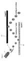
- Figure 1 shows schematically a droplet generating apparatus 2 for printing a fluid material 4.
- the apparatus 2 comprises a droplet generating head 12, constructed and arranged for printing a fluid with a printing pressure in at least a part of a channel upstream of the printing head, preferably in an interval of 0.1-3000 bars.
- a pressure system 40 is provided comprising a fluid inlet 41 and an outlet channel 42.
- the outlet channel 42 of the pressure system 40 connects with a damper 43.
- the outlet of the damper 43 is connected to the print head 12 via channel 10.
- the channel in the print head 12 is provided with at least one outflow opening, nozzle 14 through which the fluid material 4 exits under pressure in the form of a jet breaking up into drops, in order for these drops, after being selectively deflected, or directed, towards fluid jet 300.
- a transverse dimension of the nozzle 14 can be in the interval of 5-300 micron.
- the channel 10 comprises a portion downstream of the nozzle 14 which is provided with a cock 15.
- the printhead 12 can be flushed with a flushing material/flushing ink which is present in the channel.
- the illustrated apparatus 2 is a printer of the continuous jet-type, whereby a continuous stream of drops to be printed is formed.
- the invention may be also applicable in a drop-on-demand type printer system where drops are delivered through the outflow opening only if the printhead has been activated to that effect.
- the apparatus 2 is provided with a pressure regulating mechanism for varying the pressure of the material 4 upstream of the outflow opening.
- the apparatus 2 in this example may be provided with a pre-treatment system16.1, 16.2 enabling the drops to be pretreated.
- the pre-treatment system 16.1, 16.2 is provided, for instance, with a heater, cooler, a drying system, gas treatment, radiation treatment (UV treatment) by means of which the drops can be pretreated.
- the apparatus 2 may be provided with a collector 18 by which particular drops can be captured.
- the pressure generating means 40 may be constructed for providing a printing pressure in an interval of 0.1-3000 bars. Accordingly, high-viscous materials 4, for instance in a range of 0.1-800 mPa.s may be passed under a predetermined pressure through the channel in the direction of the nozzle 14. Under this pressure, viscous fluid 4 accommodated in the reservoir is forced through the channel 10 to the nozzle 14 in the printhead 12. Next, the viscous fluid 4 is forced through the nozzle 14 to the collector 18.
- the apparatus 2 according to Figure 1 is preferably provided with a heating element 34 for adjusting the viscous fluid 4 to a desired temperature.
- a heating element 34 for adjusting the temperature of the viscous fluid 4, the viscosity of the fluid can (to some extent) be (additionally) regulated.
- the heating element may be included in the printhead 12 in or near the channel 10.
- a second pressure system 20 comprising a second nozzle 140.
- the second nozzle 140 is arranged to generate a generally uninterrupted fluid jet 300.
- the second nozzle 140 is slitted to produce a sheet form or curtain form uninterrupted fluid jet having a relatively thin thickness of about several microns, preferably less than 1500 micron, to arrive at smaller thicknesses.
- a cross-section of the second nozzle 140 may be formed having broadened opposite sides.
- the second pressure system 20 is arranged to direct the fluid jet 300 at an angle relative to the direction of the beam of the isolated droplets 30 generated by the nozzle 14 of the fluid pressure system 2. In this way the fluid nozzle 14 and second nozzle 140 are arranged to have the isolated droplets 30 collide with fluid jet 300 generated by the second nozzle.
- a combined droplet is formed of the first fluid (in any phase state) with the second fluid of the fluid jet 300 to provide a multicomponent droplet.
- Printhead 120 of pressure system 20 is depicted with heating element 340; inlet channel 100; cock 150 and fluid material 400, to produce fluid jet 300.
- FIG 1 illustrates a collision of the droplets 30 with the fluid jet 300 in a transmissive mode, that is that the droplets 30 penetrate the fluid jet 300 from one side to the other side.
- figure 1 only illustrates a single nozzle system 14 for generating the droplets 30 a plurality of nozzles 14 can be provided to have a plurality of droplet beams collide with the fluid curtain formed by the second nozzle 140.
- a first embodiment is illustrated wherein droplets 30 are produced by nozzle 14 that are generally immiscible with fluid jet 300.
- a second fluid jet 310 is provided to illustrate the possibility of having colliding a droplet 30 with several fluid jets 300, 310 in order to form multilayer particles 31, 32 or particles comprised of a plurality of components.
- a "true encapsulation" of the droplets 30 with fluid jet material 300 is formed, optionally also by additional fluid jets 310 and higher.
- the droplets are formed as a core having an encapsulation formed around the core.
- complex multilayered / multimaterial particles 32 can be formed according to one aspect of the invention. Since the droplet generating arrangement 14 is of a continuous type this can produce higher volumes and will be interesting for industrial applications. It should be note that the droplets 30 are formed by ejecting a liquid but may become a solid before or after traversing fluid jet 300, for example pending on a preprocess 50 that may be performed on the droplets 30.
- Such pretreatment can be heating or cooling or drying or gas treatment or a radiation treatment, for example UV-treatment or any technique that may be feasible to pretreat the droplets 30 prior to colliding them with the fluid jet 300.
- Applications can be for example toner fillings or photography related applications or an application where uniform droplet sizes are of importance for example for providing solder paste.
- solder balls can be formed by emitting solder droplets and having them coated with the flux provided by a fluid jet. With this process solder balls can be coated with a small amount of flux to generate highly efficient solder paste.
- Another application can be in food, feed, pharma, cosmetics and other areas where a stabilization or protection of sensitive ingredients is needed. For example by encapsulating these with a permeation-limiting shell material.
- the fluid jet material can be chosen to provide a chemically protective encapsulation, or to provide a UV-protective encapsulation.
- the protection is designed against a unexpected chemical treat or physical treat of the ingredients, for example but not limited to UV-light, or oxygen, water, PH, ions or chemicals.
- the encapsulation can be provided to shield reactive ingredients, for example reactive polymers or glues or epoxy resins from environments.
- the first material is arranged to be chemically reactive with a for a predetermined environment parameter, for example but not limited to UV-light, oxygen, water, PH, ions or other chemicals. Degradation or rupturing of the encapsulation material may lead to release of the core material which would be able to provide materials that are self-repairing where such particles may be embedded in a matrix material or premixed two component glue.
- the first droplet material may stay in any desired phase depending on material parameters including gas phase, liquid phase or solid phase.
- liquids such as water maybe encapsulated by a solid encapsulation to provide particles filled with water. These might be used to generate instant ready meal without the need of adding extra water.
- the advantage of having encapsulated is that the water releases when it is necessary and not beforehand.
- the second material can be designed to have suitable material properties to have a predetermined permeability to the first material that is encapsulated inside to provide a time-delayed release of the first material.
- particles 31 can be made that can be used as slow or triggered release applications. By selecting a shell material that has a degree of permeability the payload can diffuse out of the particles with a diffusion rate depending on the permeability of the shell.
- a shell material can be selected that is impermeable until made permeable by a certain trigger (e.g. water, enzymes, pH, temperature, mechanical energy). This will then result in a release of the payload as described above.
- a certain trigger e.g. water, enzymes, pH, temperature, mechanical energy.
- a body cream may contain particles (e.g. perfume, deodorant) that, upon heating, rupture or melt to release an ingredient (e.g. menthol or ethanol), that will produce a cooling or soothing effect.
- particles e.g. perfume, deodorant
- an ingredient e.g. menthol or ethanol
- fragrances cosmetics, home care
- antibacterial paint, anti fouling coatings
- antioxidants food, feed
- the method can be extended to a collided droplet 31 with a further fluid jet 310.
- This provides a possibility to encapsulate two or more ingredients that need to be kept apart (e.g. to reactivity).
- An example may be two component glue: wherein a particle is ruptured, the two components are released and will react.
- Another example of a multiple layered particle may be a particle that is releasing one or more active ingredients in a time-delayed manner. That is each of the ingredients may be released by different or identical triggers which could be used to release various compounds in different parts of a digestive tract and responds to the presence of different enzymes present in the various parts of the digestive tract.
- a post-treatment step 51 can be performed such as heating, cooling, drying or gas treatment or any other UV treatment or other techniques to post process the particles 31.
- this may be aimed at providing a droplet that is immiscible with the fluid jet material in order to provide a well-defined encapsulation.
- This may equally apply to the encapsulation of liquefied gasses.
- the method provides a plurality of coated droplets that could be received on a substrate to provide a matrix of droplets having a predetermined interspacing.
- the dimension of the droplets can be very precisely controlled to form identical droplets.
- coloring effect can be generated by interference of light.
- particles can be distanced optically by having a transparent coating of a predetermined thickness. Placing these particles against each other provides a control distance between core particles.
- Other application could be providing encapsulated biomaterials such as cells or viruses.
- Another application could be even providing encapsulated solid objects such as plant seeds to have them coated with predetermined coating materials for example to provide antifungal or germination enhancing effects.
- Figure 3 shows a series of non-spherical droplets that can be provided by varying heat capacities and temperatures of the core material 30 and the fluid jet material 300.
- non-spherical particles can be obtained when providing droplets of water/glycol mixture through a molten paraffin or wax screen 300. Rather than spheres, elongated drops with a long tail were obtained as in Figure A.
- non-symmetrical aspect ratio can provide oriented or aligned particles 32 as in Figure 3 .
- the inner material can be made addressable, which may provide applications such as a controlled diffusion or release profile of the inner material out of the particles.
- removal of the interior material may provide interesting large areas structures, for example for use as catalysts or the like.
- Figure 4 shows a further aspect of the invention, wherein the droplet material 30 and the liquid jet material 300 are chosen to be of a miscible nature, to provide a mixed multicomponent droplet.
- the material 30 and 300 are mixed, which could result in emulsified, crystallized or gelated droplets, depending on the materials and conditions chosen, for example this set-up can provide micro-compartmentalized entities or microreactors, which can form a free environments wherein reactions or processes can be employed that are difficult to control in other set-ups due to strong heat effects and /or risks of explosion.
- the materials 30 and 300 may be a pure liquid or any other suitable forms of fluids that may already be mixed or emulsified or any other condition.
- droplets 30 comprise of e.g. an oil in ethanol
- shooting drops 30 through a screen 300 e.g. water
- a screen 300 e.g. water
- each ethanol/water droplet will contain an identical oil droplet. This means that this method can be used to make uniform oil droplets (or other particles) of a size that is not limited by the (lowest possible) size of the printer nozzle.
- Solidification of the small (inner) droplets might result in interesting nanomaterials, or particles that may have applications in heterogeneous catalysis.
- droplets 30 may comprise a solid compound (non-water-soluble) dissolved in ethanol.
- Printing drops of this solution through screen 300 e.g. water
- the size of the solid particles might well be very small, allowing the formation of nanoparticles or nanocrystals.
- the particle size might be very monodisperse. (Note: crystallization may also be induced by a change in pH, salt concentration or some other parameter.)
- the mixing of solution 1 and 2 may result in gelation of the particle.
- An example of this may be to print drop of a Na-alginate solution through a Ca2+ solution screen, thus producing microgel-particles.
- Microgel particles are being investigated widely for various applications ranging from drug delivery devices to environmental applications in which they may be used as nanosponges.
- a printing setup allows one to start with a relatively viscous solution (i.e. a concentrated polymer solution), resulting in gel particles with a very high solid content not easily attainable by other methods.
- a relatively viscous solution i.e. a concentrated polymer solution
- gels generally consist of two separate but each continuous phases, the removal of one of the two phases would result in a micro/macroporous material of well-defined size (monodisperse) that would have zeolite-like properties.
- a fourth embodiment 380 the mixing of several reactants by coalescence of droplets 31 and fluid jet 300 can be used to carry out chemical reactions.
- Each drop would function as a microreactor, giving many of the advantages for which microfluidic devices are currently being investigated. Heat effects and dangerous compounds would be easier to control, however, the continuous process would still allow the production of significant quantities of material.
- the mixing embodiments 350, 360, 370 and 380 can be used in addition to the encapsulation embodiment discussed in Figure 2 .
- the nozzle 14 illustrated in Figure 4 can be arranged to have the isolated droplets 30 collide with the fluid jet 300 in a reflective mode. It is possible to have a second fluid jet 310 parallel to first fluid jet to provide an additional reflective mode. In this way the isolated droplet 30 can be collided with one or more fluid jets to provide a non-symmetrical coating.
- a rapidly solidifying material may be used for providing droplets 30, resulting in bouncing of solid particles 30 of the surface of fluid jet 300. This may also be a material that solidifies rapidly or which may be a paint that is dried subsequently.
- the coating can be non-symmetric with respect to color, polarity, hydrophilic and/or surface chemistry characteristics resulting in different binding or reaction sites.
- One exemplary use can be as E-ink wherein particles are coated white and black on respective sides and can be addressed to show either white or black when in addition they are having a suitable polarity that can be oriented, for example by electrodes in a conventional way. This can result in higher resolution images since the particle size can be smaller than 250 micron. Also a plurality of colors, for example three different colored sides may be possible.
- Another application may be used of these asymmetric coated particles as macrosurfactants, for example for novel types of emulsion stabilizers or as compatibilizers for gluing of two different materials.
- particles can be made with different properties on each end, they may be applicable for us as material for coatings, and could for example convert hydrophobic surfaces to hydrophilic.
- they may be used as additives for self-stratifying layers.
- the polar part of the particles When for example embedded in apolar matrix, the polar part of the particles will make them diffuse to the surface.
- the shape of the particles and their organization in the layer can result in optical effects or a lotus effect.
- a method for generating a multicomponent droplet comprising generated at least one isolated droplet 30 of a first material, generating a generally uninterrupted fluid jet of a fluid jet 300 of a second material and colliding said isolated droplet 30 with the fluid jet 300 so as to combine said droplet of the first material with the second material.
- generally uninterrupted refers to a fluid jet, without dividing up into separate droplets, although more downstream this could be taking place without problems.
- the planarity of the fluid jet can be increased by having a cross-section of the fluid jet nozzle 140 in a slip form having broadened opposite sides.
- applied pressures can range from 0.1 - 3000 bars and applied temperatures can range from - 200 to + 1800 °C. Viscosities may range from 0.5 to 200 10 -3 Pa.s. upon exit.
- the term "fluid” may encompass, without limitation, a liquid or liquid mixtures; solutions; emulsions; dispersions or melts, and may include gasses or liquefied gasses.
- the invention has been described with fluid particles as embodiments, other types of particles may be applied likewise, such as solid grains or seeds etc. The invention has been described on the basis of an exemplary embodiment, but is not in any way limited to this embodiment. Diverse variations also falling within the scope of the invention are possible.
Landscapes
- Chemical & Material Sciences (AREA)
- Organic Chemistry (AREA)
- Chemical Kinetics & Catalysis (AREA)
- Physical Or Chemical Processes And Apparatus (AREA)
- Medicinal Preparation (AREA)
- Glanulating (AREA)
- Disintegrating Or Milling (AREA)
Priority Applications (9)
| Application Number | Priority Date | Filing Date | Title |
|---|---|---|---|
| EP07112887A EP2020261A1 (de) | 2007-07-20 | 2007-07-20 | System zur Erzeugung von Teilchen mit mehreren Komponenten |
| CA2694051A CA2694051A1 (en) | 2007-07-20 | 2008-07-07 | Multi component particle generating system |
| NZ583087A NZ583087A (en) | 2007-07-20 | 2008-07-07 | Multi component particle generating system: isolated particles colliding with an uninterupted fluid jet |
| TW97125514A TW200911387A (en) | 2007-07-20 | 2008-07-07 | Multi component particle generating system |
| PCT/NL2008/050456 WO2009014432A1 (en) | 2007-07-20 | 2008-07-07 | Multi component particle generating system |
| CN200880103748.7A CN101795758A (zh) | 2007-07-20 | 2008-07-07 | 多组分颗粒生成系统 |
| AU2008279870A AU2008279870B2 (en) | 2007-07-20 | 2008-07-07 | Multi component particle generating system |
| EP08766877A EP2180941A1 (de) | 2007-07-20 | 2008-07-07 | System zur bildung von mehrkomponentigen teilchen |
| US12/669,656 US8826848B2 (en) | 2007-07-20 | 2008-07-07 | Multi component particle generating system |
Applications Claiming Priority (1)
| Application Number | Priority Date | Filing Date | Title |
|---|---|---|---|
| EP07112887A EP2020261A1 (de) | 2007-07-20 | 2007-07-20 | System zur Erzeugung von Teilchen mit mehreren Komponenten |
Publications (1)
| Publication Number | Publication Date |
|---|---|
| EP2020261A1 true EP2020261A1 (de) | 2009-02-04 |
Family
ID=38777746
Family Applications (2)
| Application Number | Title | Priority Date | Filing Date |
|---|---|---|---|
| EP07112887A Withdrawn EP2020261A1 (de) | 2007-07-20 | 2007-07-20 | System zur Erzeugung von Teilchen mit mehreren Komponenten |
| EP08766877A Withdrawn EP2180941A1 (de) | 2007-07-20 | 2008-07-07 | System zur bildung von mehrkomponentigen teilchen |
Family Applications After (1)
| Application Number | Title | Priority Date | Filing Date |
|---|---|---|---|
| EP08766877A Withdrawn EP2180941A1 (de) | 2007-07-20 | 2008-07-07 | System zur bildung von mehrkomponentigen teilchen |
Country Status (8)
| Country | Link |
|---|---|
| US (1) | US8826848B2 (de) |
| EP (2) | EP2020261A1 (de) |
| CN (1) | CN101795758A (de) |
| AU (1) | AU2008279870B2 (de) |
| CA (1) | CA2694051A1 (de) |
| NZ (1) | NZ583087A (de) |
| TW (1) | TW200911387A (de) |
| WO (1) | WO2009014432A1 (de) |
Cited By (3)
| Publication number | Priority date | Publication date | Assignee | Title |
|---|---|---|---|---|
| EP2827287A1 (de) | 2013-07-15 | 2015-01-21 | Nederlandse Organisatie voor toegepast -natuurwetenschappelijk onderzoek TNO | Nachverfolgungs- und Spurenpoststück für Einschreiben und medizinische Umwicklung |
| WO2017167798A1 (en) * | 2016-03-30 | 2017-10-05 | Universiteit Twente | Process and device for in-air production of single droplets, compound droplets, and shape-controlled (compound) particles or fibers |
| WO2021260668A1 (en) | 2020-06-26 | 2021-12-30 | Iamfluidics Holding B.V. | Micro-fluidic system and method |
Families Citing this family (11)
| Publication number | Priority date | Publication date | Assignee | Title |
|---|---|---|---|---|
| EP2058131A1 (de) * | 2007-11-09 | 2009-05-13 | Nederlandse Organisatie voor toegepast- natuurwetenschappelijk onderzoek TNO | Tröpfchenauswahlmechanismus |
| EP2726870B1 (de) | 2011-06-29 | 2018-10-03 | Academia Sinica | Erfassung, reinigung und freisetzung eines biologischen stoffes anahnd einer oberflächenbeschichtung |
| CN104511399B (zh) * | 2013-09-30 | 2017-02-15 | 无锡华润安盛科技有限公司 | 点胶头装置 |
| US10016777B2 (en) * | 2013-10-29 | 2018-07-10 | Palo Alto Research Center Incorporated | Methods and systems for creating aerosols |
| US9962673B2 (en) * | 2013-10-29 | 2018-05-08 | Palo Alto Research Center Incorporated | Methods and systems for creating aerosols |
| TW201623605A (zh) | 2014-04-01 | 2016-07-01 | 中央研究院 | 用於癌症診斷及預後之方法及系統 |
| US10112198B2 (en) | 2014-08-26 | 2018-10-30 | Academia Sinica | Collector architecture layout design |
| GB2551944B (en) | 2015-12-18 | 2021-09-01 | Midatech Pharma Wales Ltd | Microparticle production process and apparatus |
| US10107726B2 (en) | 2016-03-16 | 2018-10-23 | Cellmax, Ltd. | Collection of suspended cells using a transferable membrane |
| US10850298B1 (en) * | 2016-05-06 | 2020-12-01 | Madeline A. Kuchinski | System for non-contact coating of moving component through a falling flow of coating material |
| CN115228317B (zh) * | 2022-07-05 | 2024-04-26 | 中国农业科学院烟草研究所(中国烟草总公司青州烟草研究所) | 一种烤烟种植用的肥药制备装置及方法 |
Citations (5)
| Publication number | Priority date | Publication date | Assignee | Title |
|---|---|---|---|---|
| GB2067908A (en) * | 1980-01-25 | 1981-08-05 | Neptune Microfloc Inc | Method and apparatus for wetting powder or granular material |
| WO1993011844A1 (en) * | 1991-12-17 | 1993-06-24 | Holm Christensen Boerge | A method for coated particles in a spray-drying plant |
| US5230735A (en) * | 1989-09-22 | 1993-07-27 | Nisshin Flour Milling Co., Ltd. | Apparatus for coating powder particles |
| EP0563402A1 (de) * | 1991-10-18 | 1993-10-06 | Freund Industrial Co., Ltd. | Beschichtungsvorrichtung |
| WO1994017941A1 (en) * | 1993-02-06 | 1994-08-18 | Osprey Metals Limited | Production of powder |
Family Cites Families (8)
| Publication number | Priority date | Publication date | Assignee | Title |
|---|---|---|---|---|
| US4341310A (en) * | 1980-03-03 | 1982-07-27 | United Technologies Corporation | Ballistically controlled nonpolar droplet dispensing method and apparatus |
| JPS62282658A (ja) | 1986-05-30 | 1987-12-08 | Sankyo:Kk | 多重シ−ムレスカプセル製造用の液滴ノズル |
| DK160809C (da) * | 1989-01-09 | 1995-10-02 | Niro Holding As | Fremgangsmåde og forstøvningstørringsapparat til fremstilling af stabile partikelagglomerater |
| JPH02282658A (ja) | 1989-04-24 | 1990-11-20 | Fujitsu General Ltd | ヒートポンプ式給湯機 |
| ES2180405B1 (es) | 2001-01-31 | 2004-01-16 | Univ Sevilla | Dispositivo y procedimiento para producir chorros liquidos compuestos multicomponentes estacionarios y capsulas multicomponente y/o multicapa de tamaño micro y nanometrico. |
| US7258428B2 (en) | 2004-09-30 | 2007-08-21 | Kimberly-Clark Worldwide, Inc. | Multiple head concentric encapsulation system |
| US20070003694A1 (en) * | 2005-05-23 | 2007-01-04 | Shivkumar Chiruvolu | In-flight modification of inorganic particles within a reaction product flow |
| TW200711809A (en) | 2005-05-23 | 2007-04-01 | Nanogram Corp | Nanostructured composite particles and corresponding processes |
-
2007
- 2007-07-20 EP EP07112887A patent/EP2020261A1/de not_active Withdrawn
-
2008
- 2008-07-07 US US12/669,656 patent/US8826848B2/en not_active Expired - Fee Related
- 2008-07-07 EP EP08766877A patent/EP2180941A1/de not_active Withdrawn
- 2008-07-07 NZ NZ583087A patent/NZ583087A/xx not_active IP Right Cessation
- 2008-07-07 AU AU2008279870A patent/AU2008279870B2/en not_active Ceased
- 2008-07-07 CA CA2694051A patent/CA2694051A1/en not_active Abandoned
- 2008-07-07 CN CN200880103748.7A patent/CN101795758A/zh active Pending
- 2008-07-07 WO PCT/NL2008/050456 patent/WO2009014432A1/en not_active Ceased
- 2008-07-07 TW TW97125514A patent/TW200911387A/zh unknown
Patent Citations (5)
| Publication number | Priority date | Publication date | Assignee | Title |
|---|---|---|---|---|
| GB2067908A (en) * | 1980-01-25 | 1981-08-05 | Neptune Microfloc Inc | Method and apparatus for wetting powder or granular material |
| US5230735A (en) * | 1989-09-22 | 1993-07-27 | Nisshin Flour Milling Co., Ltd. | Apparatus for coating powder particles |
| EP0563402A1 (de) * | 1991-10-18 | 1993-10-06 | Freund Industrial Co., Ltd. | Beschichtungsvorrichtung |
| WO1993011844A1 (en) * | 1991-12-17 | 1993-06-24 | Holm Christensen Boerge | A method for coated particles in a spray-drying plant |
| WO1994017941A1 (en) * | 1993-02-06 | 1994-08-18 | Osprey Metals Limited | Production of powder |
Cited By (9)
| Publication number | Priority date | Publication date | Assignee | Title |
|---|---|---|---|---|
| EP2827287A1 (de) | 2013-07-15 | 2015-01-21 | Nederlandse Organisatie voor toegepast -natuurwetenschappelijk onderzoek TNO | Nachverfolgungs- und Spurenpoststück für Einschreiben und medizinische Umwicklung |
| WO2017167798A1 (en) * | 2016-03-30 | 2017-10-05 | Universiteit Twente | Process and device for in-air production of single droplets, compound droplets, and shape-controlled (compound) particles or fibers |
| EP3791953A1 (de) * | 2016-03-30 | 2021-03-17 | IamFluidics Holding B.V. | Verfahren und vorrichtung zur herstellung in der luft von einzelnen tröpfchen, verbundenen tröpfchen und formgesteuerten (verbundenen) partikeln oder fasern |
| US11198293B2 (en) | 2016-03-30 | 2021-12-14 | Iamfluidics Holding B.V. | Process and device for in-air production of single droplets, compound droplets, and shape-controlled (compound) particles or fibers |
| EP4000724A1 (de) * | 2016-03-30 | 2022-05-25 | IamFluidics Holding B.V. | Verfahren und vorrichtung zur herstellung in der luft von einzelnen tröpfchen, verbundtröpfchen sowie formspeichernden (verbund)partikeln aus fasern |
| US11850851B2 (en) | 2016-03-30 | 2023-12-26 | Iamfluidics Holding B.V. | Process and device for in-air production of single droplets, compound droplets, and shape-controlled (compound) particles or fibers |
| US11850852B2 (en) | 2016-03-30 | 2023-12-26 | Iamfluidics Holding B.V. | Process and device for in-air production of single droplets, compound droplets, and shape-controlled (compound) particles or fibers |
| WO2021260668A1 (en) | 2020-06-26 | 2021-12-30 | Iamfluidics Holding B.V. | Micro-fluidic system and method |
| NL2025932B1 (en) | 2020-06-26 | 2022-02-21 | Iamfluidics Holding B V | Micro-fluidic system and method |
Also Published As
| Publication number | Publication date |
|---|---|
| US8826848B2 (en) | 2014-09-09 |
| WO2009014432A1 (en) | 2009-01-29 |
| US20100247760A1 (en) | 2010-09-30 |
| CA2694051A1 (en) | 2009-01-29 |
| AU2008279870A1 (en) | 2009-01-29 |
| TW200911387A (en) | 2009-03-16 |
| EP2180941A1 (de) | 2010-05-05 |
| CN101795758A (zh) | 2010-08-04 |
| AU2008279870B2 (en) | 2012-07-05 |
| NZ583087A (en) | 2012-09-28 |
Similar Documents
| Publication | Publication Date | Title |
|---|---|---|
| EP2020261A1 (de) | System zur Erzeugung von Teilchen mit mehreren Komponenten | |
| EP2143486A1 (de) | System zur Erzeugung von Teilchen mit mehreren Komponenten | |
| US6890592B2 (en) | Uniform microcapsules | |
| Spyropoulos et al. | Advances in membrane emulsification. Part A: recent developments in processing aspects and microstructural design approaches | |
| JP2005144356A (ja) | 微小流路構造体及びこれを用いた微小粒子製造方法 | |
| JP7031103B2 (ja) | エマルションを調製する方法 | |
| US20060071357A1 (en) | Method and apparatus for liquid microencapsulation with polymers using ultrasonic atomization | |
| JP5683796B2 (ja) | 微小構造体の製造方法およびマイクロリアクター | |
| EP2213366A1 (de) | System zur Erzeugung von Teilchen mit mehreren Komponenten | |
| EP3157659B1 (de) | Mischen von flüssigkeiten | |
| Martín-Banderas et al. | Making drops in microencapsulation processes | |
| RU2132224C1 (ru) | Способ микрокапсулирования твердых материалов и гидрофобных жидкостей | |
| WO2018083457A1 (en) | Microparticle production | |
| JP2005205338A (ja) | 単分散粒子の製造方法 | |
| JPH05212270A (ja) | マイクロカプセルの連続製造装置 | |
| JP3198151B2 (ja) | マイクロカプセルの連続製造法 | |
| Nie | Developing New Strategies for the Preparation of Micro-and Nano-structured Polymer Materials | |
| JP2014046226A (ja) | インクジェット法を用いた化学プロセス |
Legal Events
| Date | Code | Title | Description |
|---|---|---|---|
| PUAI | Public reference made under article 153(3) epc to a published international application that has entered the european phase |
Free format text: ORIGINAL CODE: 0009012 |
|
| AK | Designated contracting states |
Kind code of ref document: A1 Designated state(s): AT BE BG CH CY CZ DE DK EE ES FI FR GB GR HU IE IS IT LI LT LU LV MC MT NL PL PT RO SE SI SK TR |
|
| AX | Request for extension of the european patent |
Extension state: AL BA HR MK RS |
|
| AKX | Designation fees paid | ||
| REG | Reference to a national code |
Ref country code: DE Ref legal event code: 8566 |
|
| STAA | Information on the status of an ep patent application or granted ep patent |
Free format text: STATUS: THE APPLICATION IS DEEMED TO BE WITHDRAWN |
|
| 18D | Application deemed to be withdrawn |
Effective date: 20090805 |