EP2020274A1 - Appareil et procédé de réparation de pointes de surface portante - Google Patents
Appareil et procédé de réparation de pointes de surface portante Download PDFInfo
- Publication number
- EP2020274A1 EP2020274A1 EP08252546A EP08252546A EP2020274A1 EP 2020274 A1 EP2020274 A1 EP 2020274A1 EP 08252546 A EP08252546 A EP 08252546A EP 08252546 A EP08252546 A EP 08252546A EP 2020274 A1 EP2020274 A1 EP 2020274A1
- Authority
- EP
- European Patent Office
- Prior art keywords
- airfoil
- ceramic core
- internal cavity
- ceramic
- stub
- Prior art date
- Legal status (The legal status is an assumption and is not a legal conclusion. Google has not performed a legal analysis and makes no representation as to the accuracy of the status listed.)
- Withdrawn
Links
- 238000000034 method Methods 0.000 title claims abstract description 27
- 239000000919 ceramic Substances 0.000 claims abstract description 57
- 239000007769 metal material Substances 0.000 claims abstract description 15
- 238000003754 machining Methods 0.000 claims abstract description 5
- 239000000463 material Substances 0.000 claims description 45
- 239000002002 slurry Substances 0.000 claims description 13
- 238000001816 cooling Methods 0.000 claims description 5
- 238000002156 mixing Methods 0.000 claims description 4
- 239000000203 mixture Substances 0.000 claims description 3
- 229910000601 superalloy Inorganic materials 0.000 claims description 2
- 239000000758 substrate Substances 0.000 claims 6
- PXHVJJICTQNCMI-UHFFFAOYSA-N Nickel Chemical compound [Ni] PXHVJJICTQNCMI-UHFFFAOYSA-N 0.000 claims 2
- 229910052759 nickel Inorganic materials 0.000 claims 1
- 230000008439 repair process Effects 0.000 description 17
- 230000006378 damage Effects 0.000 description 12
- 239000007789 gas Substances 0.000 description 8
- 238000003466 welding Methods 0.000 description 7
- KWYUFKZDYYNOTN-UHFFFAOYSA-M Potassium hydroxide Chemical compound [OH-].[K+] KWYUFKZDYYNOTN-UHFFFAOYSA-M 0.000 description 3
- 229910045601 alloy Inorganic materials 0.000 description 2
- 239000000956 alloy Substances 0.000 description 2
- 239000012809 cooling fluid Substances 0.000 description 2
- 238000007730 finishing process Methods 0.000 description 2
- RTAQQCXQSZGOHL-UHFFFAOYSA-N Titanium Chemical compound [Ti] RTAQQCXQSZGOHL-UHFFFAOYSA-N 0.000 description 1
- 238000013019 agitation Methods 0.000 description 1
- 238000007664 blowing Methods 0.000 description 1
- 238000005266 casting Methods 0.000 description 1
- 229910010293 ceramic material Inorganic materials 0.000 description 1
- 238000000576 coating method Methods 0.000 description 1
- 239000010941 cobalt Substances 0.000 description 1
- 229910017052 cobalt Inorganic materials 0.000 description 1
- GUTLYIVDDKVIGB-UHFFFAOYSA-N cobalt atom Chemical compound [Co] GUTLYIVDDKVIGB-UHFFFAOYSA-N 0.000 description 1
- 239000012530 fluid Substances 0.000 description 1
- 238000010438 heat treatment Methods 0.000 description 1
- 239000011261 inert gas Substances 0.000 description 1
- 238000005495 investment casting Methods 0.000 description 1
- 238000004519 manufacturing process Methods 0.000 description 1
- 239000012768 molten material Substances 0.000 description 1
- 230000003685 thermal hair damage Effects 0.000 description 1
- 239000010936 titanium Substances 0.000 description 1
- 229910052719 titanium Inorganic materials 0.000 description 1
- WFKWXMTUELFFGS-UHFFFAOYSA-N tungsten Chemical compound [W] WFKWXMTUELFFGS-UHFFFAOYSA-N 0.000 description 1
- 239000010937 tungsten Substances 0.000 description 1
- 229910052721 tungsten Inorganic materials 0.000 description 1
- 239000011800 void material Substances 0.000 description 1
Images


Classifications
-
- B—PERFORMING OPERATIONS; TRANSPORTING
- B23—MACHINE TOOLS; METAL-WORKING NOT OTHERWISE PROVIDED FOR
- B23P—METAL-WORKING NOT OTHERWISE PROVIDED FOR; COMBINED OPERATIONS; UNIVERSAL MACHINE TOOLS
- B23P6/00—Restoring or reconditioning objects
- B23P6/002—Repairing turbine components, e.g. moving or stationary blades, rotors
- B23P6/007—Repairing turbine components, e.g. moving or stationary blades, rotors using only additive methods, e.g. build-up welding
-
- F—MECHANICAL ENGINEERING; LIGHTING; HEATING; WEAPONS; BLASTING
- F01—MACHINES OR ENGINES IN GENERAL; ENGINE PLANTS IN GENERAL; STEAM ENGINES
- F01D—NON-POSITIVE DISPLACEMENT MACHINES OR ENGINES, e.g. STEAM TURBINES
- F01D5/00—Blades; Blade-carrying members; Heating, heat-insulating, cooling or antivibration means on the blades or the members
- F01D5/005—Repairing methods or devices
-
- F—MECHANICAL ENGINEERING; LIGHTING; HEATING; WEAPONS; BLASTING
- F05—INDEXING SCHEMES RELATING TO ENGINES OR PUMPS IN VARIOUS SUBCLASSES OF CLASSES F01-F04
- F05D—INDEXING SCHEME FOR ASPECTS RELATING TO NON-POSITIVE-DISPLACEMENT MACHINES OR ENGINES, GAS-TURBINES OR JET-PROPULSION PLANTS
- F05D2230/00—Manufacture
- F05D2230/10—Manufacture by removing material
-
- F—MECHANICAL ENGINEERING; LIGHTING; HEATING; WEAPONS; BLASTING
- F05—INDEXING SCHEMES RELATING TO ENGINES OR PUMPS IN VARIOUS SUBCLASSES OF CLASSES F01-F04
- F05D—INDEXING SCHEME FOR ASPECTS RELATING TO NON-POSITIVE-DISPLACEMENT MACHINES OR ENGINES, GAS-TURBINES OR JET-PROPULSION PLANTS
- F05D2230/00—Manufacture
- F05D2230/20—Manufacture essentially without removing material
- F05D2230/23—Manufacture essentially without removing material by permanently joining parts together
- F05D2230/232—Manufacture essentially without removing material by permanently joining parts together by welding
- F05D2230/235—TIG or MIG welding
-
- F—MECHANICAL ENGINEERING; LIGHTING; HEATING; WEAPONS; BLASTING
- F05—INDEXING SCHEMES RELATING TO ENGINES OR PUMPS IN VARIOUS SUBCLASSES OF CLASSES F01-F04
- F05D—INDEXING SCHEME FOR ASPECTS RELATING TO NON-POSITIVE-DISPLACEMENT MACHINES OR ENGINES, GAS-TURBINES OR JET-PROPULSION PLANTS
- F05D2230/00—Manufacture
- F05D2230/40—Heat treatment
-
- Y—GENERAL TAGGING OF NEW TECHNOLOGICAL DEVELOPMENTS; GENERAL TAGGING OF CROSS-SECTIONAL TECHNOLOGIES SPANNING OVER SEVERAL SECTIONS OF THE IPC; TECHNICAL SUBJECTS COVERED BY FORMER USPC CROSS-REFERENCE ART COLLECTIONS [XRACs] AND DIGESTS
- Y10—TECHNICAL SUBJECTS COVERED BY FORMER USPC
- Y10T—TECHNICAL SUBJECTS COVERED BY FORMER US CLASSIFICATION
- Y10T29/00—Metal working
- Y10T29/49—Method of mechanical manufacture
- Y10T29/49229—Prime mover or fluid pump making
- Y10T29/49236—Fluid pump or compressor making
- Y10T29/49238—Repairing, converting, servicing or salvaging
Definitions
- the present invention relates to repairs to tip regions of airfoils for use with gas turbine engines.
- Airfoils for gas turbine engines are prone to wear and damage during use. Often, damage to blade airfoils occurs at the airfoil tip, that is, at the radially outward region of the airfoil. Damage can include cracks, burning, and other damage that makes repair desirable or necessary.
- airfoils include cooling features that help prevent thermal damage as a result of the high temperature present in gas turbine engines where the airfoils are installed.
- Such airfoils typically are "hollow” in the sense that they include a core formed by internal passageways that direct relatively cool fluid through the airfoil in a desired manner.
- These known core structures can include features such as trip strips, which are ridges in the blade that induce turbulence in cooling flows.
- Repair processes are known for repairing the tip of a damaged airfoil.
- the technique of "open core welding" involves welding the airfoil tip while blowing air through the airfoil core in order to utilize the generated air pressure to prevent weld material from entering the core.
- known methods such as open core welding are insufficient to make repairs where damage to the airfoil extends significantly into the airfoil core structures, such as where a crack or other damage extends all the way from an exterior surface of an airfoil into core structures of that airfoil, affecting those core structures. Damage that reaches the core structures is generally considered outside repairable limits according to known repair processes.
- open core welding does not permit complex internal core structures, like trip strips, to be preserved or rebuilt.
- a method of repairing an airfoil for a gas turbine engine includes removing a damaged portion of the airfoil at a radially outward tip of the airfoil, securing temporarily a portion of a ceramic core stub within an internal cavity of the airfoil, applying new metallic material to the airfoil covering an exposed portion of the ceramic core stub, machining the airfoil to remove an excess portion of the new metallic material, and removing the ceramic core stub from the internal cavity of the airfoil.
- the present invention relates to a method for repairing damage to components of gas turbine engines, and more particularly to repairing damage to tip regions of airfoils that are "hollow", that is, airfoils that have internal cooling passageways.
- the invention further relates to the structure of the repaired airfoil after a repair has been performed.
- FIG. 1 is a flow chart that illustrates an embodiment of the inventive repair method. Details of the repair process will be described with reference to FIGS. 2-8 .
- an initial step is to identify damage to a tip region of a selected airfoil (step 20). The tip region is located at a radially outward portion of the airfoil when installed in an engine.
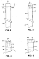
- FIG. 2 is a side view of a damaged airfoil 22 of a turbine blade 24 that has previously been in use in a gas turbine engine.
- the airfoil 22 includes a tip region 26 and a core 28.
- the airfoil 22 is formed of a metallic parent material, for example, a nickel- or cobalt-based superalloy, or titanium and alloys thereof.
- the term "parent material" refers to material of the airfoil 22 that has previously been in service, and can include original material as well as other material added during previous repairs.
- the core 28 provides at least one internal cooling passageway through the airfoil 22.
- the core 28 is illustrated as a monolithic void defined within the airfoil 22.
- the core 28 can include any number of internal passageways having any shape or arrangement to allow cooling fluid to flow through the airfoil 22.
- the core 28 can include internal features such as trip strips or other structures.
- the next step is to remove parent material at the tip region 26 of the airfoil 22 (step 30).
- the parent material is removed beyond a cut line 32.
- the amount of parent material removed that is, the location of the cut line 32, can vary as dictated by the amount of damage identified.
- the cut line 32 can be located at a standardized location that is radially inward of the damage to the tip region 26.
- removal of parent material at step 30 exposes the core 28 at the tip region 26 (and newly establishes a tip region 26A).
- the next step is to secure a ceramic core stub to the core 28 (step 33).
- ceramic core stub refers to a ceramic structure that resembles a portion of a structure that displaces molten material when originally casting the blade 24 to define the core 28.
- the ceramic core stub is a preformed structure that is inserted into the exposed core 28 of the airfoil 22 and secured there.
- the ceramic core stub has a shape that corresponds to a desired configuration of the core 28, and includes any internal features (e.g., trip strips) formed along the core 28.
- FIG. 3 is a side view of the blade 24 with a ceramic core stub 34 partially inserted into the core 28 of the airfoil 22.
- a portion of the ceramic core stub 34 generally protrudes from the core 28, radially outward from the location of the cut line 32 (see FIG. 2 ).
- the ceramic core stub 34 can be provided with one or more radially inwardly extending stumps 36 that are positioned to extend into the core 28.
- a ceramic slurry can be applied inside the core 28 of the airfoil 22 to adhere to the ceramic core stub 34 and better secure the ceramic core stub 34 to the core 28 (step 38).
- FIG. 4 is a side view of a portion of the airfoil 22 with a ceramic slurry 40 applied inside the core 28 to secure the ceramic core stub 34.
- the provision of the optional stumps 36 can enhance the effectiveness of the ceramic slurry 40 in securing the ceramic core stub 34 to the airfoil 22. Once the ceramic slurry 40 is applied, it can be hardened as desired.
- the hardened ceramic slurry 40 adhered to the ceramic core stub 34 can be considered to be a single structure for simplicity, and therefore the ceramic core stub 34, the stumps 36 and the ceramic slurry 40 are hereinafter collectively referred to as simply the ceramic core stub 34.
- FIG. 5 is a side view of a portion of the airfoil 22, showing new material 44 applied to the parent material of the airfoil 22 at the tip region 26A according to step 42.
- the new material 44 covers the ceramic core stub 34, effectively trapping it within the core 28 of the airfoil 22.
- the new material 44 forms a metallurgical bond with the parent material, and can be applied and built-up by a known welding technique, such as laser clad welding, tungsten inert gas (TIG) welding, or other suitable techniques.
- a known welding technique such as laser clad welding, tungsten inert gas (TIG) welding, or other suitable techniques.
- the new material 44 is applied to dimensions that are somewhat greater than the original airfoil 22 (i.e., greater than the blueprint specifications for the airfoil 22).
- the new material 44 can have a composition that is identical or similar to the composition of the parent material of the airfoil 22.
- the new material 44 can comprise an alloy that is more easily welded than the parent material of the airfoil 22. In some applications, it may be possible to use more easily weldable materials for the new material 44 when operational stresses are suitably low at the tip region 26A.
- FIG. 6 is a side view of a portion of the airfoil 22 after new material 44 is machined at a newly established tip region 26B to bring the airfoil 22 to a desired final spanwise dimension.
- FIG. 7 is a side view of a portion of the airfoil 22 after blending (step 48). At this stage during the repair process, the airfoil 22 has been restored to the desired final contour. However, the ceramic core stub 34 remains inside the core 28 of the airfoil 22.
- the ceramic core stub 34 is removed from the core 28 of the airfoil 22 using a known autoclave process (step 50).
- the ceramic core stub 34 is broken up and drawn out of the airfoil 22 in a manner similar to that performed during original fabrication and prior to use.
- the autoclave process can involve the use of Potassium Hydroxide, heat, pressure and agitation to break up and remove ceramic material of the ceramic core stub 34.
- Similar autoclave processes are used to remove the ceramic core from hollow investment castings (see, e.g., commonly-assigned U.S. Pat. No. 5,778,963 , which is hereby incorporated in full by reference).
- any desired finishing operations are performed (step 52).
- finishing processes include heat treatments, the reapplication of coatings, and other known processes.
- FIG. 8 is a side view of a portion of the airfoil 22 upon completion of the repair process of the present invention.
- the airfoil 22 is provided with a final contour, the ceramic core stub 34 has been removed such that the core 28 is open to permit cooling fluid to flow therethrough, and all finishing process have been performed.
Landscapes
- Engineering & Computer Science (AREA)
- Mechanical Engineering (AREA)
- General Engineering & Computer Science (AREA)
- Turbine Rotor Nozzle Sealing (AREA)
Applications Claiming Priority (1)
| Application Number | Priority Date | Filing Date | Title |
|---|---|---|---|
| US11/881,272 US20090028707A1 (en) | 2007-07-26 | 2007-07-26 | Apparatus and method for repairing airfoil tips |
Publications (1)
| Publication Number | Publication Date |
|---|---|
| EP2020274A1 true EP2020274A1 (fr) | 2009-02-04 |
Family
ID=39817017
Family Applications (1)
| Application Number | Title | Priority Date | Filing Date |
|---|---|---|---|
| EP08252546A Withdrawn EP2020274A1 (fr) | 2007-07-26 | 2008-07-25 | Appareil et procédé de réparation de pointes de surface portante |
Country Status (3)
| Country | Link |
|---|---|
| US (1) | US20090028707A1 (fr) |
| EP (1) | EP2020274A1 (fr) |
| SG (1) | SG149748A1 (fr) |
Families Citing this family (1)
| Publication number | Priority date | Publication date | Assignee | Title |
|---|---|---|---|---|
| US11814979B1 (en) * | 2022-09-21 | 2023-11-14 | Rtx Corporation | Systems and methods of hybrid blade tip repair |
Citations (5)
| Publication number | Priority date | Publication date | Assignee | Title |
|---|---|---|---|---|
| EP0269551A2 (fr) * | 1986-11-20 | 1988-06-01 | United Technologies Corporation | Procédés pour la réparation par soudage d'aubes normales et d'aubes fixes de turbines refroidi par air |
| US5778963A (en) | 1996-08-30 | 1998-07-14 | United Technologies Corporation | Method of core leach |
| EP1584702A1 (fr) * | 2004-04-06 | 2005-10-12 | United Technologies Corporation | Procédé de dépôt pour la réparation d'articles creux |
| EP1721696A1 (fr) * | 2005-05-06 | 2006-11-15 | United Technologies Corporation | Procédé pour réparer superalliage et inserts |
| EP1880793A2 (fr) * | 2006-07-20 | 2008-01-23 | Honeywell International Inc. | Réparation de l'extrémité d'une aube de turbine à haute pression simple avec placage laser |
Family Cites Families (11)
| Publication number | Priority date | Publication date | Assignee | Title |
|---|---|---|---|---|
| US2679669A (en) * | 1949-09-21 | 1954-06-01 | Thompson Prod Inc | Method of making hollow castings |
| US3576065A (en) * | 1969-03-24 | 1971-04-27 | Chromalloy American Corp | Repair of apertured machine components |
| US4023251A (en) * | 1975-07-30 | 1977-05-17 | General Electric Company | Method of manufacture of cooled turbine or compressor buckets |
| US4743462A (en) * | 1986-07-14 | 1988-05-10 | United Technologies Corporation | Method for preventing closure of cooling holes in hollow, air cooled turbine engine components during application of a plasma spray coating |
| GB8929005D0 (en) * | 1989-12-22 | 1990-02-28 | Refurbished Turbine Components | Turbine blade repair |
| US5511721A (en) * | 1994-11-07 | 1996-04-30 | General Electric Company | Braze blocking insert for liquid phase brazing operations |
| US5640767A (en) * | 1995-01-03 | 1997-06-24 | Gen Electric | Method for making a double-wall airfoil |
| DE19544293C2 (de) * | 1995-11-28 | 1998-01-29 | Degussa | Umhüllte Natriumpercarbonatpartikel und deren Verwendung |
| US5794338A (en) * | 1997-04-04 | 1998-08-18 | General Electric Company | Method for repairing a turbine engine member damaged tip |
| US6929054B2 (en) * | 2003-12-19 | 2005-08-16 | United Technologies Corporation | Investment casting cores |
| US20060248718A1 (en) * | 2005-05-06 | 2006-11-09 | United Technologies Corporation | Superalloy repair methods and inserts |
-
2007
- 2007-07-26 US US11/881,272 patent/US20090028707A1/en not_active Abandoned
-
2008
- 2008-05-22 SG SG200803869-7A patent/SG149748A1/en unknown
- 2008-07-25 EP EP08252546A patent/EP2020274A1/fr not_active Withdrawn
Patent Citations (5)
| Publication number | Priority date | Publication date | Assignee | Title |
|---|---|---|---|---|
| EP0269551A2 (fr) * | 1986-11-20 | 1988-06-01 | United Technologies Corporation | Procédés pour la réparation par soudage d'aubes normales et d'aubes fixes de turbines refroidi par air |
| US5778963A (en) | 1996-08-30 | 1998-07-14 | United Technologies Corporation | Method of core leach |
| EP1584702A1 (fr) * | 2004-04-06 | 2005-10-12 | United Technologies Corporation | Procédé de dépôt pour la réparation d'articles creux |
| EP1721696A1 (fr) * | 2005-05-06 | 2006-11-15 | United Technologies Corporation | Procédé pour réparer superalliage et inserts |
| EP1880793A2 (fr) * | 2006-07-20 | 2008-01-23 | Honeywell International Inc. | Réparation de l'extrémité d'une aube de turbine à haute pression simple avec placage laser |
Also Published As
| Publication number | Publication date |
|---|---|
| US20090028707A1 (en) | 2009-01-29 |
| SG149748A1 (en) | 2009-02-27 |
Similar Documents
| Publication | Publication Date | Title |
|---|---|---|
| US7966707B2 (en) | Method for repairing superalloy components using inserts | |
| EP1721697B2 (fr) | Procédé pour réparer superalliage et inserts | |
| US6173491B1 (en) | Method for replacing a turbine vane airfoil | |
| JP4375930B2 (ja) | タービンエンジン羽根の台板のレーザークラッディング | |
| CN100546756C (zh) | 修理单片叶片转盘的方法,起始和终了测试片 | |
| EP1759799B1 (fr) | Procédé de façonnage ou de refabrication d'éléments de moteur à turbine | |
| JP6157713B2 (ja) | 超合金部品の修復 | |
| EP2025864B1 (fr) | Réparation/remplacement de profil d' aube | |
| US9488053B2 (en) | Method for repairing a single crystal turbine blade | |
| US20130004320A1 (en) | Method of rotated airfoils | |
| EP1808266A2 (fr) | Réparation d'une plate-forme de turbine par placage laser | |
| JPH10339103A (ja) | タービンエンジン部材の損傷チップの補修方法 | |
| EP2159371B1 (fr) | Ensemble aubes de turbine à gaz et procédés de réparation | |
| EP1788196B1 (fr) | Procédé de la réparation d'un composant d'une turbine à gaz | |
| US20080201947A1 (en) | Method For Repairing Turbo Machine Blades | |
| EP2412930B1 (fr) | Segment statorique de turbine et son procédé de réparation | |
| EP2020274A1 (fr) | Appareil et procédé de réparation de pointes de surface portante | |
| US20220145765A1 (en) | Tip repair of a turbine component using a composite tip boron base pre-sintered preform |
Legal Events
| Date | Code | Title | Description |
|---|---|---|---|
| PUAI | Public reference made under article 153(3) epc to a published international application that has entered the european phase |
Free format text: ORIGINAL CODE: 0009012 |
|
| AK | Designated contracting states |
Kind code of ref document: A1 Designated state(s): AT BE BG CH CY CZ DE DK EE ES FI FR GB GR HR HU IE IS IT LI LT LU LV MC MT NL NO PL PT RO SE SI SK TR |
|
| AX | Request for extension of the european patent |
Extension state: AL BA MK RS |
|
| 17P | Request for examination filed |
Effective date: 20090512 |
|
| 17Q | First examination report despatched |
Effective date: 20090619 |
|
| AKX | Designation fees paid |
Designated state(s): DE GB |
|
| STAA | Information on the status of an ep patent application or granted ep patent |
Free format text: STATUS: THE APPLICATION IS DEEMED TO BE WITHDRAWN |
|
| 18D | Application deemed to be withdrawn |
Effective date: 20091030 |