EP2020292A2 - Rollenrotationsdruckmaschine - Google Patents
Rollenrotationsdruckmaschine Download PDFInfo
- Publication number
- EP2020292A2 EP2020292A2 EP08013301A EP08013301A EP2020292A2 EP 2020292 A2 EP2020292 A2 EP 2020292A2 EP 08013301 A EP08013301 A EP 08013301A EP 08013301 A EP08013301 A EP 08013301A EP 2020292 A2 EP2020292 A2 EP 2020292A2
- Authority
- EP
- European Patent Office
- Prior art keywords
- web
- printing
- partial
- printing material
- fed rotary
- Prior art date
- Legal status (The legal status is an assumption and is not a legal conclusion. Google has not performed a legal analysis and makes no representation as to the accuracy of the status listed.)
- Withdrawn
Links
Images
Classifications
-
- B—PERFORMING OPERATIONS; TRANSPORTING
- B41—PRINTING; LINING MACHINES; TYPEWRITERS; STAMPS
- B41F—PRINTING MACHINES OR PRESSES
- B41F7/00—Rotary lithographic machines
-
- B—PERFORMING OPERATIONS; TRANSPORTING
- B41—PRINTING; LINING MACHINES; TYPEWRITERS; STAMPS
- B41F—PRINTING MACHINES OR PRESSES
- B41F13/00—Common details of rotary presses or machines
- B41F13/02—Conveying or guiding webs through presses or machines
-
- B—PERFORMING OPERATIONS; TRANSPORTING
- B41—PRINTING; LINING MACHINES; TYPEWRITERS; STAMPS
- B41F—PRINTING MACHINES OR PRESSES
- B41F13/00—Common details of rotary presses or machines
- B41F13/02—Conveying or guiding webs through presses or machines
- B41F13/03—Threading webs into printing machines
-
- B—PERFORMING OPERATIONS; TRANSPORTING
- B41—PRINTING; LINING MACHINES; TYPEWRITERS; STAMPS
- B41F—PRINTING MACHINES OR PRESSES
- B41F13/00—Common details of rotary presses or machines
- B41F13/02—Conveying or guiding webs through presses or machines
- B41F13/06—Turning-bar arrangements
-
- B—PERFORMING OPERATIONS; TRANSPORTING
- B41—PRINTING; LINING MACHINES; TYPEWRITERS; STAMPS
- B41F—PRINTING MACHINES OR PRESSES
- B41F13/00—Common details of rotary presses or machines
- B41F13/08—Cylinders
- B41F13/24—Cylinder-tripping devices; Cylinder-impression adjustments
- B41F13/26—Arrangement of cylinder bearings
- B41F13/30—Bearings mounted on sliding supports
-
- B—PERFORMING OPERATIONS; TRANSPORTING
- B41—PRINTING; LINING MACHINES; TYPEWRITERS; STAMPS
- B41F—PRINTING MACHINES OR PRESSES
- B41F13/00—Common details of rotary presses or machines
- B41F13/08—Cylinders
- B41F13/24—Cylinder-tripping devices; Cylinder-impression adjustments
- B41F13/34—Cylinder lifting or adjusting devices
- B41F13/38—Cylinder lifting or adjusting devices electrically or magnetically operated
-
- B—PERFORMING OPERATIONS; TRANSPORTING
- B41—PRINTING; LINING MACHINES; TYPEWRITERS; STAMPS
- B41F—PRINTING MACHINES OR PRESSES
- B41F13/00—Common details of rotary presses or machines
- B41F13/54—Auxiliary folding, cutting, collecting or depositing of sheets or webs
- B41F13/56—Folding or cutting
Definitions
- the invention relates to a web-fed rotary printing press according to the preamble of claim 1.
- a web-fed rotary press has several printing units for printing at least one printing material web.
- several printing units in the form of printing towers are usually positioned vertically one above the other.
- the web-fed rotary printing press has a folding apparatus, wherein in the area of the folder of the or each printing material copies are separated by transverse cutting.
- the folder is used to form at least one transverse fold and / or at least one longitudinal fold on the separated copies.
- a so-called reversing and folding structure is positioned, wherein at least one printing material web can be separated into partial webs by longitudinal cutting in the region of the turning and folding structure.
- the or each printing material web or the or each partial web can be fed via turning bars and / or guide rolls to at least one former of the turning and folding structure.
- the present invention is based on the problem to provide a novel web-fed rotary printing press.
- This problem is solved by a web-fed rotary printing press according to claim 1.
- at least one guide roller is positioned along the transport path of the or each printing material web and / or the or each partial web by the turning and folding structure, whose both ends are each assigned an adjusting unit via which the respective end of the respective guide roll in and / or opposite is linearly displaceable to the direction of the respective substrate web or sub-web, namely such that either both ends of the respective guide roller uniformly to influence the cut register or both ends of the respective guide roll non-uniformly to influence the edge position of the respective printing substrate or partial web are displaced.
- the control of the cut register and the regulation of the web edge position of the or each printing material or the or each sub-web is realized in common by at least one guide roller.
- Section control and web edge control are therefore not realized in the printing machine according to the invention by separate units, but rather combined in one unit. As a result, space can be saved.
- Each adjustment unit is preferably designed as an electromotive actuator, in particular as an electromotive linear drive.
- the present invention relates to a web-fed rotary printing press having a plurality of printing units for printing at least one printing material web and a folding apparatus.
- copies can be separated by cross cutting from the or each printing material web.
- at least one longitudinal fold and / or at least one transverse fold can be formed in the area of the folding apparatus.
- a so-called turning and folding structure is positioned between the printing units and the folder.
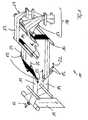
- Fig. 1 shows a section of a web-fed rotary printing press in the region of a turning structure 10, wherein in the region of the turning structure 10 of the Fig. 1 a printed substrate web 11 by means of a cutting device 12 by longitudinal cutting into two partial webs 13, 14 is separated.
- the partial webs 13, 14 are fed via guide rollers 15, 16 a former 17 of the folding structure 10 downstream of the folding structure 18.
- longitudinal folds are formed on the partial webs 13, 14 seen in the transport direction of the partial webs 13, 14, downstream of the former 17 are separated by cross cutting of the partial webs 13, 14 and thus of the printing substrate 11 copies.
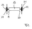
- At least one guide roller 15 is positioned along the transport path of the two partial webs 13, 14, whose two ends 19, 20 each have an adjusting unit 21 (see FIG Fig. 2 ) is assigned, via which the respective end 19, 20 of the respective guide roller 15 in or opposite to the direction of the respective partial web 13, 14 is linearly displaceable.
- the linear displaceability of the ends 19, 20 of the guide rollers 15 is in Fig. 1 . 2 visualized by arrows 22.
- each guide roller 15 the ends 19, 20 via the corresponding adjusting units 21 either uniformly for influencing or regulating the cut register or non-uniform for influencing or regulating the edge position of the respective partial web 13, 14 displaced.
- guide roller 15 therefore serves on the one hand the web edge control and on the other hand, the cut register control.
- the adjusting unit 21 associated with each guide roller 15 are either uniformly or non-uniformly controlled to linearly shift the respective ends 19, 20 of the respective guide roller 15 either uniformly or non-uniformly in the direction or opposite to the direction of the respective partial web 13, 14.
- Each adjustment unit 21 is preferably designed as an electromotive actuator, in particular as an electromotive linear drive. This allows a shift of the guide rollers 15 with a high dynamic, so that a simultaneous, dynamic control of cutting register and lateral edge position of the respective sub-web or substrate web is possible.
- Fig. 1 shows a possible embodiment of a turning structure 10, which is associated with at least one adjusting unit 15 for each partial web 13, 14.
- the invention is not limited to this specific application. Rather, the invention can also be used in web-fed rotary printing presses with other turning assemblies and folder superstructures.
Landscapes
- Engineering & Computer Science (AREA)
- Mechanical Engineering (AREA)
- Folding Of Thin Sheet-Like Materials, Special Discharging Devices, And Others (AREA)
- Rotary Presses (AREA)
Abstract
Description
- Die Erfindung betrifft eine Rollenrotationsdruckmaschine nach dem Oberbegriff des Anspruchs 1.
- Eine Rollenrotationsdruckmaschine verfügt über mehrere Druckeinheiten zum Bedrucken mindestens einer Bedruckstoffbahn. Bei Zeitungsdruckmaschinen sind üblicherweise mehrere Druckeinheiten in Form von Drucktürmen vertikal übereinander positioniert. In Transportrichtung der oder jeder Bedruckstoffbahn gesehen stromabwärts der Druckeinheiten verfügt die Rollenrotationsdruckmaschine über einen Falzapparat, wobei im Bereich des Falzapparats von der oder jeder Bedruckstoffbahn Exemplare durch Querschneiden abgetrennt werden. Weiterhin dient der Falzapparat der Ausbildung mindestens eines Querfalzes und/oder mindestens eines Längsfalzes an den abgetrennten Exemplaren. Zwischen den Druckeinheiten und dem Falzapparat der Rollenrotationsdruckmaschine ist ein sogenannter Wende- und Falzaufbau positioniert, wobei im Bereich des Wende- und Falzaufbaus mindestens eine Bedruckstoffbahn durch Längsschneiden in Teilbahnen getrennt werden kann. Alternativ oder zusätzlich hierzu sind die oder jede Bedruckstoffbahn bzw. die oder jede Teilbahn über Wendestangen und/oder Leitwalzen mindestens einem Falztrichter des Wende- und Falzaufbaus zuführbar.
- Aus der Praxis bekannte Rollenrotationsdruckmaschinen verfügen sowohl über eine Einrichtung zur Schnittregisterregelung als auch über eine Einrichtung zur Bahnkantenregelung, wobei nach der Praxis diese Einrichtungen als separate Aggregate ausgeführt sind, die unabhängig voneinander entlang des Transportwegs der oder jeder Bedruckstoffbahn bzw. der oder jeder Teilbahn vorzugsweise im Bereich des Wende- und Falzaufbaus positioniert sind. Hierdurch wird relativ viel Bauraum benötigt.
- Hiervon ausgehend liegt der vorliegenden Erfindung das Problem zugrunde, eine neuartige Rollenrotationsdruckmaschine zu schaffen. Dieses Problem wird durch eine Rollenrotationsdruckmaschine gemäß Anspruch 1 gelöst. Erfindungsgemäß ist entlang des Transportwegs der oder jeder Bedruckstoffbahn und/oder der oder jeder Teilbahn durch den Wende- und Falzaufbau jeweils mindestens eine Leitwalze positioniert, deren beider Enden jeweils eine Verstelleinheit zugeordnet ist, über die das jeweilige Ende der jeweiligen Leitwalze in und/oder entgegengesetzt zur Laufrichtung der jeweiligen Bedruckstoffbahn oder Teilbahn linear verlagerbar ist, nämlich derart, dass entweder beide Enden der jeweiligen Leitwalze gleichförmig zur Beeinflussung des Schnittregisters oder beide Enden der jeweiligen Leitwalze ungleichförmig zur Beeinflussung der Kantenlage der jeweiligen Bedruckstoffbahn oder Teilbahn verlagerbar sind.
- Bei der erfindungsgemäßen Druckmaschine wird die Regelung des Schnittregisters sowie die Regelung der Bahnkantenlage der oder jeder Bedruckstoffbahn bzw. der oder jeder Teilbahn gemeinsam von jeweils mindestens einer Leitwalze realisiert. Schnittregisterregelung sowie Bahnkantenregelung sind demnach bei der erfindungsgemäßen Druckmaschine nicht durch getrennte Aggregate realisiert, sondern vielmehr in einem Aggregat kombiniert. Hierdurch kann Bauraum eingespart werden.
- Vorzugsweise ist jede Verstelleinheit als elektromotorischer Aktuator, insbesondere als elektromotorischer Linearantrieb, ausgebildet.
- Bevorzugte Weiterbildungen der Erfindung ergeben sich aus den Unteransprüchen und der nachfolgenden Beschreibung. Ausführungsbeispiele der Erfindung werden an Hand der Zeichnung näher erläutert. Dabei zeigt:
- Fig. 1:
- einen schematisierten Ausschnitt aus einem Ausführungsbeispiel einer erfindungsgemäßen Rollenrotationsdruckmaschine, und
- Fig. 2:
- ein Detail der Anordnung gemäß
Fig. 1 . - Die hier vorliegende Erfindung betrifft eine Rollenrotationsdruckmaschine, die mehrere Druckeinheiten zum Bedrucken mindestens einer Bedruckstoffbahn und einem Falzapparat aufweist. Im Bereich des Falzapparats sind durch Querschneiden von der oder jeder Bedruckstoffbahn Exemplare abtrennbar. Weiterhin ist im Bereich des Falzapparats mindestens ein Längsfalz und/oder mindestens ein Querfalz ausbildbar. Zwischen den Druckeinheiten und dem Falzapparat ist ein sogenannter Wende- und Falzaufbau positioniert.
-
Fig. 1 zeigt einen Ausschnitt aus einer Rollenrotationsdruckmaschine im Bereich eines Wendeaufbaus 10, wobei im Bereich des Wendeaufbaus 10 derFig. 1 eine bedruckte Bedruckstoffbahn 11 mit Hilfe einer Schneideinrichtung 12 durch Längsschneiden in zwei Teilbahnen 13, 14 getrennt wird. Die Teilbahnen 13, 14 sind über Leitwalzen 15, 16 einem Falztrichter 17 eines dem Wendeaufbau 10 nachgeordneten Falzaufbaus 18 zuführbar. Im Bereich der Falztrichter 17 werden an den Teilbahnen 13, 14 Längsfalze ausgebildet, wobei in Transportrichtung der Teilbahnen 13, 14 gesehen, stromabwärts der Falztrichter 17 durch Querschneiden von den Teilbahnen 13, 14 und damit von der Bedruckstoffbahn 11 Exemplare abgetrennt werden. - Im Sinne der hier vorliegenden Erfindung ist entlang des Transportwegs der beiden Teilbahnen 13, 14 jeweils mindestens eine Leitwalze 15 positioniert, deren beider Enden 19, 20 jeweils eine Verstelleinheit 21 (siehe
Fig. 2 ) zugeordnet ist, über die das jeweilige Ende 19, 20 der jeweiligen Leitwalze 15 in bzw. entgegengesetzt zur Laufrichtung der jeweiligen Teilbahn 13, 14 linear verlagerbar ist. Die lineare Verlagerbarkeit der Enden 19, 20 der Leitwalzen 15 ist inFig. 1 ,2 durch Pfeile 22 visualisiert. - Erfindungsgemäß sind an jeder Leitwalze 15 die Enden 19, 20 über die entsprechenden Verstelleinheiten 21 entweder gleichförmig zur Beeinflussung oder Regelung des Schnittregisters oder ungleichförmig zur Beeinflussung bzw. Regelung der Kantenlage der jeweiligen Teilbahn 13, 14 verlagerbar. Jede auf die obige Art und Weise ausgebildete Leitwalze 15 dient demnach einerseits der Bahnkantenregelung und andererseits der Schnittregisterregelung. Die jeder Leitwalze 15 zugeordneten Verstelleinheiten 21 sind entweder gleichförmig oder ungleichförmig ansteuerbar, um die entsprechenden Enden 19, 20 der jeweiligen Leitwalze 15 entweder gleichförmig oder ungleichförmig in Laufrichtung bzw. entgegengesetzt zur Laufrichtung der jeweiligen Teilbahn 13, 14 linear zu verlagern.
- Jede Verstelleinheit 21 ist vorzugsweise als elektromotorischer Aktuator, insbesondere als elektromotorischer Linearantrieb, ausgebildet. Dies erlaubt eine Verlagerung der Leitwalzen 15 mit einer hohen Dynamik, sodass eine gleichzeitige, dynamische Regelung von Schnittregister und seitlicher Kantenlage der jeweiligen Teilbahn bzw. Bedruckstoffbahn möglich ist.
-
Fig. 1 zeigt eine mögliche Ausgestaltung eines Wendeaufbaus 10, dem für jede Teilbahn 13, 14 mindestens eine Verstelleinheit 15 zugeordnet ist. Die Erfindung ist nicht auf diesem konkreten Anwendungsfall beschränkt. Vielmehr kann die Erfindung auch bei Rollenrotationsdruckmaschinen mit anderen Wendeaufbauten und Falzaufbauten zum Einsatz kommen.
Claims (4)
- Rollenrotationsdruckmaschine, mit mehreren Druckeinheiten zum Bedrucken mindestens einer Bedruckstoffbahn, und mit einem Falzapparat, um von der oder jeder Bedruckstoffbahn durch Querschneiden Exemplare abzutrennen und mindestens einen Längsfalz und/oder mindestens einen Querfalz auszubilden, und mit einem zwischen den Druckeinheiten und dem Falzapparat positionierten Wende- und Falzaufbau, in welchem mindestens eine Bedruckstoffbahn durch Längsschneiden in Teilbahnen trennbar ist und/oder in welchen die oder jede Bedruckstoffbahn bzw. die oder jede Teilbahn über Wendestangen und/oder Leitwalzen mindestens einem Falztrichter zuführbar ist, dadurch gekennzeichnet, dass entlang des Transportwegs der oder jeder Bedruckstoffbahn und/oder der oder jeder Teilbahn durch den Wende- und Falzaufbau jeweils mindestens eine Leitwalze (15) positioniert ist, deren beider Enden (19, 20) jeweils eine Verstelleinheit (21) zugeordnet ist, über die das jeweilige Ende (19, 20) der jeweiligen Leitwalze (15) in und/oder entgegengesetzt zur Laufrichtung der jeweiligen Bedruckstoffbahn oder Teilbahn linear verlagerbar ist, nämlich derart, dass entweder beide Enden (19, 20) der jeweiligen Leitwalze (15) gleichförmig zur Beeinflussung des Schnittregisters oder beide Enden (19, 20) der jeweiligen Leitwalze (15) ungleichförmig zur Beeinflussung der Kantenlage der jeweiligen Bedruckstoffbahn oder Teilbahn verlagerbar sind.
- Rollenrotationsdruckmaschine nach Anspruch 1, dadurch gekennzeichnet, dass jede Verstelleinheit (21) als elektromotorischer Aktuator ausgebildet ist.
- Rollenrotationsdruckmaschine nach Anspruch 2, dadurch gekennzeichnet, dass jede Verstelleinheit (21) als elektromotorischer Linearantrieb ausgebildet ist.
- Rollenrotationsdruckmaschine nach einem der Ansprüche 1 bis 3, dadurch gekennzeichnet, dass jede Verstelleinheit (21) dem Wendeaufbau (10) zugeordnet ist.
Applications Claiming Priority (1)
| Application Number | Priority Date | Filing Date | Title |
|---|---|---|---|
| DE102007035432A DE102007035432A1 (de) | 2007-07-28 | 2007-07-28 | Rollenrotationsdruckmaschine |
Publications (2)
| Publication Number | Publication Date |
|---|---|
| EP2020292A2 true EP2020292A2 (de) | 2009-02-04 |
| EP2020292A3 EP2020292A3 (de) | 2011-07-27 |
Family
ID=40002940
Family Applications (1)
| Application Number | Title | Priority Date | Filing Date |
|---|---|---|---|
| EP08013301A Withdrawn EP2020292A3 (de) | 2007-07-28 | 2008-07-24 | Rollenrotationsdruckmaschine |
Country Status (6)
| Country | Link |
|---|---|
| US (1) | US20090025586A1 (de) |
| EP (1) | EP2020292A3 (de) |
| JP (1) | JP2009029129A (de) |
| KR (1) | KR20090012104A (de) |
| CN (1) | CN101372166A (de) |
| DE (1) | DE102007035432A1 (de) |
Families Citing this family (4)
| Publication number | Priority date | Publication date | Assignee | Title |
|---|---|---|---|---|
| DE102010053373A1 (de) * | 2010-12-03 | 2012-06-06 | Manroland Ag | Falzeinrichtung |
| JP2016104534A (ja) * | 2014-12-01 | 2016-06-09 | 株式会社ハナガタ | 気泡緩衝材用包装装置 |
| CN105668303B (zh) * | 2016-03-10 | 2018-07-24 | 金华市胜昌机械有限公司 | 春联折叠机 |
| CN106743965B (zh) * | 2017-03-29 | 2018-04-27 | 广州乐言玩具有限公司 | 一种具有自动切断机构的布料对折装置 |
Family Cites Families (16)
| Publication number | Priority date | Publication date | Assignee | Title |
|---|---|---|---|---|
| US2797091A (en) * | 1955-08-05 | 1957-06-25 | Irwin L Fife | Web shifting apparatus |
| US3595459A (en) * | 1969-11-04 | 1971-07-27 | Paul V Colombo | Guider for straightening traveling webs |
| DD234644A1 (de) * | 1985-02-14 | 1986-04-09 | Polygraph Leipzig | Vorrichtung zur regelung der bahnlage |
| DE3816900C1 (de) * | 1988-05-18 | 1989-11-16 | Man Roland Druckmaschinen Ag, 6050 Offenbach, De | |
| JP2751559B2 (ja) * | 1990-04-19 | 1998-05-18 | 三菱電機株式会社 | エンジンの燃料制御装置 |
| DE4013229C1 (de) * | 1990-04-26 | 1991-11-07 | Man Roland Druckmaschinen Ag, 6050 Offenbach, De | |
| EP0582927B1 (de) * | 1992-08-10 | 1997-11-19 | KOENIG & BAUER-ALBERT AKTIENGESELLSCHAFT | Wendestange für Materialbahnen |
| WO2000024526A1 (en) * | 1998-10-23 | 2000-05-04 | Musashi Engineering, Inc. | Liquid constant rate discharge method and device |
| EP1080887A1 (de) * | 1999-08-19 | 2001-03-07 | Quad/Tech, Inc. | Bahnlagekontrollsystem |
| US6705220B2 (en) * | 2001-06-22 | 2004-03-16 | Heidelberger Druckmaschinen Ag | Device for guiding a travelling web |
| DE10234674B4 (de) * | 2002-07-30 | 2010-04-29 | Wifag Maschinenfabrik Ag | Bahnspreizvorrichtung |
| DE10236657A1 (de) * | 2002-08-09 | 2004-02-26 | Maschinenfabrik Wifag | Schnittregister-Einstellvorrichtung |
| DE10236658B4 (de) * | 2002-08-09 | 2012-11-29 | Wifag Maschinenfabrik Ag | Schnittregister-Aufteilung |
| DE10337248B4 (de) * | 2003-08-13 | 2009-12-17 | Maschinenfabrik Wifag | Bahnspreizverfahren und Bahnspreizvorrichtung |
| DE102004022074B4 (de) * | 2004-05-05 | 2010-02-04 | Manroland Ag | Rollendruckmaschine |
| DE102004051263A1 (de) * | 2004-10-21 | 2006-04-27 | Man Roland Druckmaschinen Ag | Druckmaschinenanordnung |
-
2007
- 2007-07-28 DE DE102007035432A patent/DE102007035432A1/de not_active Withdrawn
-
2008
- 2008-07-23 KR KR1020080071557A patent/KR20090012104A/ko not_active Withdrawn
- 2008-07-23 JP JP2008190312A patent/JP2009029129A/ja active Pending
- 2008-07-24 EP EP08013301A patent/EP2020292A3/de not_active Withdrawn
- 2008-07-25 US US12/180,351 patent/US20090025586A1/en not_active Abandoned
- 2008-07-28 CN CNA2008102147081A patent/CN101372166A/zh active Pending
Also Published As
| Publication number | Publication date |
|---|---|
| KR20090012104A (ko) | 2009-02-02 |
| CN101372166A (zh) | 2009-02-25 |
| JP2009029129A (ja) | 2009-02-12 |
| DE102007035432A1 (de) | 2009-01-29 |
| US20090025586A1 (en) | 2009-01-29 |
| EP2020292A3 (de) | 2011-07-27 |
Similar Documents
| Publication | Publication Date | Title |
|---|---|---|
| EP1990190B1 (de) | Rollendruckmaschine | |
| EP1072551A2 (de) | Falzapparatanordnung in einer Rollenrotations-Zeitungs-druckmaschine | |
| EP1106554A2 (de) | Bewegbarer Falzapparat und Falzrichteranordnung | |
| EP1820644A2 (de) | Rollenrotationsdruckmaschine mit einem Druckturm | |
| EP2305468A1 (de) | Formatvariable Rollendruckmaschine | |
| EP1265803A1 (de) | Wendestangenanordnung und verfahren zum umlenken einer warenbahn | |
| CH688137A5 (de) | Rotations-Rollendruckmaschine mit einer Registervorrichtung zum Ausrichten der Papierbahn. | |
| DE4327646C2 (de) | Breiten-Einstellverfahren für eine Papierbahn sowie damit ausgerüstete lithographische Rotationspresse | |
| EP1634833B1 (de) | Druckmaschine mit mindestens einem Druckwerk | |
| EP2065191A2 (de) | Rollendruckmaschine | |
| WO2005105445A1 (de) | Druckformen einer druckmaschine und rollenrotationsdruckmaschinen | |
| EP1528982A1 (de) | Druckmaschinen mit mehreren druckwerken | |
| WO2009062745A1 (de) | Rollendruckmaschine | |
| EP2020292A2 (de) | Rollenrotationsdruckmaschine | |
| DE102005034331B4 (de) | Rollenrotationsdruckmaschine | |
| DE10164778A1 (de) | Vorrichtung zur Herstellung von Falzprodukten | |
| DE102005036451B4 (de) | Vorrichtung zur Erzeugung eines Produktabschnittes in einer bahnverarbeitenden Maschine | |
| DE102007030844A1 (de) | Rollenrotationsdruckmaschine, insbesondere Tiefdruckmaschine, mit halbbreiter Bedruckstoffbahn | |
| DE10119415A1 (de) | Schwertfalzwerk mit durchgehendem Vorderkantenanschlag und verstellbaren Seitenkantenanschlägen | |
| DE102009000295A1 (de) | Rollendruckmaschine | |
| EP1632348B1 (de) | Oberbau einer Druckmaschine mit Längsregistereinrichtungen sowie Druckmaschine | |
| EP1772264B1 (de) | Rotationsdruckmaschine mit Längsdehnungs-Kompensator für längsgeschnittene Bahn und Verfahren zum Bedrucken der längsgeschnittenen Bahn | |
| DE102012013002A1 (de) | Rollendruckmaschine | |
| DE10163211C2 (de) | Vorrichtung zur Herstellung von Falzprodukten | |
| EP2028147A2 (de) | Verfahren zum Betreiben einer Rollendruckmaschine |
Legal Events
| Date | Code | Title | Description |
|---|---|---|---|
| PUAI | Public reference made under article 153(3) epc to a published international application that has entered the european phase |
Free format text: ORIGINAL CODE: 0009012 |
|
| AK | Designated contracting states |
Kind code of ref document: A2 Designated state(s): AT BE BG CH CY CZ DE DK EE ES FI FR GB GR HR HU IE IS IT LI LT LU LV MC MT NL NO PL PT RO SE SI SK TR |
|
| AX | Request for extension of the european patent |
Extension state: AL BA MK RS |
|
| PUAL | Search report despatched |
Free format text: ORIGINAL CODE: 0009013 |
|
| AK | Designated contracting states |
Kind code of ref document: A3 Designated state(s): AT BE BG CH CY CZ DE DK EE ES FI FR GB GR HR HU IE IS IT LI LT LU LV MC MT NL NO PL PT RO SE SI SK TR |
|
| AX | Request for extension of the european patent |
Extension state: AL BA MK RS |
|
| RIC1 | Information provided on ipc code assigned before grant |
Ipc: B41F 13/56 20060101ALI20110622BHEP Ipc: B41F 13/30 20060101ALI20110622BHEP Ipc: B41F 13/06 20060101ALI20110622BHEP Ipc: B41F 13/02 20060101AFI20081209BHEP |
|
| 19U | Interruption of proceedings before grant |
Effective date: 20120201 |
|
| AKY | No designation fees paid | ||
| REG | Reference to a national code |
Ref country code: DE Ref legal event code: R108 Effective date: 20120404 |
|
| 19W | Proceedings resumed before grant after interruption of proceedings |
Effective date: 20140203 |
|
| STAA | Information on the status of an ep patent application or granted ep patent |
Free format text: STATUS: THE APPLICATION HAS BEEN WITHDRAWN |
|
| 18W | Application withdrawn |
Effective date: 20140311 |