EP2020395B1 - Verfahren und Vorrichtung im Notfallbetriebe für Aufzugslage - Google Patents
Verfahren und Vorrichtung im Notfallbetriebe für Aufzugslage Download PDFInfo
- Publication number
- EP2020395B1 EP2020395B1 EP08380234A EP08380234A EP2020395B1 EP 2020395 B1 EP2020395 B1 EP 2020395B1 EP 08380234 A EP08380234 A EP 08380234A EP 08380234 A EP08380234 A EP 08380234A EP 2020395 B1 EP2020395 B1 EP 2020395B1
- Authority
- EP
- European Patent Office
- Prior art keywords
- car
- elevator
- braking
- speed
- floor
- Prior art date
- Legal status (The legal status is an assumption and is not a legal conclusion. Google has not performed a legal analysis and makes no representation as to the accuracy of the status listed.)
- Not-in-force
Links
- 238000000034 method Methods 0.000 title claims abstract description 36
- 230000008569 process Effects 0.000 title claims abstract description 32
- 230000036461 convulsion Effects 0.000 claims abstract description 20
- 230000001133 acceleration Effects 0.000 claims description 42
- 238000005259 measurement Methods 0.000 claims description 20
- 230000003213 activating effect Effects 0.000 claims description 15
- 230000009471 action Effects 0.000 claims description 8
- 230000005484 gravity Effects 0.000 claims description 4
- 230000002401 inhibitory effect Effects 0.000 claims description 4
- 238000004364 calculation method Methods 0.000 claims description 2
- 238000010586 diagram Methods 0.000 description 12
- 238000001514 detection method Methods 0.000 description 8
- 230000001960 triggered effect Effects 0.000 description 8
- 230000004913 activation Effects 0.000 description 7
- 238000001994 activation Methods 0.000 description 7
- 230000007246 mechanism Effects 0.000 description 5
- 238000009434 installation Methods 0.000 description 4
- 230000000977 initiatory effect Effects 0.000 description 3
- 230000010354 integration Effects 0.000 description 3
- 238000012423 maintenance Methods 0.000 description 3
- 230000000750 progressive effect Effects 0.000 description 3
- 230000009849 deactivation Effects 0.000 description 2
- 230000007257 malfunction Effects 0.000 description 2
- 238000007620 mathematical function Methods 0.000 description 2
- 230000002123 temporal effect Effects 0.000 description 2
- 230000000007 visual effect Effects 0.000 description 2
- 238000013459 approach Methods 0.000 description 1
- 230000015556 catabolic process Effects 0.000 description 1
- 230000008859 change Effects 0.000 description 1
- 230000001143 conditioned effect Effects 0.000 description 1
- 230000003111 delayed effect Effects 0.000 description 1
- 230000009977 dual effect Effects 0.000 description 1
- 230000000694 effects Effects 0.000 description 1
- 238000011156 evaluation Methods 0.000 description 1
- 238000010348 incorporation Methods 0.000 description 1
- 239000003112 inhibitor Substances 0.000 description 1
- 230000008439 repair process Effects 0.000 description 1
- 230000004044 response Effects 0.000 description 1
- 230000001755 vocal effect Effects 0.000 description 1
Images

Classifications
-
- B—PERFORMING OPERATIONS; TRANSPORTING
- B66—HOISTING; LIFTING; HAULING
- B66B—ELEVATORS; ESCALATORS OR MOVING WALKWAYS
- B66B5/00—Applications of checking, fault-correcting, or safety devices in elevators
- B66B5/02—Applications of checking, fault-correcting, or safety devices in elevators responsive to abnormal operating conditions
- B66B5/027—Applications of checking, fault-correcting, or safety devices in elevators responsive to abnormal operating conditions to permit passengers to leave an elevator car in case of failure, e.g. moving the car to a reference floor or unlocking the door
Definitions
- the object of the invention relates to an actuation process in an emergency situation in elevator apparatuses, as well as to the device for carrying out said actuation process in case of emergency in such elevator apparatuses.
- the actuation mechanisms which would take the car to a floor, open the doors so that the passengers can get out and leave the elevator inoperative until technical services can fix the reasons that led to this emergency situation, begin operating in an emergency situation in the elevator.
- This device would prevent the passengers from being trapped the car and thereby prevent possible panic situations among them since at no time will the passenger feel like he or she has been in danger when in the elevator.
- Patent application US2005/0269163 relating to a method for supervising the safety conditions of an elevator stands out.
- This process and system envisages that the movement or travel parameters of the car are constantly taken and compared with parameters obtained from a second sensor in the driving means. If this comparison shows that there is a deviation between these two parameters the emergency stop is initiated.
- the controlled parameters are position, speed and acceleration and these parameters can be taken in the car and in the traction means of the elevator, comparing them to one another.
- European patent application EP-1670710 relates to a brake mechanism for an elevator activated in response to an electronic control signal to prevent movement of an elevator car under predetermined conditions. This invention only relates to the constructive shape of the braking device and to a method of activating the braking device, consisting of identifying the need to activate the braking operation and generating an electronic control signal activating the stop mechanism.
- Patent application WO00/39015 relates to an electronic overspeed governor device suitable for controlling the overspeed of the elevator, activated by means of controlling the speed of the elevator car, comparing it with a threshold speed at which the car is to travel. These signals are treated by a microprocessor and in the event of deviation between both values, the actuation device of the elevator brake is triggered.
- This system does not envisage stopping the car on a floor or immediately evacuating the passengers, therefore as in the previous cases the passenger will have felt upset from knowing that he or she has been in a risk situation with the subsequent stopping of the elevator car until being rescued.
- Patent application WO2006/072428 envisages an elevator and elevator control device.
- This elevator comprises a system for detecting signals used to determine an absolute position of the car, a control circuit for detecting the signal used, for determining the speed or deceleration of the car and a circuit for evaluating the signals of the detection system and of the control circuit. Based on the input signals, the evaluation circuit compares the speed of the car, taking into account the position of the car with a predetermined internal value, activating the braking device when the value is not within the predetermined parameters.
- Patent application US2004/0173413 relates to a method for preventing an overspeed of the load of an elevator by means of braking and stopping thereof such that passengers are never trapped therein.
- This invention only envisages acting on the elevator when an overspeed occurs, which overspeed can cause deceleration in the stops, causing a very evident psychological panic effect among passengers.
- This system further envisages the sequential actuation of three or more braking systems on the elevator making the speed of the elevator decrease, but in the event of entering the calculated speed limits it does not act, stopping the elevator, but rather continues with the normal operation of the elevator. If the problem which has occurred is not corrected, it may result in an elevator failure malfunction with greater consequences generating a breakdown with a more costly repair.
- British Patent No. GB-1469576-A discloses an elevator system including means for automatically bringing the elevator cage to a floor level in the event of an electric power failure, the system including an elevator cage and a counterweight connected by means of a rope passing over a sheave, a motor arranged to normally drive said sheave, in use, to raise and lower said elevator cage, an electromagnetic brake arranged to act on said elevator system when said elevator system stops, a first detection means for detecting an electric power failure, an emergency power source, a second detection means for detecting whether the difference between the weight of the car and the weight of the counterweight is above or below a predetermined value, means for connecting said emergency power source to said electromagnetic brake when said first detection means detects an electric power failure and said second detection means detects that said difference is below said predetermined value, and means for disconnect said brake from said emergency power source when said elevator cage reaches a deceleration starting point as it approaches a floor level.
- the actuation process in an emergency situation in elevator apparatuses can be summarized by the fact that before detecting any emergency situation in the elevator installation, movement of the elevator car is allowed before reaching the floor immediately above or below it if there is one, causing the car to stop at that moment, causing the opening of the doors so that passengers can leave the car and placing the elevator or car in the stop situation until the maintenance services can verify how and what caused the emergency situation and fix whatever caused this emergency situation in the elevator itself.
- This process can be completed by means of activating a visual and/or acoustic signal of the non-operative situation of the apparatus and even this emergency activation can trigger an automatic warning from the installation to a control center that the elevator apparatus has experienced an emergency situation that has stopped it.
- the process of the invention envisages the following steps:
- the first critical point in the installation consists of detecting that the elevator is in an emergency situation.
- This detection of an emergency situation basically occurs because the elevator car acquires an overspeed or because the car acquires a jerk depending on the positioning of the car in the elevator shaft.
- the process of detecting the emergency situation in the elevator comprises carrying out the following operations by the system:
- the car position of the elevator apparatus is detected by means of obtaining multiple measurements of the location of the car in the elevator shaft which are sent to a microprocessor comparing them with one another and with pre-established reference position values. Several suppositions can result with these measurements.
- a first supposition is that the measured values are within the pre-established limits; therefore no emergency situation actuation of the elevator is triggered.
- a second supposition is that the measured position values exceed the pre-established limits previously recorded in the system, in which case the trigger device of the elevator is actuated.
- a third supposition may result from the fact that the measured position values in the car do not coincide, in which case the automatic car stop device is actuated wherever such car is located.
- the process of detecting the speed of the car of the elevator apparatus is another operation used for detecting emergency situations.
- the speed of the car is detected by means of obtaining multiple values which are compared with one another and with a pre-established reference speed value.
- This comparison can reach multiple suppositions that should be analyzed.
- a first supposition that may occur arises in the case the measured speed values coincide and are above the pre-established reference speed, in which case the trigger device of the elevator is actuated, taking the car to a floor, opening the doors and placing it in an emergency situation.
- a second supposition which may occur is in the case the measured speed values do not coincide, in which case the automatic car stop device is actuated wherever the car is located.
- the process of detecting the jerk of the car of the elevator apparatus is another operation used for detecting emergency situations.
- the jerk of the car is detected by means of obtaining multiple values which are compared with one another and with a pre-established reference acceleration value.
- This comparison can reach multiple suppositions which should be analyzed.
- a first supposition that may occur arises in the case the measured acceleration values coincide and are above the pre-established reference acceleration, in which case the trigger device of the elevator is actuated, taking the car to a floor, opening the doors and placing it in an emergency situation.
- a second supposition that may occur arises in the case that the measured acceleration values do not coincide, in which case the emergency stop device is actuated, halting the car wherever it is located.
- the position, speed and acceleration measurements can be calculated by each position sensor installed in the elevator car, since the position will be a function, the speed will be the first derivative of that function and the acceleration will be the second derivative of that function, therefore the microprocessor with the signal from the same sensor will be able to know the position, speed and acceleration of the elevator car and will be able to calculate by means of the successive values obtained from the multiple measurements, the overspeed and jerk values at every point of the car path, detecting if an overspeed or jerk is occurring at that specific point of the path depending on the pre-established values previously recorded in the system.
- the instantaneous speed at a given moment is the derivative of space as a function of time at that moment and the instantaneous acceleration is the derivative of speed as a function of time at a given moment.
- the position, speed and acceleration measurements can likewise be calculated by each acceleration sensor installed in the elevator car, since the acceleration will be a function, the speed will be the temporal integration of said function and the position will be the second integration of that function.
- the position, speed and acceleration measurements can be calculated by each speed sensor installed in the elevator car, since the speed will be a function, the acceleration will be the temporal derivative of said function and the position will be the integration of that function.
- Activating the trigger device when detecting an emergency situation occurs when the system detects an overspeed or jerk, input of the braking function being sent at that moment, capable of slowing down the car to a reference speed that is equal to or less than the rated speed of the car, thereby preventing the abrupt stopping of the car, which would make the passengers uncomfortable, and a progressive and controlled deceleration of the elevator car occurring.
- the car speed is slowed down to the reference speed it enters in the floor stop control mode, in which the car is halted upon passing through the floor established for its halting.
- the braking device or function of the car which device is included in such car, can be the all-or-nothing type. This means that the device acts either with maximum force or with null force. In this case, the braking force is controlled by successive activations and deactivations of the braking function over time, depending on input of the braking function provided from the next floor car stop control function.
- the braking device or function of the car which device is included in such car, can be a variable type. This means that the device acts with different intermediate degrees of intensity with regard to the maximum force. In this case, the braking force is controlled by variations of the braking function over time, depending on input of the braking function provided from the next floor car stop control function.
- the braking force applied on the brake device can correspond to a mathematical function that can be linear discontinuous or linear continuous with regard to the input of the braking function received from the floor stop control function.
- linear continuous function the case of progressive force, which allows greater braking capacity for high speeds, is emphasized.
- Activating the emergency device can be carried out in a number of ways, for example automatically, i.e., the system detects overspeed or jerk and triggers the emergency device with no manual intervention from anyone.
- the device itself evaluates and decides the need to act in emergency situations.
- Another way of activating it would be by means of automatic activation governed by an emergency situation with the car stopped between two floors.
- the safety device receives the command from the main control of the elevator to initiate the operation of taking the elevator to the next floor and initiate evacuation.
- the actuation can likewise be manual, for which purpose an external person or operator performs an action which triggers the floor rescue sequence by braking.
- a brake arranged in the car intended for overspeed situations and a brake arranged in the traction unit intended for keeping the elevator stopped in normal operation situations and in some emergency situations due to the uncontrolled movement of the car in the upwards direction.
- the brake of the traction unit is normally operated by means of two different mechanisms: desire of the main control of the elevator or by the opening of the safety series in potential danger situations.
- the presence of the brake of the traction unit may interfere in the floor level stop mission since its braking action would be added to that of the car device and could cause the apparatus to stop before reaching the desired level.
- actuation on the braking device of the traction unit is conditional to and/or differs from the objective of obtaining a floor level stop, i.e., the essential purpose of the device consists of a floor stop in order to perform the emergency evacuation; therefore the system checks that this is possible at the moment that the actuation due to an emergency situation occurs, since if it calculates that the operation can be immediately initiated, it is, but it may be advisable for the actuation to be delayed in time and not occur immediately because it is far from a floor stop, for which purpose the system chooses at that time to delay the operation.
- the brake of the traction unit depends on power contactors of the vertical operation, which are in turn conditioned by the safety series.
- the action of the brake must be able to be inhibited from the car device, thereby preventing the dual braking actuation from being able to stop the elevator car before it reaches a floor stop.
- the car braking method and device could also replace the functions of the braking device of the unit.
- an automatic warning is triggered from the installation to a control center, for example warning that the elevator is inoperative, with passengers evacuated, and even envisaging the possibility of being able to send elevator parameters allowing technical services to detect the reasons for which the emergency situation has occurred so as to be repaired more quickly, or even to be repaired from the central office.
- the inoperative situation of the apparatus is reported by means of visual and/or acoustic signally so that it is not used by new passengers and so that they can see at all times that the elevator is inoperative, requiring them to use alternative means of going up or down in the building.
- This signal can be a simple illuminated announcement indicating that the elevator is out of service, to a verbal message warning that the elevator must not be used because it is out of service.
- the actuation device in an emergency situation in elevator apparatuses is also an object of the invention, the device having as a fundamental feature the fact that it is connected independently and separately from the supply voltage of the brake of the vertical traction unit and of the supply and/or control electrical elements of the motor drive, since this device acts on the car regardless of what occurs in the elevator machinery.
- This feature is essential since the device is integrated in and acts directly on the car, not like that which occurs in conventional devices in which the actuation is directly on the machinery to brake it in the event that the overspeed or a jerk in the car occurs.
- the safety device comprises an auxiliary electric power source which acts on the brake incorporated therein and on the electronics associated to the actuation device which will regulate the braking force by virtue of the floor chosen to evacuate the passengers.
- the braking device keeps the car steady at the floor level in the event of load variations thereof, activating the car braking device when the car is halted, acting with enough force so that the maximum load variation in the car does not cause any movement therein.
- the actuation device and process in emergency situations in elevators proposed by the invention envisages that in any emergency situation that may occur in an elevator, either due to overspeed, jerk, uncontrolled movements of the car, free-fall of the car due to breaking of the traction ropes, lack of supply voltage, etc.... instead of the car being stopped at the moment in which this emergency situation occurs and trapping the passengers, the process envisages the car being able to continue moving up or down according to the travel direction until it reaches the next floor, opening the doors of the car so that the passengers can get out and indicating the inoperative state of the elevator from that moment on.
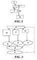
- Figure 1 depicts a diagram of the functions associated to the actuation device in an emergency situation in elevator apparatuses.
- Block (1) depicts the function of detecting an emergency situation, which function is carried out with the set of overspeed and jerk sensors with the corresponding controls associated thereto.
- block (2) is actuated, in which block the trigger function of the emergency process that is physically carried out by the control is depicted.
- Block (3) depicts the function of inhibiting the remaining braking systems, thereby preventing the motor braking system from being added to the car braking system and being able to not brake right at the floor height.
- Block (4) depicts the car braking function which is exerted by the brake plus the actuator assembly arranged in the car.
- This system is associated to the function of halting on a floor, depicted in block (5) and which is exerted by the control plus actuator plus brake assembly and which until it is not located at floor height, it does not make the elevator car stop.
- the elevator car halts on a floor, the function of opening the doors (6) is activated, which function achieves opening such doors manually or automatically and thereby evacuating the possible people who may have been traveling in the car.
- Figure 2 depicts a block diagram of the braking operation at the end of the travel, in which the position (7) in which the car is located is transmitted, this position being compared in (8) with the situation of the floors and if it coincides, the car (9) is stopped, and if it does not coincide the command is transmitted to the main control of the elevator (46) responsible for changing the position of the car by means of a power supply from the motor or by means of incorporating auxiliary batteries in order to change the position of the car, until the position of the car coincides with the position of the plan of the chosen floor, at which time the floor stop of the car (9) is performed.
- the elevator (46) responsible for changing the position of the car by means of a power supply from the motor or by means of incorporating auxiliary batteries in order to change the position of the car, until the position of the car coincides with the position of the plan of the chosen floor, at which time the floor stop of the car (9) is performed.
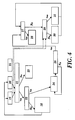
- Figure 3 depicts a block diagram of the detection device of the floor stop emergency device of the invention, with the possible actuations that can be carried out with it.
- the sensor device incorporated in the elevator is depicted in (47).
- a second possibility (11) is that regardless of the position, the car has a speed or acceleration or a surge or jerk value is produced therein that is above those stipulated as being normal, in which case the initiation of the braking (14) is proposed so that the actuator (16) is ordered to brake (17) the car and the operation triggered in the elevator being reported to the sensor device.
- the position (12) of the car is being calculated at all times, and if this position is the floor position, it proposes acting on the brake (15) so that the actuator (16) is ordered to brake (17) the car and the operation triggered in the elevator being reported to the sensor device. In the event that the position is not the floor position, the force on the brake is released for the purpose of searching for the selected floor.
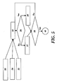
- Figure 4 depicts a block diagram of the actuation due to jerk or overspeed of the floor stop emergency device of the invention.
- the main control of the elevator in normal operation is depicted in (18), which main control orders the sensor device to take successive "n" measurements (19) (20) (25), etc..., at each instant from at least two reader elements, and successively compares the "n” measurements (21). In the event that the measurements are similar they are compared (22) if that measurement is equal to or greater than the established reference measurement. In the event of being less than the established reference safety measurement it returns a signal to the control device of the elevator (18) indicating that the operation of the elevator is correct.
- a variant of the triggering of the actuation system is shown in (23) and it would be at the point in which measurement 1 (19) or measurement 2 (20) or the successive measurements obtained do not coincide, in which case the car automatically stops wherever it is, either on a floor or between floors, for the safety of the elevator, such that the safety brake is actuated on the guides since it means there was an error in the reading.
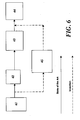
- Figure 5 depicts the block diagram of the floor stop control and (32) depicts the initiation of the rescue operation.
- This rescue operation evaluates (36) that whether or not the position, speed and acceleration are above the braking reference; if not (37), it orders reducing the braking force and if they are, it orders (38) increasing the braking force until the position, speed and acceleration coinciding with the stop are achieved in (39) and the end (40) of the rescue operation occurs; and if these values are not achieved, they are communicated to the control of the rescue operation to increase the braking force.
- the automatic autonomous activation due to an emergency situation with the car moving is shown in (33).
- the safety device evaluates and decides the need for actuation due to an emergency situation because:
- the automatic activation ordered due to an emergency situation with the car stopped between two floors is shown in (34).
- the safety device receives the command from the main control of the elevator to initiate the action by means of releasing the brake, searching for the floor position and controlling the speed and acceleration so that they do not exceed the pre-established speed and acceleration, and when it reaches a floor the brake is actuated, halting the car, opening the doors and allowing the passengers to get out.
- the manual activation is shown in (35) in which an external person or operator performs and action which triggers the floor rescue sequence due to braking.
- an external person or operator performs and action which triggers the floor rescue sequence due to braking.
- the car In the event that the car is moving, it will look for the next floor in order to stop and open the doors, whereas if the car is stopped between two floors the brake is released, looking for the next floor, and when it reaches the floor the movement of the car is stopped.
- Figure 6 schematically depicts the operation of the braking means of the elevator, thus for example the supply means of the safety of the elevator are expressed in (41), which according to the traditional process indicated in the figure with a solid line activates the safety series associated to the elevator (42) which would act by interrupting the supply of the vertical operation contactors (43) of the elevator and they would actuate the brake of the traction unit (44) upon interrupting the supply thereof and allow the braking action to be carried out as a result of the force exerted by a spring.
- the supply means of the safety of the elevator are expressed in (41), which according to the traditional process indicated in the figure with a solid line activates the safety series associated to the elevator (42) which would act by interrupting the supply of the vertical operation contactors (43) of the elevator and they would actuate the brake of the traction unit (44) upon interrupting the supply thereof and allow the braking action to be carried out as a result of the force exerted by a spring.
- the invention is focused on the incorporation of the inhibitor (45) of the brake of the traction unit, thereby preventing the actuations of the car brake from being added to that of the traction unit, which could lead to an uncontrolled braking action that could cause the apparatus to stop before reaching the desired floor level.
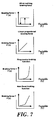
- Figure 7 schematically depicts the different braking functions that the floor stop emergency device of the invention can adopt, therefore the upper figure depicts the all-or-nothing type braking device or function of the car.
- the device acts either with maximum force or null force and the braking force is controlled by several activations and deactivations of the braking function over time, depending on input of the braking function provided from the next floor car stop control function, as shown in the mentioned Figure 7 in the upper graph.
- the second, third and fourth graphs in Figure 7 show the variable type braking device or function of the car.
- the device acts with different intermediate degrees of intensity with regard to the maximum force and the braking force is controlled by variations of the braking function over time, depending on input of the braking function provided from the next floor car stop control function.
- the braking force applied on the brake device can correspond to a mathematical function that can be linear proportion, such as that of Figure 2 in which the braking force is proportional to the input of the braking function received from the floor stop control function.
- the third graph shown in Figure 7 depicts the case of linear continuous function with progressive force, which shows the exponential curve which allows greater braking capacity for high speeds, i.e., the braking force exponentially increases with the speed of the car.
- the fourth graph of Figure 7 depicts the non-linear braking function in which there are different sections in which the graph of the braking function depending on the speed acquires different slopes depending on the sections or intervals of speed at which the car can move.
- variable (c) is determined by the function of "halting the car on a floor” and is calculated depending on the current and previous value of a variable or of a set of variables that can be the speed of the car, the position of the car, the acceleration of the car, the derivative of the acceleration of the car and of the type of braking function used.
Landscapes
- Maintenance And Inspection Apparatuses For Elevators (AREA)
- Elevator Control (AREA)
Claims (15)
- Betätigungsverfahren in einer Notfallsituation in Aufzugsanlagen, umfassend- Erfassen einer Notfallsituation (1) in dem sich bewegenden Aufzug, die das Erfassen der Position und/oder des Wegs des Wagens (19, 20, 25) innerhalb des Aufzugsschachts und das Vergleichen davon mit Bezugspositionswerten (22) umfasst, das Erfassen der Geschwindigkeit des Wagens (19, 20, 25) und Vergleichen davon mit einem Bezugsgeschwindigkeitswert (22), und Erfassen der Beschleunigung des Wagens (19, 20, 25) und Vergleichen davon mit einem Bezugsbeschleunigungswert (22);- Aktivieren der Auslösefunktion (2), wenn eine Notfallsituation erfasst wird;- Sperren des verbleibenden Bremssystems (3) des Aufzugs;- Aktivieren der Bremsfunktion (4) des Aufzugswagens, die durch die Bremseinrichtung ausgeübt wird, die ausschließlich in dem Aufzugswagen vorgesehen und angeordnet ist;- Aktivieren der Funktion des Anhaltens des Wagens auf der Höhe des Bodens (5) durch die Wirkung der Bremsfunktion (4);- manuelles oder automatisches Öffnen der Türen (6) zum Erleichtern des Aussteigens der Benutzer,- wenn eine Notfallsituation auftritt, wenn eine übermäßige Geschwindigkeit oder ein Stoss im Hinblick auf die Bezugsbeschleunigung oder Bezugsgeschwindigkeit des Wagens erfasst wird, Senden eines Eingangs an die Bremsfunktion (24), die in der Lage ist, eine Kraft zu erzeugen, die in der Lage ist, den Wagen auf eine Bezugsgeschwindigkeit (26) zu verlangsamen, die gleich oder niedriger als die Nenngeschwindigkeit des Wagens ist, dadurch gekennzeichnet, dass- sobald die Geschwindigkeit des Wagens auf die Bezugsgeschwindigkeit verlangsamt worden ist, dieser in den Bodenstopp-Steuermodus (27) eintritt, in dem der Wagen angehalten wird, sobald er an dem Boden vorbeifährt, der für sein Anhalten (28) eingerichtet ist.
- Betätigungsverfahren nach Anspruch 1, dadurch gekennzeichnet, dass die Position des Wagens der Aufzugsanlage dadurch erfasst wird, dass mehrere Messungen (19, 20, 25) erhalten werden, die miteinander (21) und mit vorab erstellten Bezugspositionswerten (22) verglichen werden.
- Betätigungsverfahren nach Anspruch 1 und 2, dadurch gekennzeichnet, dass in dem Fall, dass die gemessenen Positionswerte übereinstimmen und die vorab eingerichteten Grenzwerte überschritten werden, die Auslösevorrichtung des Fahrstuhls betätigt wird (24).
- Betätigungsverfahren nach Anspruch 1 und 2, dadurch gekennzeichnet, dass in dem Fall, dass die gemessenen Positionswerte nicht übereinstimmen, das automatische Anhalten des Wagens (23), unabhängig davon, wo sich der Wagen befindet, betätigt wird.
- Betätigungsverfahren nach Anspruch 1, dadurch gekennzeichnet, dass die Geschwindigkeit des Wagens der Aufzugsanlage dadurch erfasst wird, dass mehrere Messungen (19, 20, 25) erhalten werden, die miteinander (21) und mit einem vorab erstellten Bezugsgeschwindigkeitswert (22) verglichen werden.
- Betätigungsverfahren nach den Ansprüchen 1 und 5, dadurch gekennzeichnet, dass in dem Fall, dass die Werte der gemessenen Positionen übereinstimmen und sich nicht außerhalb der vorab erstellten Bezugspositionen befinden, und die gemessenen Geschwindigkeitswerte übereinstimmen und sich nicht oberhalb der vorab erstellten Bezugsgeschwindigkeit befinden, und die Werte der gemessenen Beschleunigungen übereinstimmen und sich nicht oberhalb der vorab erstellten Bezugsbeschleunigung befinden, der Fahrstuhl in seinem Betrieb des Anhebens oder Herunterfahrens der Last fortfährt.
- Betätigungsverfahren nach den Ansprüchen 1 und 5, dadurch gekennzeichnet, dass in dem Fall, dass die gemessenen Geschwindigkeitswerte übereinstimmen und sich oberhalb der vorab erstellten Bezugsgeschwindigkeit befinden, die Auslösevorrichtung des Aufzugs betätigt wird (24).
- Betätigungsverfahren nach Anspruch 1, dadurch gekennzeichnet, dass die Beschleunigung des Wagens der Aufzugsanlage dadurch erfasst wird, dass mehrere Messungen (19, 20, 25) erhalten werden, die miteinander (21) und mit einem vorab erstellten Bezugsbeschleunigungswert (22) verglichen werden.
- Betätigungsvorgang nach den Ansprüchen 1 und 8, dadurch gekennzeichnet, dass in dem Fall, dass die Werte der gemessenen Beschleunigungen übereinstimmen und sich oberhalb der vorab erstellten Bezugsbeschleunigung befinden, die Auslösevorrichtung des Aufzugs betätigt wird (24).
- Betätigungsverfahren nach Anspruch 1, dadurch gekennzeichnet, dass eine Aktivierung der Bremsvorrichtung des Fahrstuhls, die an dem Wagen angeordnet ist, die Verzögerung und/oder ein vollständiges Anhalten des Wagens an einem Boden (39) bewirkt.
- Betätigungsverfahren nach Anspruch 1, dadurch gekennzeichnet, dass wenn eine Notfallsituation in dem Fahrstuhl erfasst wird und bis der Wagen anhält, in Abhängigkeit von dem Ort des Wagens des Fahrstuhls, von dem Lastunterschied zwischen dem Wagen und dem Gegengewicht und von der übermäßigen Geschwindigkeit oder dem Stoss des Wagens, das System die Verzögerung berechnet, der der Wagen unterworfen werden muss, und die Bremskraft, um den Wagen auf der Höhe des nächstens Bodens anzuhalten.
- Betätigungsvorrichtung nach Anspruch 11, dadurch gekennzeichnet, dass wenn die Verzögerung, die berechnet wurde, um den Wagen an einem Boden anzuhalten, größer ist als die Kraft der Schwerkraft, wobei die Berechnung der Verzögerung und der Bremskraft im Hinblick auf den Boden ausgeführt wird, der sich unmittelbar oberhalb oder unterhalb befindet, sofern dort vorhanden.
- Betätigungsvorgang nach Anspruch 1, dadurch gekennzeichnet, dass die Betätigung der Wagenbremsvorrichtung vom Typ alles oder nichts ist.
- Betätigungsverfahren nach Anspruch 1, dadurch gekennzeichnet, dass die Bremskraft in ihrer Stärke variabel ist, abhängig vom Eingang der Bremsfunktion.
- Betätigungsverfahren nach den Ansprüchen 1 bis 14, dadurch gekennzeichnet, dass die Betätigung der Bremsvorrichtung der Traktionseinheit von dem Ziel, auf Höhe eines Bodens anzuhalten, abhängt und/oder sich davon unterscheidet.
Applications Claiming Priority (1)
| Application Number | Priority Date | Filing Date | Title |
|---|---|---|---|
| ES200702193A ES2343608B1 (es) | 2007-08-03 | 2007-08-03 | Procedimiento y dispositivo de actuacion en situacion de emergencia en aparatos elevadores. |
Publications (2)
| Publication Number | Publication Date |
|---|---|
| EP2020395A1 EP2020395A1 (de) | 2009-02-04 |
| EP2020395B1 true EP2020395B1 (de) | 2011-01-26 |
Family
ID=39967239
Family Applications (1)
| Application Number | Title | Priority Date | Filing Date |
|---|---|---|---|
| EP08380234A Not-in-force EP2020395B1 (de) | 2007-08-03 | 2008-07-30 | Verfahren und Vorrichtung im Notfallbetriebe für Aufzugslage |
Country Status (5)
| Country | Link |
|---|---|
| EP (1) | EP2020395B1 (de) |
| AT (1) | ATE496857T1 (de) |
| DE (1) | DE602008004700D1 (de) |
| ES (2) | ES2343608B1 (de) |
| PT (1) | PT2020395E (de) |
Cited By (2)
| Publication number | Priority date | Publication date | Assignee | Title |
|---|---|---|---|---|
| EP2769952A2 (de) | 2013-02-26 | 2014-08-27 | Orona, S. Coop. | Sicherheitsvorrichtung für Aufzüge und Aufzug |
| US10745239B2 (en) | 2014-11-24 | 2020-08-18 | Otis Elevator Company | Electromagnetic brake system for an elevator with variable rate of engagement |
Families Citing this family (3)
| Publication number | Priority date | Publication date | Assignee | Title |
|---|---|---|---|---|
| WO2012105986A1 (en) | 2011-02-04 | 2012-08-09 | Otis Elevator Company | Stop sequencing for braking device |
| EP3072842B1 (de) | 2015-03-23 | 2019-09-25 | Kone Corporation | Rettungssystem für einen aufzug |
| DE102016205943A1 (de) * | 2016-04-08 | 2017-10-12 | Fraunhofer-Gesellschaft zur Förderung der angewandten Forschung e.V. | Vorrichtung und Verfahren zum Fertigen von metallischen Bauteilen |
Family Cites Families (7)
| Publication number | Priority date | Publication date | Assignee | Title |
|---|---|---|---|---|
| JPS5620271B2 (de) * | 1973-10-08 | 1981-05-12 | ||
| US6170614B1 (en) | 1998-12-29 | 2001-01-09 | Otis Elevator Company | Electronic overspeed governor for elevators |
| DE50209017D1 (de) | 2001-07-04 | 2007-02-01 | Inventio Ag | Verfahren zum verhindern einer unzulässig hohen fahrgeschwindigkeit des lastaufnahmemittels eines aufzugs |
| DE60335421D1 (de) | 2003-10-07 | 2011-01-27 | Otis Elevator Co | Fernrückstellbare seillose not-stopp-vorrichtung für einen aufzug |
| US7353916B2 (en) * | 2004-06-02 | 2008-04-08 | Inventio Ag | Elevator supervision |
| FR2880009B1 (fr) * | 2004-12-27 | 2008-07-25 | Leroy Somer Moteurs | Dispositif de securite pour ascenseur |
| ATE371624T1 (de) | 2005-01-07 | 2007-09-15 | Thyssen Krupp Aufzuege Gmbh | Aufzugsanlage mit einer steuervorrichtung |
-
2007
- 2007-08-03 ES ES200702193A patent/ES2343608B1/es not_active Withdrawn - After Issue
-
2008
- 2008-07-30 DE DE602008004700T patent/DE602008004700D1/de active Active
- 2008-07-30 PT PT08380234T patent/PT2020395E/pt unknown
- 2008-07-30 AT AT08380234T patent/ATE496857T1/de not_active IP Right Cessation
- 2008-07-30 EP EP08380234A patent/EP2020395B1/de not_active Not-in-force
- 2008-07-30 ES ES08380234T patent/ES2359035T3/es active Active
Cited By (3)
| Publication number | Priority date | Publication date | Assignee | Title |
|---|---|---|---|---|
| EP2769952A2 (de) | 2013-02-26 | 2014-08-27 | Orona, S. Coop. | Sicherheitsvorrichtung für Aufzüge und Aufzug |
| US10745239B2 (en) | 2014-11-24 | 2020-08-18 | Otis Elevator Company | Electromagnetic brake system for an elevator with variable rate of engagement |
| US11897725B2 (en) | 2014-11-24 | 2024-02-13 | Otis Elevator Company | Adjustment of drop rate of elevator car with electromagnetic brake system |
Also Published As
| Publication number | Publication date |
|---|---|
| ATE496857T1 (de) | 2011-02-15 |
| DE602008004700D1 (de) | 2011-03-10 |
| PT2020395E (pt) | 2011-03-09 |
| ES2359035T3 (es) | 2011-05-17 |
| ES2343608A1 (es) | 2010-08-04 |
| ES2343608B1 (es) | 2011-06-16 |
| EP2020395A1 (de) | 2009-02-04 |
Similar Documents
| Publication | Publication Date | Title |
|---|---|---|
| EP2141108B1 (de) | Bremsvorrichtung für aufzug | |
| CN101616858B (zh) | 非预期移动调节器 | |
| CN111099469B (zh) | 电梯系统 | |
| KR101664942B1 (ko) | 엘리베이터 차체의 속력을 감소시키는 시스템 및 방법 | |
| CN108217360B (zh) | 电梯安全系统和操作电梯系统的方法 | |
| JP5526092B2 (ja) | 電子化エレベータ | |
| US20120073909A1 (en) | Elevator device | |
| CN101143670A (zh) | 变频电梯机械制动器失效时的电气保护方法和装置 | |
| CN103130065B (zh) | 电梯运行管理系统 | |
| EP2020395B1 (de) | Verfahren und Vorrichtung im Notfallbetriebe für Aufzugslage | |
| JP5419936B2 (ja) | 災害対応型エレベータシステム | |
| EP3960673B1 (de) | Aufzugsysteme | |
| EP4177206B1 (de) | Einklemmungsvermeidung in einem aufzugssystem | |
| EP3693310B1 (de) | Aktives bremsen für sofortstopps | |
| EP1701905B1 (de) | Aufzugsanordnung | |
| CN106477416B (zh) | 用于移动电梯轿厢的方法和电梯 | |
| WO2008062509A1 (en) | Elevator controller | |
| EP4324777A1 (de) | Wartungssysteme für aufzugsgruben | |
| WO2025088207A1 (en) | Elevator safety controller, elevator system, and method for causing emergency stop for elevator car | |
| KR200429753Y1 (ko) | 엘리베이터 자동 구조운전 회로 | |
| HK1133416A1 (en) | Elevator system | |
| HK1133416B (en) | Elevator system | |
| HK1139116B (en) | Elevator system with an elevator car and a braking device for stopping said elevator car in a special operating mode and a method for stopping an elevator car in a special operating mode | |
| HK1139116A1 (en) | Elevator system with an elevator car and a braking device for stopping said elevator car in a special operating mode and a method for stopping an elevator car in a special operating mode |
Legal Events
| Date | Code | Title | Description |
|---|---|---|---|
| PUAI | Public reference made under article 153(3) epc to a published international application that has entered the european phase |
Free format text: ORIGINAL CODE: 0009012 |
|
| AK | Designated contracting states |
Kind code of ref document: A1 Designated state(s): AT BE BG CH CY CZ DE DK EE ES FI FR GB GR HR HU IE IS IT LI LT LU LV MC MT NL NO PL PT RO SE SI SK TR |
|
| AX | Request for extension of the european patent |
Extension state: AL BA MK RS |
|
| 17P | Request for examination filed |
Effective date: 20090303 |
|
| AKX | Designation fees paid |
Designated state(s): AT BE BG CH CY CZ DE DK EE ES FI FR GB GR HR HU IE IS IT LI LT LU LV MC MT NL NO PL PT RO SE SI SK TR |
|
| GRAP | Despatch of communication of intention to grant a patent |
Free format text: ORIGINAL CODE: EPIDOSNIGR1 |
|
| GRAS | Grant fee paid |
Free format text: ORIGINAL CODE: EPIDOSNIGR3 |
|
| GRAA | (expected) grant |
Free format text: ORIGINAL CODE: 0009210 |
|
| RIN1 | Information on inventor provided before grant (corrected) |
Inventor name: MARITXALAR, ALBERTO Inventor name: REDONDO, JOSE ANTONIO Inventor name: PEREZ, ANTONIO |
|
| AK | Designated contracting states |
Kind code of ref document: B1 Designated state(s): AT BE BG CH CY CZ DE DK EE ES FI FR GB GR HR HU IE IS IT LI LT LU LV MC MT NL NO PL PT RO SE SI SK TR |
|
| REG | Reference to a national code |
Ref country code: GB Ref legal event code: FG4D |
|
| REG | Reference to a national code |
Ref country code: CH Ref legal event code: EP |
|
| REG | Reference to a national code |
Ref country code: IE Ref legal event code: FG4D |
|
| REG | Reference to a national code |
Ref country code: PT Ref legal event code: SC4A Free format text: AVAILABILITY OF NATIONAL TRANSLATION Effective date: 20110301 |
|
| REF | Corresponds to: |
Ref document number: 602008004700 Country of ref document: DE Date of ref document: 20110310 Kind code of ref document: P |
|
| REG | Reference to a national code |
Ref country code: DE Ref legal event code: R096 Ref document number: 602008004700 Country of ref document: DE Effective date: 20110310 |
|
| REG | Reference to a national code |
Ref country code: ES Ref legal event code: FG2A Ref document number: 2359035 Country of ref document: ES Kind code of ref document: T3 Effective date: 20110517 |
|
| REG | Reference to a national code |
Ref country code: NL Ref legal event code: VDEP Effective date: 20110126 |
|
| LTIE | Lt: invalidation of european patent or patent extension |
Effective date: 20110126 |
|
| PG25 | Lapsed in a contracting state [announced via postgrant information from national office to epo] |
Ref country code: IS Free format text: LAPSE BECAUSE OF FAILURE TO SUBMIT A TRANSLATION OF THE DESCRIPTION OR TO PAY THE FEE WITHIN THE PRESCRIBED TIME-LIMIT Effective date: 20110526 Ref country code: HR Free format text: LAPSE BECAUSE OF FAILURE TO SUBMIT A TRANSLATION OF THE DESCRIPTION OR TO PAY THE FEE WITHIN THE PRESCRIBED TIME-LIMIT Effective date: 20110126 Ref country code: GR Free format text: LAPSE BECAUSE OF FAILURE TO SUBMIT A TRANSLATION OF THE DESCRIPTION OR TO PAY THE FEE WITHIN THE PRESCRIBED TIME-LIMIT Effective date: 20110427 Ref country code: SE Free format text: LAPSE BECAUSE OF FAILURE TO SUBMIT A TRANSLATION OF THE DESCRIPTION OR TO PAY THE FEE WITHIN THE PRESCRIBED TIME-LIMIT Effective date: 20110126 Ref country code: NO Free format text: LAPSE BECAUSE OF FAILURE TO SUBMIT A TRANSLATION OF THE DESCRIPTION OR TO PAY THE FEE WITHIN THE PRESCRIBED TIME-LIMIT Effective date: 20110426 Ref country code: LT Free format text: LAPSE BECAUSE OF FAILURE TO SUBMIT A TRANSLATION OF THE DESCRIPTION OR TO PAY THE FEE WITHIN THE PRESCRIBED TIME-LIMIT Effective date: 20110126 Ref country code: LV Free format text: LAPSE BECAUSE OF FAILURE TO SUBMIT A TRANSLATION OF THE DESCRIPTION OR TO PAY THE FEE WITHIN THE PRESCRIBED TIME-LIMIT Effective date: 20110126 |
|
| PG25 | Lapsed in a contracting state [announced via postgrant information from national office to epo] |
Ref country code: NL Free format text: LAPSE BECAUSE OF FAILURE TO SUBMIT A TRANSLATION OF THE DESCRIPTION OR TO PAY THE FEE WITHIN THE PRESCRIBED TIME-LIMIT Effective date: 20110126 Ref country code: FI Free format text: LAPSE BECAUSE OF FAILURE TO SUBMIT A TRANSLATION OF THE DESCRIPTION OR TO PAY THE FEE WITHIN THE PRESCRIBED TIME-LIMIT Effective date: 20110126 Ref country code: BE Free format text: LAPSE BECAUSE OF FAILURE TO SUBMIT A TRANSLATION OF THE DESCRIPTION OR TO PAY THE FEE WITHIN THE PRESCRIBED TIME-LIMIT Effective date: 20110126 Ref country code: CY Free format text: LAPSE BECAUSE OF FAILURE TO SUBMIT A TRANSLATION OF THE DESCRIPTION OR TO PAY THE FEE WITHIN THE PRESCRIBED TIME-LIMIT Effective date: 20110126 Ref country code: SI Free format text: LAPSE BECAUSE OF FAILURE TO SUBMIT A TRANSLATION OF THE DESCRIPTION OR TO PAY THE FEE WITHIN THE PRESCRIBED TIME-LIMIT Effective date: 20110126 Ref country code: BG Free format text: LAPSE BECAUSE OF FAILURE TO SUBMIT A TRANSLATION OF THE DESCRIPTION OR TO PAY THE FEE WITHIN THE PRESCRIBED TIME-LIMIT Effective date: 20110426 Ref country code: PL Free format text: LAPSE BECAUSE OF FAILURE TO SUBMIT A TRANSLATION OF THE DESCRIPTION OR TO PAY THE FEE WITHIN THE PRESCRIBED TIME-LIMIT Effective date: 20110126 Ref country code: AT Free format text: LAPSE BECAUSE OF FAILURE TO SUBMIT A TRANSLATION OF THE DESCRIPTION OR TO PAY THE FEE WITHIN THE PRESCRIBED TIME-LIMIT Effective date: 20110126 |
|
| PG25 | Lapsed in a contracting state [announced via postgrant information from national office to epo] |
Ref country code: EE Free format text: LAPSE BECAUSE OF FAILURE TO SUBMIT A TRANSLATION OF THE DESCRIPTION OR TO PAY THE FEE WITHIN THE PRESCRIBED TIME-LIMIT Effective date: 20110126 Ref country code: DK Free format text: LAPSE BECAUSE OF FAILURE TO SUBMIT A TRANSLATION OF THE DESCRIPTION OR TO PAY THE FEE WITHIN THE PRESCRIBED TIME-LIMIT Effective date: 20110126 |
|
| PG25 | Lapsed in a contracting state [announced via postgrant information from national office to epo] |
Ref country code: SK Free format text: LAPSE BECAUSE OF FAILURE TO SUBMIT A TRANSLATION OF THE DESCRIPTION OR TO PAY THE FEE WITHIN THE PRESCRIBED TIME-LIMIT Effective date: 20110126 Ref country code: RO Free format text: LAPSE BECAUSE OF FAILURE TO SUBMIT A TRANSLATION OF THE DESCRIPTION OR TO PAY THE FEE WITHIN THE PRESCRIBED TIME-LIMIT Effective date: 20110126 Ref country code: CZ Free format text: LAPSE BECAUSE OF FAILURE TO SUBMIT A TRANSLATION OF THE DESCRIPTION OR TO PAY THE FEE WITHIN THE PRESCRIBED TIME-LIMIT Effective date: 20110126 |
|
| PLBE | No opposition filed within time limit |
Free format text: ORIGINAL CODE: 0009261 |
|
| STAA | Information on the status of an ep patent application or granted ep patent |
Free format text: STATUS: NO OPPOSITION FILED WITHIN TIME LIMIT |
|
| PG25 | Lapsed in a contracting state [announced via postgrant information from national office to epo] |
Ref country code: MT Free format text: LAPSE BECAUSE OF FAILURE TO SUBMIT A TRANSLATION OF THE DESCRIPTION OR TO PAY THE FEE WITHIN THE PRESCRIBED TIME-LIMIT Effective date: 20110126 |
|
| 26N | No opposition filed |
Effective date: 20111027 |
|
| REG | Reference to a national code |
Ref country code: DE Ref legal event code: R097 Ref document number: 602008004700 Country of ref document: DE Effective date: 20111027 |
|
| PG25 | Lapsed in a contracting state [announced via postgrant information from national office to epo] |
Ref country code: MC Free format text: LAPSE BECAUSE OF NON-PAYMENT OF DUE FEES Effective date: 20110731 |
|
| REG | Reference to a national code |
Ref country code: CH Ref legal event code: PL |
|
| PG25 | Lapsed in a contracting state [announced via postgrant information from national office to epo] |
Ref country code: CH Free format text: LAPSE BECAUSE OF NON-PAYMENT OF DUE FEES Effective date: 20120731 Ref country code: LI Free format text: LAPSE BECAUSE OF NON-PAYMENT OF DUE FEES Effective date: 20120731 |
|
| PG25 | Lapsed in a contracting state [announced via postgrant information from national office to epo] |
Ref country code: LU Free format text: LAPSE BECAUSE OF NON-PAYMENT OF DUE FEES Effective date: 20110730 |
|
| PG25 | Lapsed in a contracting state [announced via postgrant information from national office to epo] |
Ref country code: TR Free format text: LAPSE BECAUSE OF FAILURE TO SUBMIT A TRANSLATION OF THE DESCRIPTION OR TO PAY THE FEE WITHIN THE PRESCRIBED TIME-LIMIT Effective date: 20110126 |
|
| PG25 | Lapsed in a contracting state [announced via postgrant information from national office to epo] |
Ref country code: HU Free format text: LAPSE BECAUSE OF FAILURE TO SUBMIT A TRANSLATION OF THE DESCRIPTION OR TO PAY THE FEE WITHIN THE PRESCRIBED TIME-LIMIT Effective date: 20110126 |
|
| REG | Reference to a national code |
Ref country code: FR Ref legal event code: PLFP Year of fee payment: 9 |
|
| REG | Reference to a national code |
Ref country code: FR Ref legal event code: PLFP Year of fee payment: 10 |
|
| REG | Reference to a national code |
Ref country code: FR Ref legal event code: PLFP Year of fee payment: 11 |
|
| PGFP | Annual fee paid to national office [announced via postgrant information from national office to epo] |
Ref country code: PT Payment date: 20180724 Year of fee payment: 11 |
|
| PG25 | Lapsed in a contracting state [announced via postgrant information from national office to epo] |
Ref country code: PT Free format text: LAPSE BECAUSE OF NON-PAYMENT OF DUE FEES Effective date: 20200130 |
|
| PG25 | Lapsed in a contracting state [announced via postgrant information from national office to epo] |
Ref country code: IE Free format text: LAPSE BECAUSE OF NON-PAYMENT OF DUE FEES Effective date: 20190730 |
|
| PGFP | Annual fee paid to national office [announced via postgrant information from national office to epo] |
Ref country code: IT Payment date: 20220726 Year of fee payment: 15 Ref country code: GB Payment date: 20220728 Year of fee payment: 15 Ref country code: ES Payment date: 20220804 Year of fee payment: 15 Ref country code: DE Payment date: 20220630 Year of fee payment: 15 |
|
| PGFP | Annual fee paid to national office [announced via postgrant information from national office to epo] |
Ref country code: FR Payment date: 20220728 Year of fee payment: 15 |
|
| P01 | Opt-out of the competence of the unified patent court (upc) registered |
Effective date: 20230604 |
|
| REG | Reference to a national code |
Ref country code: DE Ref legal event code: R119 Ref document number: 602008004700 Country of ref document: DE |
|
| GBPC | Gb: european patent ceased through non-payment of renewal fee |
Effective date: 20230730 |
|
| PG25 | Lapsed in a contracting state [announced via postgrant information from national office to epo] |
Ref country code: DE Free format text: LAPSE BECAUSE OF NON-PAYMENT OF DUE FEES Effective date: 20240201 Ref country code: GB Free format text: LAPSE BECAUSE OF NON-PAYMENT OF DUE FEES Effective date: 20230730 |
|
| PG25 | Lapsed in a contracting state [announced via postgrant information from national office to epo] |
Ref country code: FR Free format text: LAPSE BECAUSE OF NON-PAYMENT OF DUE FEES Effective date: 20230731 |
|
| PG25 | Lapsed in a contracting state [announced via postgrant information from national office to epo] |
Ref country code: IT Free format text: LAPSE BECAUSE OF NON-PAYMENT OF DUE FEES Effective date: 20230730 |
|
| REG | Reference to a national code |
Ref country code: ES Ref legal event code: FD2A Effective date: 20240902 |
|
| PG25 | Lapsed in a contracting state [announced via postgrant information from national office to epo] |
Ref country code: ES Free format text: LAPSE BECAUSE OF NON-PAYMENT OF DUE FEES Effective date: 20230731 |
|
| PG25 | Lapsed in a contracting state [announced via postgrant information from national office to epo] |
Ref country code: ES Free format text: LAPSE BECAUSE OF NON-PAYMENT OF DUE FEES Effective date: 20230731 |