EP2020434B1 - Reaktor zur anaeroben Erzeugung von Biogas - Google Patents
Reaktor zur anaeroben Erzeugung von Biogas Download PDFInfo
- Publication number
- EP2020434B1 EP2020434B1 EP07425509A EP07425509A EP2020434B1 EP 2020434 B1 EP2020434 B1 EP 2020434B1 EP 07425509 A EP07425509 A EP 07425509A EP 07425509 A EP07425509 A EP 07425509A EP 2020434 B1 EP2020434 B1 EP 2020434B1
- Authority
- EP
- European Patent Office
- Prior art keywords
- fraction
- chamber
- pipe
- axis
- biogas
- Prior art date
- Legal status (The legal status is an assumption and is not a legal conclusion. Google has not performed a legal analysis and makes no representation as to the accuracy of the status listed.)
- Not-in-force
Links
- 238000004519 manufacturing process Methods 0.000 title claims description 6
- 239000002699 waste material Substances 0.000 claims description 49
- 239000000203 mixture Substances 0.000 claims description 42
- 238000003860 storage Methods 0.000 claims description 7
- 238000005842 biochemical reaction Methods 0.000 claims description 6
- 239000000463 material Substances 0.000 claims description 6
- 238000006243 chemical reaction Methods 0.000 claims description 5
- 230000001131 transforming effect Effects 0.000 claims 1
- XLYOFNOQVPJJNP-UHFFFAOYSA-N water Substances O XLYOFNOQVPJJNP-UHFFFAOYSA-N 0.000 description 26
- 244000005700 microbiome Species 0.000 description 10
- 238000002203 pretreatment Methods 0.000 description 8
- 238000003756 stirring Methods 0.000 description 6
- 230000005484 gravity Effects 0.000 description 4
- 239000012535 impurity Substances 0.000 description 3
- 239000002244 precipitate Substances 0.000 description 3
- 238000001556 precipitation Methods 0.000 description 3
- 238000007873 sieving Methods 0.000 description 3
- CURLTUGMZLYLDI-UHFFFAOYSA-N Carbon dioxide Chemical compound O=C=O CURLTUGMZLYLDI-UHFFFAOYSA-N 0.000 description 2
- 230000015572 biosynthetic process Effects 0.000 description 2
- 238000009264 composting Methods 0.000 description 2
- 238000006073 displacement reaction Methods 0.000 description 2
- VNWKTOKETHGBQD-UHFFFAOYSA-N methane Chemical compound C VNWKTOKETHGBQD-UHFFFAOYSA-N 0.000 description 2
- 229910002092 carbon dioxide Inorganic materials 0.000 description 1
- 239000001569 carbon dioxide Substances 0.000 description 1
- 238000010276 construction Methods 0.000 description 1
- 230000003247 decreasing effect Effects 0.000 description 1
- 238000010586 diagram Methods 0.000 description 1
- 230000029087 digestion Effects 0.000 description 1
- 230000003028 elevating effect Effects 0.000 description 1
- 238000000034 method Methods 0.000 description 1
- 239000002245 particle Substances 0.000 description 1
- 239000007787 solid Substances 0.000 description 1
- 238000007711 solidification Methods 0.000 description 1
- 230000008023 solidification Effects 0.000 description 1
- 238000011282 treatment Methods 0.000 description 1
Images



Classifications
-
- C—CHEMISTRY; METALLURGY
- C12—BIOCHEMISTRY; BEER; SPIRITS; WINE; VINEGAR; MICROBIOLOGY; ENZYMOLOGY; MUTATION OR GENETIC ENGINEERING
- C12M—APPARATUS FOR ENZYMOLOGY OR MICROBIOLOGY; APPARATUS FOR CULTURING MICROORGANISMS FOR PRODUCING BIOMASS, FOR GROWING CELLS OR FOR OBTAINING FERMENTATION OR METABOLIC PRODUCTS, i.e. BIOREACTORS OR FERMENTERS
- C12M21/00—Bioreactors or fermenters specially adapted for specific uses
- C12M21/04—Bioreactors or fermenters specially adapted for specific uses for producing gas, e.g. biogas
-
- B—PERFORMING OPERATIONS; TRANSPORTING
- B01—PHYSICAL OR CHEMICAL PROCESSES OR APPARATUS IN GENERAL
- B01F—MIXING, e.g. DISSOLVING, EMULSIFYING OR DISPERSING
- B01F25/00—Flow mixers; Mixers for falling materials, e.g. solid particles
- B01F25/50—Circulation mixers, e.g. wherein at least part of the mixture is discharged from and reintroduced into a receptacle
- B01F25/52—Circulation mixers, e.g. wherein at least part of the mixture is discharged from and reintroduced into a receptacle with a rotary stirrer in the recirculation tube
-
- B—PERFORMING OPERATIONS; TRANSPORTING
- B01—PHYSICAL OR CHEMICAL PROCESSES OR APPARATUS IN GENERAL
- B01F—MIXING, e.g. DISSOLVING, EMULSIFYING OR DISPERSING
- B01F27/00—Mixers with rotary stirring devices in fixed receptacles; Kneaders
- B01F27/05—Stirrers
- B01F27/11—Stirrers characterised by the configuration of the stirrers
- B01F27/19—Stirrers with two or more mixing elements mounted in sequence on the same axis
- B01F27/191—Stirrers with two or more mixing elements mounted in sequence on the same axis with similar elements
-
- B—PERFORMING OPERATIONS; TRANSPORTING
- B01—PHYSICAL OR CHEMICAL PROCESSES OR APPARATUS IN GENERAL
- B01F—MIXING, e.g. DISSOLVING, EMULSIFYING OR DISPERSING
- B01F27/00—Mixers with rotary stirring devices in fixed receptacles; Kneaders
- B01F27/80—Mixers with rotary stirring devices in fixed receptacles; Kneaders with stirrers rotating about a substantially vertical axis
- B01F27/91—Mixers with rotary stirring devices in fixed receptacles; Kneaders with stirrers rotating about a substantially vertical axis with propellers
-
- C—CHEMISTRY; METALLURGY
- C12—BIOCHEMISTRY; BEER; SPIRITS; WINE; VINEGAR; MICROBIOLOGY; ENZYMOLOGY; MUTATION OR GENETIC ENGINEERING
- C12M—APPARATUS FOR ENZYMOLOGY OR MICROBIOLOGY; APPARATUS FOR CULTURING MICROORGANISMS FOR PRODUCING BIOMASS, FOR GROWING CELLS OR FOR OBTAINING FERMENTATION OR METABOLIC PRODUCTS, i.e. BIOREACTORS OR FERMENTERS
- C12M29/00—Means for introduction, extraction or recirculation of materials, e.g. pumps
- C12M29/24—Recirculation of gas
-
- C—CHEMISTRY; METALLURGY
- C12—BIOCHEMISTRY; BEER; SPIRITS; WINE; VINEGAR; MICROBIOLOGY; ENZYMOLOGY; MUTATION OR GENETIC ENGINEERING
- C12M—APPARATUS FOR ENZYMOLOGY OR MICROBIOLOGY; APPARATUS FOR CULTURING MICROORGANISMS FOR PRODUCING BIOMASS, FOR GROWING CELLS OR FOR OBTAINING FERMENTATION OR METABOLIC PRODUCTS, i.e. BIOREACTORS OR FERMENTERS
- C12M45/00—Means for pre-treatment of biological substances
- C12M45/02—Means for pre-treatment of biological substances by mechanical forces; Stirring; Trituration; Comminuting
-
- C—CHEMISTRY; METALLURGY
- C12—BIOCHEMISTRY; BEER; SPIRITS; WINE; VINEGAR; MICROBIOLOGY; ENZYMOLOGY; MUTATION OR GENETIC ENGINEERING
- C12M—APPARATUS FOR ENZYMOLOGY OR MICROBIOLOGY; APPARATUS FOR CULTURING MICROORGANISMS FOR PRODUCING BIOMASS, FOR GROWING CELLS OR FOR OBTAINING FERMENTATION OR METABOLIC PRODUCTS, i.e. BIOREACTORS OR FERMENTERS
- C12M45/00—Means for pre-treatment of biological substances
- C12M45/04—Phase separators; Separation of non fermentable material; Fractionation
-
- C—CHEMISTRY; METALLURGY
- C12—BIOCHEMISTRY; BEER; SPIRITS; WINE; VINEGAR; MICROBIOLOGY; ENZYMOLOGY; MUTATION OR GENETIC ENGINEERING
- C12M—APPARATUS FOR ENZYMOLOGY OR MICROBIOLOGY; APPARATUS FOR CULTURING MICROORGANISMS FOR PRODUCING BIOMASS, FOR GROWING CELLS OR FOR OBTAINING FERMENTATION OR METABOLIC PRODUCTS, i.e. BIOREACTORS OR FERMENTERS
- C12M45/00—Means for pre-treatment of biological substances
- C12M45/20—Heating; Cooling
-
- Y—GENERAL TAGGING OF NEW TECHNOLOGICAL DEVELOPMENTS; GENERAL TAGGING OF CROSS-SECTIONAL TECHNOLOGIES SPANNING OVER SEVERAL SECTIONS OF THE IPC; TECHNICAL SUBJECTS COVERED BY FORMER USPC CROSS-REFERENCE ART COLLECTIONS [XRACs] AND DIGESTS
- Y02—TECHNOLOGIES OR APPLICATIONS FOR MITIGATION OR ADAPTATION AGAINST CLIMATE CHANGE
- Y02E—REDUCTION OF GREENHOUSE GAS [GHG] EMISSIONS, RELATED TO ENERGY GENERATION, TRANSMISSION OR DISTRIBUTION
- Y02E50/00—Technologies for the production of fuel of non-fossil origin
- Y02E50/30—Fuel from waste, e.g. synthetic alcohol or diesel
Definitions
- the present invention relates to a reactor for the anaerobic production of biogas from pre-treated wet waste.
- biogas production plants comprising a feeding station of wet waste in bags, a pre-treatment unit of the aforesaid wet waste, and a reactor, in which the pre-treated wet waste biochemically reacts with appropriate micro-organisms.
- Such biochemical reaction generates biogas useable as source of energy and a reject, known as digestate, meant to be conveyed to a composting plant.
- the pre-treatment unit sequentially performs on the wet waste a first crushing adapted to break the bags, a sieving adapted to eliminate predetermined impurities, and a second crushing contemplated to take the wet waste itself to a sufficiently small dimension to be made suitable for the subsequent biochemical reaction.
- Bio-digestion plants further comprise a tank interposed between the pre-treatment unit and the reactor along the wet waste feed line.
- such tank is adapted to dilute in water and heat up the wet waste coming from the pre-treatment unit, concurrently separating a fraction of non-biodegradable discards from the wet waste itself.
- the reactor essentially comprises a first chamber receiving the water and wet waste mixture from the tank, and in which the inert materials are eliminated from the aforesaid mixture by precipitation; and a second chamber, in which the aforesaid mixture is made to react, under anaerobic conditions, with micro-organisms generating the biogas and the digestate.
- the second chamber surrounds the first chamber and receives the aforesaid mixture, by overflowing, from the first chamber itself.
- the biogas predominantly consists of methane and for the remaining part of carbon dioxide and other components, and it is accumulated in a storage gasometer, from where it is subsequently conveyed to a use station, e.g. a co-generation plant.
- a first fraction of the digestate is accumulated, by gravity, in a bottom portion of the second chamber, from where it is subsequently conveyed, after having been dehydrated, to a composting plant.
- a second fraction of the digestate lighter than the aforesaid first fraction, floats on the free surface of the wet waste and water mixture which is reacting with the micro-organisms in the second chamber.
- Such second fraction is manually removed, in a known manner, i.e. by creating a manhole for an operator in a region of the second chamber adjacent to the aforesaid free surface and employing an appropriate manual tool, with which the operator manually removes the second fraction and collects it in a discharge tank.
- BE-A-897693 discloses a reactor according to the preamble of claim 1.
- US-A-3954619 discloses a reactor comprising a movable element to convey the floating solids towards an outlet.
- the aforesaid object is reached by the present invention in that it relates to a reactor for the anaerobic production of biogas from pre-treated wet waste as defined in claim 1.
- numeral 1 indicates a pre-treated wet waste anaerobic bio-digestion plant.
- the plant 1 essentially comprises:
- the reactor 4 discontinuously processes fair volumes of the aforesaid mixture, i.e. receives in input a volume of mixture, and discharges such volume, once the mixture has completed the reaction with the micro-organisms.
- Such light fraction of the digestate essentially consists of organic component particles.
- the wet waste undergoes a pre-treatment essentially consisting of a first, course crushing aimed at tearing the bags, of a sieving adapted to deprive the wet waste from predetermined impurities and of a second crushing adapted to make the wet waste of sufficiently small dimensions to be able to react with the micro-organisms in the reactor.
- the tank 3 is adapted to maintain the wet waste thus pre-treated in a state of stirring (in a manner only diagrammatically shown in figure 1 ) so as to separate a fraction consisting of non-biodegradable discards from the wet waste and water mixture.
- Such wet waste and water mixture after having left the tank 3, is pumped (in a manner not shown) into the reactor 4.
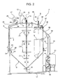
- the reactor 4 ( figures 1 , 2 and 3 ) essentially comprises:
- the reactor 4 extends along an axis A vertically arranged in use and is delimited by a main cylindrical wall 8 of axis A, by a top wall 9 and by a truncated cone bottom wall 10 having decreasing radial dimension proceeding from the wall 8 opposing the wall 9.
- the walls 9, 10 are arranged on opposite sides of the wall 8.
- the wall 8 laterally delimits the chamber 6 with respect to axis A, and faces away from axis A, while the walls 9, 10 are incident and transversal to axis A.
- the pre-chamber 5 protrudes overhanging in the reactor 4 from a segment 11 of the wall 8 and from a segment, contiguous to the segment 11, of the wall 10.
- the pre-chamber 5 extends in the reactor 4 in an eccentric position with respect to axis A and on one side of axis A itself.
- the pre-chamber 5 essentially comprises a closed bottom meant to collect the inert materials separated by precipitation, and a side wall extending from the segment 11 of the wall 8.
- the segment 11 of the wall 8 is crossed by the inlet mouth 7, which is fluidically connected to the tank 3 to allow the water and wet waste mixture to reach the pre-chamber 5 itself.
- the pre-chamber 5 is open in the upper part and on the side opposite to the closed bottom to allow the wet waste and water mixture to overflow into the chamber 6.
- the chamber 6 occupies the volume of the reactor 4 not occupied by the pre-chamber 5, is selectively connectable to a biogas storage gasometer 12 (only diagrammatically indicated in figures 1 and 2 ) by means of an outlet mouth 13 obtained in the wall 9, and is selectively connectable to a treatment plant 14 (only diagrammatically indicated in figure 1 ) of the heavy fraction of the digestate, by means of an outlet mouth 15 obtained at an end of the wall 10, opposite to the wall 8.
- a conveying pipe 16 of the biogas is interposed between the outlet mouth 13 and the gasometer 12, and a conveying pipe 17 of the heavy digestate fraction is interposed between the outlet mouth 15 and the plant 14.
- the biochemical reaction occurs at a temperature of approximately 50 degrees centigrade and the wet waste and water mixture remains in the chamber 6 itself for at least fourteen days.
- the reactor 4 comprises a stirring system interacting with the wet waste and water mixture to maintain the mixture itself in a state of constant motion preventing the partial solidification thereof, and to promote the progress of the reaction with the micro-organisms.
- the stirring system comprises a shaft 20 accommodated in the chamber 6, turnable about axis A, and provided with a plurality of disc-shaped appendixes 21, four in the case in point, radially protruding from the shaft 20 itself and interacting with the wet waste and water mixture.
- the shaft 20 is actuated by a motor 19 (shown only in figure 2 ), extends overhanging from the wall 9 and presents a free end opposite to the wall 9 itself, accommodated in the chamber 6 and surrounded by the wall 10.
- the stirring system comprises supplying means of a plurality of biogas jets in the chamber 6.
- the supplying means are fed with the biogas produced in the chamber 6, pass through the wall 8 and are provided with a plurality of supplying mouths 23, five in the case in point (only one of which is shown in figure 2 ), of corresponding biogas jets in the chamber 6.
- the mouths 23 are arranged in corresponding portions adjacent to the wall 8 to maintain corresponding regions of the mixture spaced from the shaft 20 and adjacent to the wall 8 itself in a continuous state of stirring.
- the supplying means comprise:
- each pipe 26 is fluidically interposed between a corresponding deviation 27 of the pipe 16 and the corresponding nozzle 22.
- a compressor 29 (only diagrammatically shown in figures 2 and 3 ) adapted to increase the pressure of the biogas fed to pipes 26 and supplied into chamber 6.
- the pipes 26 are secured to the external surfaces of the walls 8 and 9.
- valves 28 (only one of which is shown in figures 1 and 2 ) electronically controlled by a control unit (not shown in the accompanying figures).
- valves 28 are controlled so that only one of them is opened, while the other valves 28 remain closed.
- the opening sequence of the valves 28 depends on the viscosity of the water and wet waste mixture and is such to promote a displacement action of the aforesaid mixture towards the wall 9.
- valves 28 By controlling the valves 28 so that the biogas flows only along one pipe 26 at a time, and thus so that only one mouth 23 at a time supplies biogas into chamber 6, the formation of a circular crown of solidified wet waste on the internal surface of the chamber 6 is also prevented.
- Each nozzle 22 is arranged inside the chamber 6, and comprises a first end receiving the biogas from the corresponding pipe 26, and a second free end, opposite to the first end, defining the outlet mouth 23 of the corresponding biogas jet.
- each nozzle 22 comprises a first segment 24 extending in a radial direction with respect to axis A and provided with the corresponding first end, and a second segment 25 extending from the segment 24 parallelly to axis A and towards the outlet mouth 15.
- the segment 25, moreover, defines the mouth 23.
- biogas jets exiting from the mouths 23 are thus directed parallelly to axis A, towards the wall 10 and in a position adjacent to the wall 8. In such manner, such jets maintain the wet waste and water mixture in motion in corresponding regions of the chamber 6 adjacent to the wall 8 and away from the shaft 20.
- each mouth 23 lays on an inclined plane with respect to axis A and is shaped so as to move closer to the wall 9, proceeding from the corresponding pipe 26 towards the shaft 20.
- Such shape of the mouths 23 slows down the speed of the biogas passing through the mouths 23 themselves and contrasts the occlusion of the mouths 23 by the reacting water and wet waste mixture.
- the reactor 4 comprises a tank 31 fluidically connected to the chamber 6 and crossed by the pipe 17.
- the tank 31, being fluidically connected to the chamber 6, is normally full of biogas.
- the reactor 4 comprises a removal device 35 of the light fraction of the digestate accommodated in the chamber 6 and comprising, in turn:
- the device 35 ( figure 4 ) is arranged in an eccentric position with respect to axis A and higher than the appendix 21 arranged in the highest position and thus, closest to the wall 9. Furthermore, the device 35 is essentially arranged at the same distance as the pre-chamber 5 from the axis A.
- the element 36 is fixed to the reactor 4 and comprises a basin 37 open towards the wall 9 and fluidically connected, on the side opposite to the wall 9, to the discharge tank 60.
- the element 36 comprises a wall defining a chute 39 adjacent to the element 38, inclined with respect to axis A and immersed in the wet waste and water mixture immediately underneath the free surface 61.
- the chute 39 presents a first end edge contiguous to the basin 37 and a second free end edge, opposite to the first end.
- first edge of the chute 39 extends for a shorter length than the second edge of the chute 39 itself.
- the chute 39 thus defines a feed surface for the light fraction of the digestate conveyed from the element 38 itself towards the basin 37 converging towards the basin 37 itself.
- the first edge of the chute 39 is arranged in a higher position than the second edge of the chute 39 itself so as to promote the return of the water dragged by the element 38 along with the light fraction of the reject back into the chamber 6.
- the basin 37 further presents a pipe 50 fluidically connected to the discharge tank 60 on the opposite side of the wall 9.
- the element 38 is rotational about an axis B, parallel to axis A, to carry away such light fraction and guide it along the chute 39 and into the basin 37.
- the element 38 specifically comprises a motor (not shown), a shaft 40 operatively connected to the motor itself to be rotationally fed about axis B, and a crossbar 41 integral with the shaft 40 and provided, on both sides, with a plurality of strips 42 of elastically deformable material, specifically rubber, adapted to be immersed ( figures 1 and 2 ) immediately underneath the free surface 61 and to interact with the light floating fraction to guide it along the chute 39 and towards the basin 37.
- a motor not shown
- a shaft 40 operatively connected to the motor itself to be rotationally fed about axis B
- a crossbar 41 integral with the shaft 40 and provided, on both sides, with a plurality of strips 42 of elastically deformable material, specifically rubber, adapted to be immersed ( figures 1 and 2 ) immediately underneath the free surface 61 and to interact with the light floating fraction to guide it along the chute 39 and towards the basin 37.
- the crossbar 41 lays on a plane parallel to axis B and vertically arranged in use, while the strips 42 are elongated orthogonally to axis B.
- the crossbar 41 is delimited in the lower part by an edge opposite to the shaft 40 and arranged at the same height as the second edge of the chute 39.
- the pipe 50 presents a first end connected to the basin 37 and a second end opposite to the first end defined by a branch 49.
- a tube 52 ending in the tank 31 and a tube 51 ending in the discharge tank 60 of the light fraction of the digestate originate at such branch 49.
- the tube 51 presents a pair of reciprocally spaced valves 44, 45 adapted to discharge the light fraction of the digestate without generating leakages of biogas.
- valve 44 is interposed between the valve 45 and the branch 49.
- the tube 51 is normally full of biogas and of the light fraction of the digestate. Specifically, the light fraction of the digestate is heavier than the biogas and is arranged, by gravity, at the end adjacent to the valve 44 of the portion of the tube 51 interposed between the branch 49 and the valve 44.
- the valve 44 is, moreover, displaceable between an opened position in which it allows the passage of the light fraction of the digestate into the portion of the tube 51 interposed between the valves 44, 45, and a second closed position in which it prevents the biogas contained in the tube 51 from reaching the portion of the tube 51 interposed between the valves 44, 45.
- the valve 45 is arranged in a closed position when the valve 44 is arranged in the opened position so as to trap the light fraction of the digestate in the portion of the tube 51 comprised between the valves 44, 45.
- valve 45 is arranged in the opened position, when the valve 44 is arranged in the closed position to allow the light fraction of the digestate previously trapped between the valves 44, 45 to reach the discharge tank 60.
- the unit 2 performs a plurality of pre-treatments on the wet waste fed in bags. More specifically, such pre-treatments comprise a first crushing aimed at tearing the bags, a sieving adapted to deprive the wet waste of predetermined impurities, and a second crushing contemplated to make the wet waste of sufficiently small dimensions to be able to react with the micro-organisms in the reactor 4.
- the wet waste exiting from the unit 2 reach the tank 3, where they are diluted and heated up to approximately sixty-five degrees centigrade and, later, they advance towards the inlet 7 of the pre-chamber 5.
- the inert materials are separated from the mixture and precipitate onto the closed bottom of the pre-chamber 5 itself.
- the wet waste and water mixture overflows from the pre-chamber 5 into the chamber 6, where it reacts, at a temperature of approximately 50-55 degrees centigrade and for a time of at least fourteen days, with the micro-organisms present in the chamber 6 itself generating biogas and digestate.
- the biogas moves up towards the wall 9, while the heavy fraction of the digestate precipitates by gravity inside the chamber 6 and accumulates on the wall 10.
- the light fraction of the biogas floats on a free surface 61 of the wet waste and water mixture.
- the outlet mouth 13 is opened and the biogas reaches the gasometer 12 by means of the pipe 16.
- the biogas is stored in the gasometer 12 and subsequently made available to a co-generation plant.
- the rotation of the shaft 20 maintains the region of the wet waste and water mixture adjacent to axis A in a constant state of stirring.
- part of the biogas which flows along the pipe 16 is deviated along the deviation 27, compressed by the compressor 29 and made available to the pipes 26.
- Each pipe 26 supplies the pressurized biogas to the corresponding nozzle 22, which expels a corresponding biogas jet by means of the corresponding mouth 23 in proximity of a corresponding segment of the wall 8 and in the direction of the wall 10.
- Such biogas jets contribute to maintain the wet waste and water mixture which is reacting in the chamber 6 at corresponding regions adjacent to the wall 8 and spaced from the shaft 20 in a state of continuous motion.
- valves 28 are controlled by the control unit so that the pressurized biogas can flow along one only pipe 26 and be introduced into the chamber 6 by means of only one nozzle 22.
- the nozzle 22 through which the biogas is supplied into the chamber 6 is selected so as to promote the displacement of the reacting wet waste and water mixture towards the device 35, and to contrast the formation of a circular crown of solidified mixture on the internal surface of the reactor 4.
- the shaft 40 turns about axis B so that the crossbar 41 pushes the light fraction of the digestate along the chute 39 inside the basin 37.
- the light fraction is later conveyed to the discharge tank 60 by means of the pipe 50 and the tube 51.
- valves 44, 45 are both closed so that the light fraction may occupy the segment adjacent to the valve 44 of the portion of the tube 51 interposed between the branch 49 and the valve 44.
- the light fraction of the digestate arranging adjacent to the valve 44, pushes the biogas into the segment adjacent to the branch 49 of the portion of the tube 51 interposed between the branch 49 and the valve 44.
- valve 44 is opened so at to allow the light fraction of the digestate to occupy the segment of the tube 51 interposed between the valves 44, 45.
- the opening times of the valve 44 are such that most of the biogas remains in the portion of the tube 51 comprised between the branch 49 and the valve 44.
- valve 44 is closed and the valve 45 is opened allowing to supply the light fraction of the digestate into the discharge tank, containing in this manner the risk of leakages of biogas into the atmosphere.
- the heavy fraction of the digestate is discharged by means of the outlet mouth 15, passes through the pipe 17 and fills the tank 31.
- the discharge operation of the heavy fraction of the digestate determines an overpressure in the pipe 17 and in the tank 31, thus elevating the pressure of the biogas contained in the tank 31 itself.
- the reactor 4 in virtue of the presence of the device 35, allows to automatically and efficiency remove the light fraction of the digestate without needing to employ an operator and to contemplate a manhole for allowing such operator to reach the free surface 61 of the wet waste and water mixture.
- the device 35 removes such light fraction of the digestate efficiently, continuously and repeatedly in time.
- the reactor 4 according to the present invention allows to reach the aforesaid advantages in a particularly simple manner without being particularly complex in terms of construction.
- the tube 50 is employed both to fluidically connect the tank 31 and the chamber 6 and to fluidically connect the basin 37 and the tube 51 connected to the discharge tank 60.
- the reactor 4 in virtue of the valves 44, 45 and their opening law, allows to limit the entity of the leakage of biogas during the step of conveying of the light fraction of the digestate to the discharge tank, thus limiting the danger of sparks and fires.
- the reactor 4 could comprise a single nozzle 22 and a single pipe 26.
- end portion of the pipes 26 could be outside the reactor 4 and the nozzle 22 could cross the wall 8 of the reactor 4 itself.
Landscapes
- Health & Medical Sciences (AREA)
- Life Sciences & Earth Sciences (AREA)
- Chemical & Material Sciences (AREA)
- Engineering & Computer Science (AREA)
- Bioinformatics & Cheminformatics (AREA)
- Organic Chemistry (AREA)
- Zoology (AREA)
- Wood Science & Technology (AREA)
- Genetics & Genomics (AREA)
- Biomedical Technology (AREA)
- Biochemistry (AREA)
- Biotechnology (AREA)
- Microbiology (AREA)
- Sustainable Development (AREA)
- Molecular Biology (AREA)
- General Health & Medical Sciences (AREA)
- General Engineering & Computer Science (AREA)
- Chemical Kinetics & Catalysis (AREA)
- Oil, Petroleum & Natural Gas (AREA)
- General Chemical & Material Sciences (AREA)
- Analytical Chemistry (AREA)
- Mechanical Engineering (AREA)
- Processing Of Solid Wastes (AREA)
Claims (9)
- Reaktor (4) für die anaerobe Erzeugung von Biogas aus vorbehandeltem feuchten Abfall, der eine Reaktionskammer (6) aufweist, die mit einer Mischung belieferbar ist, welche den feuchten Abfall aufweist, und die dazu ausgelegt ist, eine biochemische Reaktion in einer anaeroben Umgebung unterzubringen, wobei die biochemische Reaktion die Mischung in Biogas und in einen Rückstand transformiert, der eine erste Fraktion, die in der Reaktionskammer (6) ausgefällt werden soll, und eine zweite Fraktion aufweist, die leichter ist als die erste Fraktion und die auf einer freien Oberfläche (61) der Mischung schwimmen soll;
wobei der Reaktor (4) ferner folgendes aufweist:- eine Welle (20), die in der Reaktionskammer (6) untergebracht ist, um eine erste Achse (A) drehbar ist und mit einer Vielzahl von Ansätzen (21) versehen ist, die von der Welle (20) radial vorstehen und die, im Betrieb, mit dem Gemisch zusammenwirken;- einen ersten Motor (19), der, im Betrieb, die Welle (20) betätigt;- eine Beseitigungseinrichtung (35) für die zweite Fraktion, die im Innenraum der Reaktionskammer (6) untergebracht ist;wobei die Beseitigungseinrichtung (35) folgendes aufweist:- ein Sammelelement (36) für die zweite Fraktion, das fluidmäßig an eine Lagerstation (60) für die zweite Fraktion anschließbar ist; und- ein bewegliches Förderelement (38), das dazu ausgelegt ist, mit der zweiten Fraktion an der freien Oberfläche (61) zusammenzuwirken, um die zweite Fraktion selbst zu dem Sammelelement (36) hin zu fördern;wobei das Sammelelement (36) ein Becken (37) bildet, das fluidmäßig an die Lagerstation (60) anschließbar ist; wobei das Förderelement (38) um eine zweite Achse (B) drehbar ist und eine Querstrebe (41) aufweist, die dazu ausgelegt ist, mit der schwimmenden zweiten Fraktion zusammenzuwirken, um diese zu dem Becken (37) hin zu bewegen,
dadurch gekennzeichnet,
dass das Förderelement (38) folgendes aufweist:- einen zweiten Motor getrennt von dem ersten Motor (19); und- eine zweite Welle (14), die um die zweite Achse (B) drehbar ist, die betriebsmäßig mit dem zweiten Motor verbunden ist und die integral mit der Querstrebe (41) ausgebildet ist;wobei die zweite Achse (B) von der ersten Achse (A) getrennt ist und wobei das Förderelement (38) getrennt von den Ansätzen (21) ist. - Reaktor nach Anspruch 1,
dadurch gekennzeichnet,
dass das Sammelelement (36) für die zweite Fraktion eine Gleitfläche (39) bildet, welche an das Becken (37) anschließt, der Querstrebe (36) benachbart ist und gegenüber der zweiten Achse (B) geneigt ist. - Reaktor nach Anspruch 1 oder 2,
dadurch gekennzeichnet,
dass die Querstrebe (41) eine Ebene parallel zu der zweiten Achse (B) bildet. - Reaktor nach einem der vorhergehenden Ansprüche,
dadurch gekennzeichnet,
dass die Querstrebe (41) mindestens einen Streifen (42) aus elastisch deformierbarem Material aufweist, der an einer äußeren Oberfläche der Querstrebe (41) angebracht ist, wobei der Streifen (42) dazu ausgelegt ist, unmittelbar unterhalb der freien Oberfläche (41) einzutauchen und mit der zweiten Fraktion zusammenzuwirken, um diese zu dem Sammelelement (36) hin zu drücken. - Reaktor nach Anspruch 4,
dadurch gekennzeichnet,
dass der Streifen (42) langgestreckt längst einer Richtung ist, die quer zu der zweiten Achse (B) verläuft. - Reaktor nach einem der vorhergehenden Ansprüche,
dadurch gekennzeichnet,
dass er eine weitere Welle (20) aufweist, die in der Reaktionskammer (6) um die erste Achse (A) drehbar ist und mit der Mischung zusammenwirkt, um sie in einem Zustand kontinuierlicher Bewegung in der Reaktionskammer (6) zu halten;
und dass die Beseitigungseinrichtung (35) exzentrisch bezüglich der ersten Achse (A) angeordnet ist. - Reaktor nach einem der vorhergehenden Ansprüche,
dadurch gekennzeichnet,
dass das Sammelelement (36) fest von dem Reaktor (4) selbst gelagert ist. - Reaktor nach einem der vorhergehenden Ansprüche,
dadurch gekennzeichnet,
dass er eine erste Leitung (50) aufweist, die an ihrem ersten Ende mit dem Becken (37) verbunden ist, so dass sie in der Lage ist, das Biogas und die zweite Fraktion aus der Reaktionskammer (6) aufzunehmen;
dass die erste Leitung (50) an ihrem zweiten Ende, welches dem ersten Ende gegenüberliegt und eine Abzweigung (49) der ersten Leitung (50) selbst bildet, mit einem Sammeltank (31) für die erste Fraktion des Rückstands verbunden ist; und dass die erste Leitung (50) fluidmäßig an der Abzweigung (49) an die Lagerstation (60) anschließbar ist. - Reaktor nach Anspruch 8,
dadurch gekennzeichnet,
dass er folgendes aufweist:- eine zweite Leitung (51), die an der Abzweigung (49) fluidmäßig an die erste Leitung (50) anschließbar ist, um das Biogas und die zweite Fraktion des Rückstands aufzunehmen, und die fluidmäßig auf der gegenüberliegenden Seite der Abzweigung (49) an die Lagerstation (60) anschließbar ist; und- ein erstes Ventil (45), das längs der zweiten Leitung (51) angeordnet ist, und ein zweites Ventil (44), das längs der zweiten Leitung (51) zwischen dem ersten Ventil (45) und der Abzweigung (49) der ersten Leitung (50) angeordnet ist;wobei das zweite Ventil (44) selektiv zur Verfügung steht in einer ersten Position, in der es den Durchgang der zweiten Fraktion in den Bereich der zweiten Leitung (51) zwischen dem ersten Ventil (45) und dem zweiten Ventil (44) ermöglicht, und in einer zweiten Position, in der es verhindert, dass das Biogas den Bereich zwischen dem ersten Ventil (45) und dem zweiten Ventil (44) erreicht; wobei das erste Ventil (45) den Durchgang der zweiten Fraktion zu der Lagerstation (60) hin verhindert, wenn sich das zweite Ventil (44) in der ersten Position befindet, und einen derartigen Durchgang ermöglicht, wenn sich das zweite Ventil (44) in der zweiten Position befindet.
Priority Applications (1)
| Application Number | Priority Date | Filing Date | Title |
|---|---|---|---|
| EP07425509A EP2020434B1 (de) | 2007-08-03 | 2007-08-03 | Reaktor zur anaeroben Erzeugung von Biogas |
Applications Claiming Priority (1)
| Application Number | Priority Date | Filing Date | Title |
|---|---|---|---|
| EP07425509A EP2020434B1 (de) | 2007-08-03 | 2007-08-03 | Reaktor zur anaeroben Erzeugung von Biogas |
Publications (2)
| Publication Number | Publication Date |
|---|---|
| EP2020434A1 EP2020434A1 (de) | 2009-02-04 |
| EP2020434B1 true EP2020434B1 (de) | 2012-10-10 |
Family
ID=38788370
Family Applications (1)
| Application Number | Title | Priority Date | Filing Date |
|---|---|---|---|
| EP07425509A Not-in-force EP2020434B1 (de) | 2007-08-03 | 2007-08-03 | Reaktor zur anaeroben Erzeugung von Biogas |
Country Status (1)
| Country | Link |
|---|---|
| EP (1) | EP2020434B1 (de) |
Families Citing this family (5)
| Publication number | Priority date | Publication date | Assignee | Title |
|---|---|---|---|---|
| DK2465918T3 (da) * | 2010-12-18 | 2014-02-10 | Gerhard Hoffmann | Biomassetørfermenter med kontinuer tilførsel og tømning |
| MD4244C1 (ro) * | 2012-06-11 | 2014-02-28 | Государственный Университет Молд0 | Reactor anaerob combinat pentru obţinerea biometanului |
| MD4382C1 (ro) * | 2014-08-22 | 2016-06-30 | Государственный Университет Молд0 | Reactor combinat pentru obţinerea biogazului |
| MD4376C1 (ro) * | 2014-08-22 | 2016-05-31 | Государственный Университет Молд0 | Reactor combinat de presiune înaltă pentru obţinerea biogazului |
| CN114250138B (zh) * | 2021-12-14 | 2023-11-21 | 上海济兴能源环保技术有限公司 | 一种湿垃圾厌氧处理系统 |
Family Cites Families (3)
| Publication number | Priority date | Publication date | Assignee | Title |
|---|---|---|---|---|
| US3954619A (en) * | 1975-05-06 | 1976-05-04 | Lucius John Fry | Scum drag |
| BE897693A (fr) * | 1983-09-06 | 1984-01-02 | Rensonnet Andre R L O E G | Procede et installation de traitement principalement de residus liquides semi-liquides comprenant une fermentation pour la production de biogaz ou d'acides gras ou d'autres molecules |
| DE4120808A1 (de) * | 1991-06-24 | 1993-01-14 | Recycling Energie Abfall | Aufbereitung von abfaellen fuer die anaerobe vergaerung biogen-organischer bestandteile des muells, insbesondere von biomuell, nassmuell, restmuell und gewerbeabfaellen |
-
2007
- 2007-08-03 EP EP07425509A patent/EP2020434B1/de not_active Not-in-force
Also Published As
| Publication number | Publication date |
|---|---|
| EP2020434A1 (de) | 2009-02-04 |
Similar Documents
| Publication | Publication Date | Title |
|---|---|---|
| EP2020434B1 (de) | Reaktor zur anaeroben Erzeugung von Biogas | |
| EP2028162B1 (de) | Reaktor für die anaerobe Produktion von Biogas aus vorbehandeltem feuchtem Abfall und Rührverfahren in solchem Reaktor | |
| EP2346788B1 (de) | Absetzungsvorrichtung, reiniger mit einer absetzungsvorrichtung und verfahren für anaerobe oder aerobe reinigung von abwasser | |
| JP5245393B2 (ja) | 燃料電池システムの気液分離器 | |
| KR101845457B1 (ko) | 음폐수 처리시스템 | |
| EP3384093B1 (de) | Abschöpfungs- und trennungsvorrichtung | |
| PL1979464T3 (pl) | Urządzenie i sposób wytwarzania biogazu z substancji organicznych | |
| EP0048675A1 (de) | Vorrichtung für die Behandlung biochemischer Abfälle | |
| CN104588394A (zh) | 垃圾连续处理设备 | |
| JP5440784B2 (ja) | バイオリアクター及びその運転方法 | |
| DK2352705T3 (en) | Apparatus and method for treating alkaline water | |
| JP5699298B2 (ja) | 加圧浮上式スカム分離処理装置 | |
| US9023131B2 (en) | System and method for continuously pretreating a raw multi-phase stream captured by a landfill gas collector | |
| EP1681274A2 (de) | Verfahren und Vorrichtung zur Durchführung eines Fermentationsprozesses in einem Reaktor | |
| RU2202161C2 (ru) | Биогазовая установка для анаэробного сбраживания органических отходов | |
| CN104588396A (zh) | 垃圾处理设备 | |
| JP7527037B2 (ja) | 炉、流体供給器、流体改質システム及び流体改質方法 | |
| CN203890089U (zh) | 三元复合驱油田采出水高效气浮处理一体化装置 | |
| KR101460958B1 (ko) | 화력발전소 회사장 폐수처리장치 | |
| KR101075459B1 (ko) | 유기성 폐기물을 이용한 메탄가스 발생장치 | |
| CN104588395A (zh) | 一体式垃圾综合处理设备 | |
| CN201648378U (zh) | 一种餐厨垃圾专用的厌氧反应装置 | |
| AU2022233839A1 (en) | Reduced-headspace digester | |
| RU2833546C1 (ru) | Печь, компонент для подачи текучей среды, система риформинга текучей среды и способ риформинга текучей среды | |
| KR100707490B1 (ko) | 상징수 배출장치 |
Legal Events
| Date | Code | Title | Description |
|---|---|---|---|
| PUAI | Public reference made under article 153(3) epc to a published international application that has entered the european phase |
Free format text: ORIGINAL CODE: 0009012 |
|
| AK | Designated contracting states |
Kind code of ref document: A1 Designated state(s): AT BE BG CH CY CZ DE DK EE ES FI FR GB GR HU IE IS IT LI LT LU LV MC MT NL PL PT RO SE SI SK TR |
|
| AX | Request for extension of the european patent |
Extension state: AL BA HR MK RS |
|
| 17P | Request for examination filed |
Effective date: 20090717 |
|
| 17Q | First examination report despatched |
Effective date: 20090812 |
|
| AKX | Designation fees paid |
Designated state(s): AT BE BG CH CY CZ DE DK EE ES FI FR GB GR HU IE IS IT LI LT LU LV MC MT NL PL PT RO SE SI SK TR |
|
| GRAP | Despatch of communication of intention to grant a patent |
Free format text: ORIGINAL CODE: EPIDOSNIGR1 |
|
| GRAS | Grant fee paid |
Free format text: ORIGINAL CODE: EPIDOSNIGR3 |
|
| GRAA | (expected) grant |
Free format text: ORIGINAL CODE: 0009210 |
|
| AK | Designated contracting states |
Kind code of ref document: B1 Designated state(s): AT BE BG CH CY CZ DE DK EE ES FI FR GB GR HU IE IS IT LI LT LU LV MC MT NL PL PT RO SE SI SK TR |
|
| REG | Reference to a national code |
Ref country code: GB Ref legal event code: FG4D |
|
| REG | Reference to a national code |
Ref country code: AT Ref legal event code: REF Ref document number: 578983 Country of ref document: AT Kind code of ref document: T Effective date: 20121015 Ref country code: CH Ref legal event code: EP |
|
| REG | Reference to a national code |
Ref country code: IE Ref legal event code: FG4D |
|
| REG | Reference to a national code |
Ref country code: DE Ref legal event code: R096 Ref document number: 602007025985 Country of ref document: DE Effective date: 20121213 |
|
| PG25 | Lapsed in a contracting state [announced via postgrant information from national office to epo] |
Ref country code: SI Free format text: LAPSE BECAUSE OF FAILURE TO SUBMIT A TRANSLATION OF THE DESCRIPTION OR TO PAY THE FEE WITHIN THE PRESCRIBED TIME-LIMIT Effective date: 20121010 |
|
| REG | Reference to a national code |
Ref country code: NL Ref legal event code: VDEP Effective date: 20121010 |
|
| REG | Reference to a national code |
Ref country code: AT Ref legal event code: MK05 Ref document number: 578983 Country of ref document: AT Kind code of ref document: T Effective date: 20121010 |
|
| REG | Reference to a national code |
Ref country code: LT Ref legal event code: MG4D |
|
| PG25 | Lapsed in a contracting state [announced via postgrant information from national office to epo] |
Ref country code: IS Free format text: LAPSE BECAUSE OF FAILURE TO SUBMIT A TRANSLATION OF THE DESCRIPTION OR TO PAY THE FEE WITHIN THE PRESCRIBED TIME-LIMIT Effective date: 20130210 Ref country code: NL Free format text: LAPSE BECAUSE OF FAILURE TO SUBMIT A TRANSLATION OF THE DESCRIPTION OR TO PAY THE FEE WITHIN THE PRESCRIBED TIME-LIMIT Effective date: 20121010 Ref country code: FI Free format text: LAPSE BECAUSE OF FAILURE TO SUBMIT A TRANSLATION OF THE DESCRIPTION OR TO PAY THE FEE WITHIN THE PRESCRIBED TIME-LIMIT Effective date: 20121010 Ref country code: LT Free format text: LAPSE BECAUSE OF FAILURE TO SUBMIT A TRANSLATION OF THE DESCRIPTION OR TO PAY THE FEE WITHIN THE PRESCRIBED TIME-LIMIT Effective date: 20121010 Ref country code: SE Free format text: LAPSE BECAUSE OF FAILURE TO SUBMIT A TRANSLATION OF THE DESCRIPTION OR TO PAY THE FEE WITHIN THE PRESCRIBED TIME-LIMIT Effective date: 20121010 Ref country code: ES Free format text: LAPSE BECAUSE OF FAILURE TO SUBMIT A TRANSLATION OF THE DESCRIPTION OR TO PAY THE FEE WITHIN THE PRESCRIBED TIME-LIMIT Effective date: 20130121 |
|
| PG25 | Lapsed in a contracting state [announced via postgrant information from national office to epo] |
Ref country code: LV Free format text: LAPSE BECAUSE OF FAILURE TO SUBMIT A TRANSLATION OF THE DESCRIPTION OR TO PAY THE FEE WITHIN THE PRESCRIBED TIME-LIMIT Effective date: 20121010 Ref country code: GR Free format text: LAPSE BECAUSE OF FAILURE TO SUBMIT A TRANSLATION OF THE DESCRIPTION OR TO PAY THE FEE WITHIN THE PRESCRIBED TIME-LIMIT Effective date: 20130111 Ref country code: PL Free format text: LAPSE BECAUSE OF FAILURE TO SUBMIT A TRANSLATION OF THE DESCRIPTION OR TO PAY THE FEE WITHIN THE PRESCRIBED TIME-LIMIT Effective date: 20121010 Ref country code: PT Free format text: LAPSE BECAUSE OF FAILURE TO SUBMIT A TRANSLATION OF THE DESCRIPTION OR TO PAY THE FEE WITHIN THE PRESCRIBED TIME-LIMIT Effective date: 20130211 Ref country code: BE Free format text: LAPSE BECAUSE OF FAILURE TO SUBMIT A TRANSLATION OF THE DESCRIPTION OR TO PAY THE FEE WITHIN THE PRESCRIBED TIME-LIMIT Effective date: 20121010 |
|
| PG25 | Lapsed in a contracting state [announced via postgrant information from national office to epo] |
Ref country code: AT Free format text: LAPSE BECAUSE OF FAILURE TO SUBMIT A TRANSLATION OF THE DESCRIPTION OR TO PAY THE FEE WITHIN THE PRESCRIBED TIME-LIMIT Effective date: 20121010 |
|
| PG25 | Lapsed in a contracting state [announced via postgrant information from national office to epo] |
Ref country code: DK Free format text: LAPSE BECAUSE OF FAILURE TO SUBMIT A TRANSLATION OF THE DESCRIPTION OR TO PAY THE FEE WITHIN THE PRESCRIBED TIME-LIMIT Effective date: 20121010 Ref country code: CZ Free format text: LAPSE BECAUSE OF FAILURE TO SUBMIT A TRANSLATION OF THE DESCRIPTION OR TO PAY THE FEE WITHIN THE PRESCRIBED TIME-LIMIT Effective date: 20121010 Ref country code: BG Free format text: LAPSE BECAUSE OF FAILURE TO SUBMIT A TRANSLATION OF THE DESCRIPTION OR TO PAY THE FEE WITHIN THE PRESCRIBED TIME-LIMIT Effective date: 20130110 Ref country code: SK Free format text: LAPSE BECAUSE OF FAILURE TO SUBMIT A TRANSLATION OF THE DESCRIPTION OR TO PAY THE FEE WITHIN THE PRESCRIBED TIME-LIMIT Effective date: 20121010 Ref country code: EE Free format text: LAPSE BECAUSE OF FAILURE TO SUBMIT A TRANSLATION OF THE DESCRIPTION OR TO PAY THE FEE WITHIN THE PRESCRIBED TIME-LIMIT Effective date: 20121010 |
|
| PLBE | No opposition filed within time limit |
Free format text: ORIGINAL CODE: 0009261 |
|
| STAA | Information on the status of an ep patent application or granted ep patent |
Free format text: STATUS: NO OPPOSITION FILED WITHIN TIME LIMIT |
|
| PG25 | Lapsed in a contracting state [announced via postgrant information from national office to epo] |
Ref country code: RO Free format text: LAPSE BECAUSE OF FAILURE TO SUBMIT A TRANSLATION OF THE DESCRIPTION OR TO PAY THE FEE WITHIN THE PRESCRIBED TIME-LIMIT Effective date: 20121010 |
|
| 26N | No opposition filed |
Effective date: 20130711 |
|
| REG | Reference to a national code |
Ref country code: DE Ref legal event code: R097 Ref document number: 602007025985 Country of ref document: DE Effective date: 20130711 |
|
| PG25 | Lapsed in a contracting state [announced via postgrant information from national office to epo] |
Ref country code: CY Free format text: LAPSE BECAUSE OF FAILURE TO SUBMIT A TRANSLATION OF THE DESCRIPTION OR TO PAY THE FEE WITHIN THE PRESCRIBED TIME-LIMIT Effective date: 20121010 |
|
| REG | Reference to a national code |
Ref country code: CH Ref legal event code: PL |
|
| GBPC | Gb: european patent ceased through non-payment of renewal fee |
Effective date: 20130803 |
|
| PG25 | Lapsed in a contracting state [announced via postgrant information from national office to epo] |
Ref country code: LI Free format text: LAPSE BECAUSE OF NON-PAYMENT OF DUE FEES Effective date: 20130831 Ref country code: DE Free format text: LAPSE BECAUSE OF NON-PAYMENT OF DUE FEES Effective date: 20140301 Ref country code: CH Free format text: LAPSE BECAUSE OF NON-PAYMENT OF DUE FEES Effective date: 20130831 Ref country code: MC Free format text: LAPSE BECAUSE OF FAILURE TO SUBMIT A TRANSLATION OF THE DESCRIPTION OR TO PAY THE FEE WITHIN THE PRESCRIBED TIME-LIMIT Effective date: 20121010 |
|
| REG | Reference to a national code |
Ref country code: IE Ref legal event code: MM4A |
|
| REG | Reference to a national code |
Ref country code: DE Ref legal event code: R119 Ref document number: 602007025985 Country of ref document: DE Effective date: 20140301 |
|
| REG | Reference to a national code |
Ref country code: FR Ref legal event code: ST Effective date: 20140430 |
|
| PG25 | Lapsed in a contracting state [announced via postgrant information from national office to epo] |
Ref country code: GB Free format text: LAPSE BECAUSE OF NON-PAYMENT OF DUE FEES Effective date: 20130803 Ref country code: IE Free format text: LAPSE BECAUSE OF NON-PAYMENT OF DUE FEES Effective date: 20130803 |
|
| PG25 | Lapsed in a contracting state [announced via postgrant information from national office to epo] |
Ref country code: FR Free format text: LAPSE BECAUSE OF NON-PAYMENT OF DUE FEES Effective date: 20130902 |
|
| PG25 | Lapsed in a contracting state [announced via postgrant information from national office to epo] |
Ref country code: TR Free format text: LAPSE BECAUSE OF FAILURE TO SUBMIT A TRANSLATION OF THE DESCRIPTION OR TO PAY THE FEE WITHIN THE PRESCRIBED TIME-LIMIT Effective date: 20121010 Ref country code: MT Free format text: LAPSE BECAUSE OF FAILURE TO SUBMIT A TRANSLATION OF THE DESCRIPTION OR TO PAY THE FEE WITHIN THE PRESCRIBED TIME-LIMIT Effective date: 20121010 |
|
| PG25 | Lapsed in a contracting state [announced via postgrant information from national office to epo] |
Ref country code: HU Free format text: LAPSE BECAUSE OF FAILURE TO SUBMIT A TRANSLATION OF THE DESCRIPTION OR TO PAY THE FEE WITHIN THE PRESCRIBED TIME-LIMIT; INVALID AB INITIO Effective date: 20070803 Ref country code: LU Free format text: LAPSE BECAUSE OF NON-PAYMENT OF DUE FEES Effective date: 20130803 |
|
| PGFP | Annual fee paid to national office [announced via postgrant information from national office to epo] |
Ref country code: IT Payment date: 20200803 Year of fee payment: 14 |
|
| PG25 | Lapsed in a contracting state [announced via postgrant information from national office to epo] |
Ref country code: IT Free format text: LAPSE BECAUSE OF NON-PAYMENT OF DUE FEES Effective date: 20210803 |