EP2020459A1 - Verfahren und Vorrichtung zum maschinellen Ausbau von Bodenschichten im Gleisbau - Google Patents
Verfahren und Vorrichtung zum maschinellen Ausbau von Bodenschichten im Gleisbau Download PDFInfo
- Publication number
- EP2020459A1 EP2020459A1 EP08011470A EP08011470A EP2020459A1 EP 2020459 A1 EP2020459 A1 EP 2020459A1 EP 08011470 A EP08011470 A EP 08011470A EP 08011470 A EP08011470 A EP 08011470A EP 2020459 A1 EP2020459 A1 EP 2020459A1
- Authority
- EP
- European Patent Office
- Prior art keywords
- track
- cutting
- milling
- saw band
- base
- Prior art date
- Legal status (The legal status is an assumption and is not a legal conclusion. Google has not performed a legal analysis and makes no representation as to the accuracy of the status listed.)
- Granted
Links
- 238000000034 method Methods 0.000 title claims abstract description 25
- 238000005520 cutting process Methods 0.000 claims abstract description 16
- XLYOFNOQVPJJNP-UHFFFAOYSA-N water Substances O XLYOFNOQVPJJNP-UHFFFAOYSA-N 0.000 claims abstract description 4
- 239000000758 substrate Substances 0.000 claims abstract description 3
- 239000002689 soil Substances 0.000 claims description 22
- 238000003801 milling Methods 0.000 claims description 21
- 238000010276 construction Methods 0.000 claims description 10
- 238000009412 basement excavation Methods 0.000 description 5
- 238000000926 separation method Methods 0.000 description 5
- 238000006243 chemical reaction Methods 0.000 description 2
- 230000004087 circulation Effects 0.000 description 2
- 238000005516 engineering process Methods 0.000 description 2
- 101100008049 Caenorhabditis elegans cut-5 gene Proteins 0.000 description 1
- 101100008050 Caenorhabditis elegans cut-6 gene Proteins 0.000 description 1
- 238000004090 dissolution Methods 0.000 description 1
- 230000000694 effects Effects 0.000 description 1
- 238000004519 manufacturing process Methods 0.000 description 1
- 239000000463 material Substances 0.000 description 1
- 238000010297 mechanical methods and process Methods 0.000 description 1
- 230000005226 mechanical processes and functions Effects 0.000 description 1
Images



Classifications
-
- E—FIXED CONSTRUCTIONS
- E01—CONSTRUCTION OF ROADS, RAILWAYS, OR BRIDGES
- E01B—PERMANENT WAY; PERMANENT-WAY TOOLS; MACHINES FOR MAKING RAILWAYS OF ALL KINDS
- E01B27/00—Placing, renewing, working, cleaning, or taking-up the ballast, with or without concurrent work on the track; Devices therefor; Packing sleepers
- E01B27/02—Placing the ballast; Making ballastway; Redistributing ballasting material; Machines or devices therefor; Levelling means
- E01B27/027—Loosening ballasting material
-
- E—FIXED CONSTRUCTIONS
- E01—CONSTRUCTION OF ROADS, RAILWAYS, OR BRIDGES
- E01B—PERMANENT WAY; PERMANENT-WAY TOOLS; MACHINES FOR MAKING RAILWAYS OF ALL KINDS
- E01B27/00—Placing, renewing, working, cleaning, or taking-up the ballast, with or without concurrent work on the track; Devices therefor; Packing sleepers
-
- E—FIXED CONSTRUCTIONS
- E01—CONSTRUCTION OF ROADS, RAILWAYS, OR BRIDGES
- E01B—PERMANENT WAY; PERMANENT-WAY TOOLS; MACHINES FOR MAKING RAILWAYS OF ALL KINDS
- E01B27/00—Placing, renewing, working, cleaning, or taking-up the ballast, with or without concurrent work on the track; Devices therefor; Packing sleepers
- E01B27/04—Removing the ballast; Machines therefor, whether or not additionally adapted for taking-up ballast
Definitions
- the invention relates to a method for the mechanical removal of soil layers in track construction according to the preamble of claim 1;
- the invention further relates to a device for carrying out the method.
- the object of the invention is to provide an improved method for the mechanical removal of soil layers in track construction; Furthermore, a technically simple device for carrying out the method is to be created.
- a novel type of soil layer construction in combination with track-bound machine technology, can result in an improved excavation floor with an increased rate of expansion. Especially when track-bound expansion can thus be achieved an increase in performance for existing conversion machines and conversion procedures, so as to come to improved quality and increased performance.
- the section is carried out substantially straight or trough-shaped or U-shaped or in another suitable profile shape. This means that after performing the cut an excavation of the soil layer takes place in the form of the corresponding profile.
- the development according to claim 3 proposes preferred method for the cutting process.
- the sawing technology can be combined with the milling technique, whereby the milling technique should support the saw cut.
- the sawing device and milling device can be arranged on corresponding cutting strips.
- the cutting band may be guided in a U-shaped manner.
- the trough-shaped section in which the cutting tape is guided bent.
- water pressure separation systems and air pressure separation plants can be used.
- the advantage is that a high sawing performance can be achieved by this endlessly circulating saw band / milling belt. It is only necessary to provide the saw band / milling belt accordingly with guides and equipped with a corresponding drive.
- the development according to claim 5 proposes two variants for the course and thus for the leadership of endlessly circulating saw band / milling belt.
- the leadership of the saw band / milling belt is proposed in the manner of a U-profile. This means that the base as well as the two legs of the "U” are each formed by a narrowly spaced saw band / Fräsband pair, but with the two saw band / Fräsband sections run in opposite directions. This will further increase performance.
- the endlessly circulating saw band / milling belt is guided as a kind of ring. This "ring" is to be understood in the broadest sense. In the first place, this annular guide is a rectangle which defines the center opening in the interior. Of course, other profile circulations such as trapezes, triangles, polygons, etc. are conceivable.
- the technical solution proposes the device that the cutting device is movable on the track. This means that this track-bound device can be combined with other devices for dissolving and transporting the soil layers in a type column on the track.
- Fig. 1 to 4 is a first embodiment and in the Fig. 5 to 7 a second embodiment for the mechanical removal of soil layers in track construction shown.
- a track 1 is mounted on its sleepers 2 on the floor 3.
- processing vehicles 4 are arranged movable.
- a U-shaped section 5 by a corresponding cutting device.
- This section 5 can be cut by cutting bands with a sawtooth ( Fig. 4a ) or with a milling head ( Fig. 4b ), but also by exposure to atmospheric pressure ( Fig. 4c ) or by means of water jets (4d).
- an endlessly circulating saw band 8 is provided, which is guided in a U-shape.
- a milling belt could be used.
- the endlessly circulating saw band 8 is guided U-shaped, this means that in the region of the base and in the region of the two legs of the U-profile corresponding sections of the saw band 8 run close to each other and parallel to each other in opposite directions.
- a corresponding drive for the saw blade 8 is provided.
- an endlessly circulating saw band 8 is also provided.
- this is not performed in the above manner as a "U”, but in the manner of a rectangle with a central opening.
- U-profile which corresponds to the U-shaped section 5.
- other profile shapes are conceivable.
- the section 5 causes a separation of the bottom 3 in an upper layer of soil 6 to be removed and an underlying surface 7. Because of this clean dividing line, the soil layer located above 6 can be mechanically detached and removed, as in Fig. 1 is shown schematically.
- the track 1 with its sleepers 2 can either sag after the bottom layer 6 has been removed or the track 1 with its sleepers 2 is held by a corresponding lifting device of the processing vehicles 4.
- a U-shaped cut 5 is made in the manner described above so as to effect a separation of the soil layer 6 to be removed from the substrate 7. Subsequently, the bottom layer 6 is again mechanically released and removed.
- Fig. 7a is according to the variant in Fig. 3a in turn provided an endlessly circulating saw band 8 with a U-shaped guide, while in the variant in Fig. 7b according to the variant in Fig. 3b the endlessly circulating saw band 8 defines a rectangle.
Landscapes
- Engineering & Computer Science (AREA)
- Architecture (AREA)
- Civil Engineering (AREA)
- Structural Engineering (AREA)
- Machines For Laying And Maintaining Railways (AREA)
- Road Repair (AREA)
- Investigation Of Foundation Soil And Reinforcement Of Foundation Soil By Compacting Or Drainage (AREA)
Abstract
Description
- Die Erfindung betrifft ein Verfahren zum maschinellen Ausbau von Bodenschichten im Gleisbau nach dem Oberbegriff des Anspruchs 1; die Erfindung betrifft ferner eine Vorrichtung zur Durchführung des Verfahrens.
- Im Gleisbau gibt es Spezialmaschinen, welche verschiedene Bodenarten wie Schotter, Kies, diverse Böden etc. im maschinellen Verfahren unter dem Gleis lösen und ausbauen. Dieser maschinelle Ausbau wird bislang mittels Mobilbagger oder aber vorzugsweise mit (Spezial-) Fräsmaschinen ausgeführt.
- Da - wie ausgeführt - im überwiegenden Teil des maschinellen Ausbaus von Bodenschichten im Gleisbau das Fräsverfahren angewendet wird, bestehen hierbei mehrere Nachteile. So wird beim Fräsverfahren der Boden sehr grob aufgerissen. Dies bedeutet, daß die Aushubsohle grobe Toleranzen und lose Strukturen aufweisen kann. Darüber hinaus ist beim Fräsverfahren die Arbeitsgeschwindigkeit sehr langsam.
- Davon ausgehend liegt der Erfindung die Aufgabe zugrunde, ein verbessertes Verfahren zum maschinellen Ausbau von Bodenschichten im Gleisbau zu schaffen; weiterhin soll eine technisch einfache Vorrichtung zur Durchführung des Verfahrens geschaffen werden.
- Die technische Lösung ist verfahrensmäßig gekennzeichnet durch die Merkmale im Kennzeichen des Anspruchs 1.
- Dadurch ist ein verbessertes Verfahren zum maschinellen Ausbau von Bodenschichten im Gleisbau geschaffen, bei dem die Aushubsohle nur geringe Toleranzen aufweist und wobei die Struktur weiterhin sehr fest ist. Schließlich ist die Arbeitsgeschwindigkeit im Vergleich zu den bekannten Verfahren hoch. Der Grundgedanke des erfindungsgemäßen Verfahrens beruht darauf, mittels einer entsprechenden Schnitteinrichtung eine Trennung der Bodenschichten zu erreichen, um dann die abgetrennten Schichten zu lösen, zu befördern und zu verladen. Damit wird bei dem erfindungsgemäßen Verfahren lediglich eine Trennlinie hergestellt, um die Bodenschichten zu lösen. Der eigentliche Lösevorgang mit Abtransport des Materials erfolgt dann unmittelbar im Nachgang zu der Schnittherstellung. Der Aushub kann dabei gleisgebunden in verschiedenen Bereichen stattfinden. Dies kann beispielsweise unterhalb oder neben dem Gleis geschehen. Somit kann bei diesem Verfahren in der Kombination mit gleisgebundener Maschinentechnik eine neuartige Ausbauart von Bodenschichten zu einer verbesserten Aushubsohle mit einer gesteigerten Ausbaugeschwindigkeit führen. Gerade beim gleisgebundenen Ausbau kann somit eine Leistungssteigerung für vorhandene Umbaumaschinen sowie Umbauverfahren erreicht werden, um so zu einer verbesserten Qualität und gesteigerter Leistung zu kommen.
- Gemäß der Weiterbildung in Anspruch 2 wird der Schnitt im wesentlichen gerade oder wannenförmig oder U-förmig oder in einer anderen geeigneten Profilform durchgeführt. Dies bedeutet, daß nach Durchführung des Schnitts ein Aushub der Bodenschicht in Form des entsprechenden Profils erfolgt.
- Die Weiterbildung gemäß Anspruch 3 schlägt bevorzugte Verfahren für den Schnittvorgang vor. Dabei kann die Sägetechnik mit der Frästechnik kombiniert werden, wobei die Frästechnik den Sägeschnitt unterstützen soll. Die Sägeeinrichtung sowie Fräseinrichtung kann dabei an entsprechenden Schnittbändern angeordnet sein. Um den zuvor erwähnten U-förmigen Schnitt zu realisieren, kann das Schnittband entsprechend U-förmig geführt sein. Entsprechendes gilt auch für den wannenförmigen Schnitt, bei welchem das Schnittband gebogen geführt ist. Es ist aber auch denkbar, daß entsprechend der drei Schenkel des "U" entsprechende separate Schnittbänder vorgesehen sind, welche diese Schenkel definieren. Neben den Sägebändern sowie Fräsbändern können aber auch Wasserdrucktrennanlagen sowie Luftdrucktrennanlagen eingesetzt werden.
- Eine bevorzugte Weiterbildung schlägt gemäß Anspruch 4 vor, daß zum Schneiden oder Fräsen des Bodens ein endlos umlaufendes Sägeband oder Fräsband verwendet wird. Der Vorteil besteht darin, daß durch dieses endlos umlaufende Sägeband/Fräsband eine hohe Sägeleistung erzielt werden kann. Es ist lediglich erforderlich, das Sägeband/Fräsband entsprechend mit Führungen zu versehen und mit einem entsprechenden Antrieb auszustatten.
- Während des Umlaufes des Sägebandes/Fräsbandes ist es dann nur noch notwendig, dieses in Gleisrichtung vorwärtszubewegen, so daß sich das endlos umlaufende Sägeband/Fräsband durch den Boden hindurchschneidet.
- Die Weiterbildung gemäß Anspruch 5 schlägt zwei Varianten für den Verlauf und damit für die Führung des endlos umlaufenden Sägebandes/Fräsbandes vor. In einer ersten Variante wird die Führung des Sägebandes/Fräsbandes in der Art eines U-Profils vorgeschlagen. Dies bedeutet, daß die Basis sowie die beiden Schenkel des "U" jeweils durch ein mit geringem Abstand einander gegenüberliegendes Sägeband/Fräsband-Paar gebildet sind, wobei jedoch die beiden Sägeband/Fräsband-Abschnitte in entgegengesetzte Richtungen laufen. Dadurch wird die Leistung weiter erhöht. Alternativ ist es in einer zweiten Variante auch denkbar, daß das endlos umlaufende Sägeband/Fräsband als eine Art Ring geführt ist. Dieser "Ring" ist im weitesten Sinne zu verstehen. In erster Linie handelt es sich bei dieser ringförmigen Führung um ein Rechteck, welches im Innern die Mittenöffnung definiert. Selbstverständlich sind auch andere Profilumläufe wie Trapeze, Dreiecke, Polygone etc. denkbar.
- Die technische Lösung schlägt vorrichtungsmäßig vor, daß die Schneidvorrichtung auf dem Gleis verfahrbar ist. Dies bedeutet, daß durch diese gleisgebundene Vorrichtung diese mit anderen Vorrichtungen zum Lösen sowie zum Transport der Bodenschichten in einer Art Kolonne auf dem Gleis kombiniert werden kann.
- Ausführungsbeispiele des erfindungsgemäßen Verfahrens zum maschinellen Ausbau von Bodenschichten im Gleisbau mit einer entsprechenden Vorrichtung werden nachfolgend anhand der Zeichnungen beschrieben. In diesen zeigt:
- Fig. 1
- eine erste Ausführungsform im schematischen Längsschnitt;
- Fig. 2
- einen Schnitt entlang der Linie 1-1 in
Fig. 1 ; - Fig. 3a
- einen Schnitt entlang der Linie 2-2 in
Fig. 1 in einer ersten Variante; - Fig. 3b
- einen Schnitt entlang der Linie 2-2 in
Fig. 1 in einer zweiten Variante mit einer zusätzlichen Detailvergrößerung; - Fig. 4a bis 4d
- einen Schnitt entlang der Linie 3-3 in
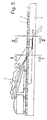
Fig. 3 in verschiedenen Ausführungsvarianten; - Fig. 5
- eine zweite Ausführungsform im schematischen Längsschnitt;
- Fig. 6
- einen Schnitt entlang der Linie 1-1 in
Fig. 5 ; - Fig. 7a
- einen Schnitt entlang der Linie 2-2 in
Fig. 5 in einer ersten Variante; - Fig. 7b
- einen Schnitt entlang der Linie 2-2 in
Fig. 5 in einer zweiten Variante mit einer zusätzlichen Detailvergrößerung. - In den
Fig. 1 bis 4 ist eine erste Ausführungsform und in denFig. 5 bis 7 eine zweite Ausführungsform zum maschinellen Ausbau von Bodenschichten im Gleisbau dargestellt. - Bei der ersten Ausführungsform in den
Fig. 1 bis 4 ist dargestellt, wie ein Gleis 1 auf seinen Schwellen 2 auf dem Boden 3 gelagert ist. Auf dem Gleis 1 sind Bearbeitungsfahrzeuge 4 verfahrbar angeordnet. - Der Boden 3 unterhalb des Gleises 1 soll maschinell ausgebaut werden. Hierzu wird entsprechend der Darstellung in
Fig. 3a zunächst unterhalb des Gleises 1 ein U-förmiger Schnitt 5 durch eine entsprechende Schneidvorrichtung eingebracht. Dieser Schnitt 5 kann durch Schnittbänder mit einem Sägezahn (Fig. 4a ) oder mit einem Fräskopf (Fig. 4b ) erfolgen, aber auch durch eine Beaufschlagung durch Luftdruck (Fig. 4c ) oder mittels Wasserstrahlen (4d). - In dem dargestellten Ausführungsbeispiel ist ein endlos umlaufendes Sägeband 8 vorgesehen, welches U-förmig geführt ist. Statt des Sägebandes 8 könnte auch ein Fräsband verwendet werden. Dies bedeutet, daß die senkrechten Schenkel des "U" den vertikalen Schnitt und die Basis des "U" den horizontalen Schnitt des insgesamt U-förmigen Schnittes 5 einbringen. Indem das endlos umlaufende Sägeband 8 U-förmig geführt ist, bedeutet dies, daß im Bereich der Basis sowie im Bereich der beiden Schenkel des U-Profils entsprechende Abschnitte des Sägebandes 8 dicht nebeneinander sowie parallel zueinander in entgegengesetzte Richtungen laufen. Selbstverständlich ist ein entsprechender Antrieb für das Sägeband 8 vorgesehen.
- Bei der Ausführungsvariante in
Fig. 3b ist ebenfalls ein endlos umlaufendes Sägeband 8 vorgesehen. Dieses ist jedoch nicht in der vorbeschriebenen Weise wie ein "U" geführt, sondern in der Art eines Rechtecks mit einer Mittenöffnung. Dies bedeutet aber, daß der untere Bereich dieses Rechtecks ein U-Profil definiert, welches dem U-förmigen Schnitt 5 entspricht. Statt der rechteckigen Öffnung dieses umlaufenden Sägebandes 8 sind auch andere Profilformen denkbar. - Auf jeden Fall bewirkt der Schnitt 5 eine Trennung des Bodens 3 in eine obere, auszubauende Bodenschicht 6 und einem darunter befindlichen Untergrund 7. Aufgrund dieser sauberen Trennlinie kann die darüber befindliche Bodenschicht 6 maschinell gelöst und abgetragen werden, wie dies in
Fig. 1 schematisch dargestellt ist. - Während der gesamten Prozedur kann das Gleis 1 mit seinen Schwellen 2 entweder nach dem Entfernen der Bodenschicht 6 absacken oder aber das Gleis 1 mit seinen Schwellen 2 wird durch eine entsprechende Hebevorrichtung der Bearbeitungsfahrzeuge 4 gehalten.
- Bei der zweiten Ausführungsform in den
Fig. 5 bis 7 geht es nicht um den maschinellen Ausbau der Bodenschicht 6 unterhalb des Gleises 1, sondern in diesem Fall um den maschinellen Ausbau der Bodenschicht 6 neben dem Gleis 1. - Die Funktionsweise ist vom Grundprinzip her die gleiche wie bei der ersten Ausführungsform, d. h. es wird ein U-förmiger Schnitt 5 in der vorbeschriebenen Weise durchgeführt, um so eine Trennung der abzutragenden Bodenschicht 6 vom Untergrund 7 zu bewirken. Anschließend wird die Bodenschicht 6 wieder maschinell gelöst und abgetragen.
- Bei der Ausführungsvariante in
Fig. 7a ist entsprechend der Variante inFig. 3a wiederum ein endlos umlaufendes Sägeband 8 mit einer U-förmigen Führung vorgesehen, während bei der Variante inFig. 7b entsprechend der Variante inFig. 3b das endlos umlaufende Sägeband 8 ein Rechteck definiert. -
- 1
- Gleis
- 2
- Schwelle
- 3
- Boden
- 4
- Bearbeitungsfahrzeug
- 5
- Schnitt
- 6
- Bodenschicht
- 7
- Untergrund
- 8
- Sägeband
Claims (6)
- Verfahren zum maschinellen Ausbau von Bodenschichten (6) im Gleisbau,
bei dem eine Bodenschicht (6) unterhalb und/oder neben dem Gleis (1) maschinell gelöst und abgetragen wird,
dadurch gekennzeichnet,
daß vor dem maschinellen Lösen und Abtragen der Bodenschicht (6) diese zunächst durch einen zum Gleis (1) im wesentlichen parallelen Schnitt (5) vom darunter befindlichen Untergrund (7) getrennt wird. - Verfahren nach dem vorhergehenden Anspruch,
dadurch gekennzeichnet,
daß der Schnitt (5) im wesentlichen gerade oder wannenförmig oder U-förmig oder in einer anderen geeigneten Profilform durchgeführt wird. - Verfahren nach einem der vorhergehenden Ansprüche,
dadurch gekennzeichnet,
daß zum Schneiden der Boden (3) gesägt und/oder gefräst und/oder mit einem Luftstrahl beaufschlagt und/oder mit einem Wasserstrahl beaufschlagt wird. - Verfahren nach einem der vorhergehenden Ansprüche,
dadurch gekennzeichnet,
daß zum Schneiden ein endlos umlaufendes Sägeband (8) oder Fräsband verwendet wird. - Verfahren nach Anspruch 4,
dadurch gekennzeichnet,
daß das endlos umlaufende Sägeband (8) oder Fräsband in der Art eines U-Profils oder als ringartiges Profil mit einer Mittenöffnung geführt ist. - Vorrichtung zur Durchführung des Verfahrens nach einem der Verfahrensansprüche,
dadurch gekennzeichnet,
daß die Schneideinrichtung auf dem Gleis (1) verfahrbar ist.
Applications Claiming Priority (1)
| Application Number | Priority Date | Filing Date | Title |
|---|---|---|---|
| DE102007036791 | 2007-08-03 |
Publications (2)
| Publication Number | Publication Date |
|---|---|
| EP2020459A1 true EP2020459A1 (de) | 2009-02-04 |
| EP2020459B1 EP2020459B1 (de) | 2010-03-17 |
Family
ID=39925049
Family Applications (1)
| Application Number | Title | Priority Date | Filing Date |
|---|---|---|---|
| EP08011470A Not-in-force EP2020459B1 (de) | 2007-08-03 | 2008-06-25 | Verfahren und Vorrichtung zum maschinellen Ausbau von Bodenschichten im Gleisbau |
Country Status (3)
| Country | Link |
|---|---|
| EP (1) | EP2020459B1 (de) |
| AT (1) | ATE461320T1 (de) |
| DE (1) | DE502008000443D1 (de) |
Cited By (2)
| Publication number | Priority date | Publication date | Assignee | Title |
|---|---|---|---|---|
| CN102259353A (zh) * | 2010-05-25 | 2011-11-30 | 拜耳材料科技(中国)有限公司 | 一种切割聚氨酯铁路道床的方法、装置及其应用 |
| DE202011110788U1 (de) | 2011-02-04 | 2016-05-19 | Michael Stelley | Vorrichtung zum Aufbau und zur Bearbeitung von Gleisanlagen |
Families Citing this family (1)
| Publication number | Priority date | Publication date | Assignee | Title |
|---|---|---|---|---|
| DE102011010427A1 (de) | 2011-02-04 | 2012-08-09 | Michael Stelley | Vorrichtung und Verfahren zum Zerkleinern von Fels/Packlagen zu einem Mineralgemisch unterhalb von Gleisanlagen bei aufgebautem Gleis mit gleisgebundenen Maschinen/Modulen/Aggregaten |
Citations (4)
| Publication number | Priority date | Publication date | Assignee | Title |
|---|---|---|---|---|
| AT349051B (de) | 1977-06-01 | 1979-03-26 | Plasser Bahnbaumasch Franz | Raeum- und foerderkette, insbesondere fuer gleisbettungs-reinigungsmaschinen |
| US4152991A (en) | 1976-09-24 | 1979-05-08 | Caterpillar Tractor Co. | Ripping apparatus |
| DE19848655A1 (de) * | 1998-05-12 | 1999-11-18 | Zueblin Ag | Sanierung von Festen Fahrbahnen |
| DE102005013947A1 (de) * | 2005-03-26 | 2006-10-05 | Pfleiderer Infrastrukturtechnik Gmbh & Co Kg | Verfahren zur Höhenkorrektur einer festen Schienenfahrbahn und feste Schienenfahrbahn |
-
2008
- 2008-06-25 EP EP08011470A patent/EP2020459B1/de not_active Not-in-force
- 2008-06-25 DE DE502008000443T patent/DE502008000443D1/de active Active
- 2008-06-25 AT AT08011470T patent/ATE461320T1/de active
Patent Citations (4)
| Publication number | Priority date | Publication date | Assignee | Title |
|---|---|---|---|---|
| US4152991A (en) | 1976-09-24 | 1979-05-08 | Caterpillar Tractor Co. | Ripping apparatus |
| AT349051B (de) | 1977-06-01 | 1979-03-26 | Plasser Bahnbaumasch Franz | Raeum- und foerderkette, insbesondere fuer gleisbettungs-reinigungsmaschinen |
| DE19848655A1 (de) * | 1998-05-12 | 1999-11-18 | Zueblin Ag | Sanierung von Festen Fahrbahnen |
| DE102005013947A1 (de) * | 2005-03-26 | 2006-10-05 | Pfleiderer Infrastrukturtechnik Gmbh & Co Kg | Verfahren zur Höhenkorrektur einer festen Schienenfahrbahn und feste Schienenfahrbahn |
Cited By (3)
| Publication number | Priority date | Publication date | Assignee | Title |
|---|---|---|---|---|
| CN102259353A (zh) * | 2010-05-25 | 2011-11-30 | 拜耳材料科技(中国)有限公司 | 一种切割聚氨酯铁路道床的方法、装置及其应用 |
| WO2011147761A1 (en) * | 2010-05-25 | 2011-12-01 | Bayer Materialscience Ag | A method and an equipment for cutting a polyurethane railway track bed and the use thereof |
| DE202011110788U1 (de) | 2011-02-04 | 2016-05-19 | Michael Stelley | Vorrichtung zum Aufbau und zur Bearbeitung von Gleisanlagen |
Also Published As
| Publication number | Publication date |
|---|---|
| DE502008000443D1 (de) | 2010-04-29 |
| ATE461320T1 (de) | 2010-04-15 |
| EP2020459B1 (de) | 2010-03-17 |
Similar Documents
| Publication | Publication Date | Title |
|---|---|---|
| DE3621357C1 (de) | Kappsaege zum Ablaengen von Brettern | |
| DE3808825A1 (de) | Vorrichtung zum ausbrechen einer vertiefung | |
| EP2020459B1 (de) | Verfahren und Vorrichtung zum maschinellen Ausbau von Bodenschichten im Gleisbau | |
| DE1427745A1 (de) | Verfahren und Vorrichtung zum Trennen von Tafeln od.dgl. | |
| DE112013002578T5 (de) | Tunnelvortriebsverfahren | |
| DE2202901A1 (de) | Verfahren und Vorrichtung fuer die Zerteilung von Steinbloecken in Platten | |
| DE19749458A1 (de) | Formschneidemaschine | |
| DE19837132C1 (de) | Trennvorrichtung, insbesondere Diagonalsäge | |
| EP2193894B1 (de) | Verfahren zum Zersägen zumindest einer Platte | |
| DE637119C (de) | Vorrichtung zur Gewinnung und Foerderung von Gebirgsschichten | |
| DE102010018171A1 (de) | Verfahren zur Aufbereitung von mit Verstärkungseinlagen versehenen Elastomerteilen sowie Vorrichtung zur Durchführung des Verfahrens | |
| DE1652508A1 (de) | Verfahren und Vorrichtung zur Flaechenbearbeitung von Gesteinsbloecken od.dgl. | |
| DE29710365U1 (de) | Abschneidevorrichtung für stranggepreßte Formkörper | |
| DE2113190B1 (de) | Verfahren und Vorrichtung zum Vortrieb von Strecken und Tunneln | |
| DE102015016687B4 (de) | Vorrichtung und Verfahren zum Schneiden von Belägen | |
| DE545344C (de) | Schneidmaschine zum Abbau von Kohle, Kali u. dgl. | |
| DE60304630T2 (de) | Verfahren und Vorrichtung zum Behandeln von Altschwellen | |
| DE19625039C2 (de) | Kettenschrämgerät zur Schlitzherstellung im Festgestein | |
| EP0751259B1 (de) | Verfahren und Vorrichtung zum Herstellen von Aussparungen in Asphaltschichten | |
| DE1652527C (de) | Vorrichtung zum Wegfräsen der obersten Schicht von gegossenen Leichtbetonkörpern od. dgl | |
| DE2603755A1 (de) | Doppelkettenfoerderer | |
| DE3444519A1 (de) | Verfahren und vorrichtung zur bearbeitung von im querschnitt vorzugsweise kreisfoermigen staeben u.dgl., insbesondere aus holz | |
| DE4127177A1 (de) | Maschine zum schneiden von insbesondere plattenfoermigem schneidgut | |
| DE1801010C3 (de) | Verfahren und Vorrichtung zur Gewinnung und Abförderung im Flözbergbau untertage | |
| EP1349718B1 (de) | Sägeband |
Legal Events
| Date | Code | Title | Description |
|---|---|---|---|
| PUAI | Public reference made under article 153(3) epc to a published international application that has entered the european phase |
Free format text: ORIGINAL CODE: 0009012 |
|
| AK | Designated contracting states |
Kind code of ref document: A1 Designated state(s): AT BE BG CH CY CZ DE DK EE ES FI FR GB GR HR HU IE IS IT LI LT LU LV MC MT NL NO PL PT RO SE SI SK TR |
|
| AX | Request for extension of the european patent |
Extension state: AL BA MK RS |
|
| 17P | Request for examination filed |
Effective date: 20090227 |
|
| 17Q | First examination report despatched |
Effective date: 20090403 |
|
| AKX | Designation fees paid |
Designated state(s): AT BE BG CH CY CZ DE DK EE ES FI FR GB GR HR HU IE IS IT LI LT LU LV MC MT NL NO PL PT RO SE SI SK TR |
|
| GRAP | Despatch of communication of intention to grant a patent |
Free format text: ORIGINAL CODE: EPIDOSNIGR1 |
|
| GRAS | Grant fee paid |
Free format text: ORIGINAL CODE: EPIDOSNIGR3 |
|
| GRAA | (expected) grant |
Free format text: ORIGINAL CODE: 0009210 |
|
| AK | Designated contracting states |
Kind code of ref document: B1 Designated state(s): AT BE BG CH CY CZ DE DK EE ES FI FR GB GR HR HU IE IS IT LI LT LU LV MC MT NL NO PL PT RO SE SI SK TR |
|
| REG | Reference to a national code |
Ref country code: GB Ref legal event code: FG4D Free format text: NOT ENGLISH |
|
| REG | Reference to a national code |
Ref country code: CH Ref legal event code: EP |
|
| REG | Reference to a national code |
Ref country code: IE Ref legal event code: FG4D |
|
| REF | Corresponds to: |
Ref document number: 502008000443 Country of ref document: DE Date of ref document: 20100429 Kind code of ref document: P |
|
| REG | Reference to a national code |
Ref country code: CH Ref legal event code: NV Representative=s name: SCHNEIDER FELDMANN AG PATENT- UND MARKENANWAELTE |
|
| REG | Reference to a national code |
Ref country code: NL Ref legal event code: VDEP Effective date: 20100317 |
|
| PG25 | Lapsed in a contracting state [announced via postgrant information from national office to epo] |
Ref country code: LT Free format text: LAPSE BECAUSE OF FAILURE TO SUBMIT A TRANSLATION OF THE DESCRIPTION OR TO PAY THE FEE WITHIN THE PRESCRIBED TIME-LIMIT Effective date: 20100317 Ref country code: HR Free format text: LAPSE BECAUSE OF FAILURE TO SUBMIT A TRANSLATION OF THE DESCRIPTION OR TO PAY THE FEE WITHIN THE PRESCRIBED TIME-LIMIT Effective date: 20100317 Ref country code: NO Free format text: LAPSE BECAUSE OF FAILURE TO SUBMIT A TRANSLATION OF THE DESCRIPTION OR TO PAY THE FEE WITHIN THE PRESCRIBED TIME-LIMIT Effective date: 20100617 |
|
| LTIE | Lt: invalidation of european patent or patent extension |
Effective date: 20100317 |
|
| PG25 | Lapsed in a contracting state [announced via postgrant information from national office to epo] |
Ref country code: PL Free format text: LAPSE BECAUSE OF FAILURE TO SUBMIT A TRANSLATION OF THE DESCRIPTION OR TO PAY THE FEE WITHIN THE PRESCRIBED TIME-LIMIT Effective date: 20100317 Ref country code: SI Free format text: LAPSE BECAUSE OF FAILURE TO SUBMIT A TRANSLATION OF THE DESCRIPTION OR TO PAY THE FEE WITHIN THE PRESCRIBED TIME-LIMIT Effective date: 20100317 Ref country code: FI Free format text: LAPSE BECAUSE OF FAILURE TO SUBMIT A TRANSLATION OF THE DESCRIPTION OR TO PAY THE FEE WITHIN THE PRESCRIBED TIME-LIMIT Effective date: 20100317 Ref country code: LV Free format text: LAPSE BECAUSE OF FAILURE TO SUBMIT A TRANSLATION OF THE DESCRIPTION OR TO PAY THE FEE WITHIN THE PRESCRIBED TIME-LIMIT Effective date: 20100317 |
|
| REG | Reference to a national code |
Ref country code: IE Ref legal event code: FD4D |
|
| PG25 | Lapsed in a contracting state [announced via postgrant information from national office to epo] |
Ref country code: CY Free format text: LAPSE BECAUSE OF FAILURE TO SUBMIT A TRANSLATION OF THE DESCRIPTION OR TO PAY THE FEE WITHIN THE PRESCRIBED TIME-LIMIT Effective date: 20100317 Ref country code: ES Free format text: LAPSE BECAUSE OF FAILURE TO SUBMIT A TRANSLATION OF THE DESCRIPTION OR TO PAY THE FEE WITHIN THE PRESCRIBED TIME-LIMIT Effective date: 20100628 Ref country code: SE Free format text: LAPSE BECAUSE OF FAILURE TO SUBMIT A TRANSLATION OF THE DESCRIPTION OR TO PAY THE FEE WITHIN THE PRESCRIBED TIME-LIMIT Effective date: 20100317 Ref country code: RO Free format text: LAPSE BECAUSE OF FAILURE TO SUBMIT A TRANSLATION OF THE DESCRIPTION OR TO PAY THE FEE WITHIN THE PRESCRIBED TIME-LIMIT Effective date: 20100317 Ref country code: NL Free format text: LAPSE BECAUSE OF FAILURE TO SUBMIT A TRANSLATION OF THE DESCRIPTION OR TO PAY THE FEE WITHIN THE PRESCRIBED TIME-LIMIT Effective date: 20100317 Ref country code: GR Free format text: LAPSE BECAUSE OF FAILURE TO SUBMIT A TRANSLATION OF THE DESCRIPTION OR TO PAY THE FEE WITHIN THE PRESCRIBED TIME-LIMIT Effective date: 20100618 Ref country code: EE Free format text: LAPSE BECAUSE OF FAILURE TO SUBMIT A TRANSLATION OF THE DESCRIPTION OR TO PAY THE FEE WITHIN THE PRESCRIBED TIME-LIMIT Effective date: 20100317 |
|
| PG25 | Lapsed in a contracting state [announced via postgrant information from national office to epo] |
Ref country code: CZ Free format text: LAPSE BECAUSE OF FAILURE TO SUBMIT A TRANSLATION OF THE DESCRIPTION OR TO PAY THE FEE WITHIN THE PRESCRIBED TIME-LIMIT Effective date: 20100317 Ref country code: SK Free format text: LAPSE BECAUSE OF FAILURE TO SUBMIT A TRANSLATION OF THE DESCRIPTION OR TO PAY THE FEE WITHIN THE PRESCRIBED TIME-LIMIT Effective date: 20100317 Ref country code: BG Free format text: LAPSE BECAUSE OF FAILURE TO SUBMIT A TRANSLATION OF THE DESCRIPTION OR TO PAY THE FEE WITHIN THE PRESCRIBED TIME-LIMIT Effective date: 20100617 Ref country code: IS Free format text: LAPSE BECAUSE OF FAILURE TO SUBMIT A TRANSLATION OF THE DESCRIPTION OR TO PAY THE FEE WITHIN THE PRESCRIBED TIME-LIMIT Effective date: 20100717 |
|
| BERE | Be: lapsed |
Owner name: ZURCHER, RALF Effective date: 20100630 |
|
| PLBE | No opposition filed within time limit |
Free format text: ORIGINAL CODE: 0009261 |
|
| STAA | Information on the status of an ep patent application or granted ep patent |
Free format text: STATUS: NO OPPOSITION FILED WITHIN TIME LIMIT |
|
| PG25 | Lapsed in a contracting state [announced via postgrant information from national office to epo] |
Ref country code: MC Free format text: LAPSE BECAUSE OF NON-PAYMENT OF DUE FEES Effective date: 20100630 Ref country code: DK Free format text: LAPSE BECAUSE OF FAILURE TO SUBMIT A TRANSLATION OF THE DESCRIPTION OR TO PAY THE FEE WITHIN THE PRESCRIBED TIME-LIMIT Effective date: 20100317 Ref country code: IE Free format text: LAPSE BECAUSE OF FAILURE TO SUBMIT A TRANSLATION OF THE DESCRIPTION OR TO PAY THE FEE WITHIN THE PRESCRIBED TIME-LIMIT Effective date: 20100317 |
|
| 26N | No opposition filed |
Effective date: 20101220 |
|
| REG | Reference to a national code |
Ref country code: FR Ref legal event code: ST Effective date: 20110228 |
|
| PG25 | Lapsed in a contracting state [announced via postgrant information from national office to epo] |
Ref country code: IT Free format text: LAPSE BECAUSE OF FAILURE TO SUBMIT A TRANSLATION OF THE DESCRIPTION OR TO PAY THE FEE WITHIN THE PRESCRIBED TIME-LIMIT Effective date: 20100317 |
|
| PG25 | Lapsed in a contracting state [announced via postgrant information from national office to epo] |
Ref country code: MT Free format text: LAPSE BECAUSE OF FAILURE TO SUBMIT A TRANSLATION OF THE DESCRIPTION OR TO PAY THE FEE WITHIN THE PRESCRIBED TIME-LIMIT Effective date: 20100317 |
|
| PG25 | Lapsed in a contracting state [announced via postgrant information from national office to epo] |
Ref country code: FR Free format text: LAPSE BECAUSE OF NON-PAYMENT OF DUE FEES Effective date: 20100630 |
|
| PG25 | Lapsed in a contracting state [announced via postgrant information from national office to epo] |
Ref country code: BE Free format text: LAPSE BECAUSE OF NON-PAYMENT OF DUE FEES Effective date: 20100630 |
|
| PG25 | Lapsed in a contracting state [announced via postgrant information from national office to epo] |
Ref country code: LU Free format text: LAPSE BECAUSE OF NON-PAYMENT OF DUE FEES Effective date: 20100625 Ref country code: HU Free format text: LAPSE BECAUSE OF FAILURE TO SUBMIT A TRANSLATION OF THE DESCRIPTION OR TO PAY THE FEE WITHIN THE PRESCRIBED TIME-LIMIT Effective date: 20100918 Ref country code: PT Free format text: LAPSE BECAUSE OF FAILURE TO SUBMIT A TRANSLATION OF THE DESCRIPTION OR TO PAY THE FEE WITHIN THE PRESCRIBED TIME-LIMIT Effective date: 20100817 |
|
| PG25 | Lapsed in a contracting state [announced via postgrant information from national office to epo] |
Ref country code: TR Free format text: LAPSE BECAUSE OF FAILURE TO SUBMIT A TRANSLATION OF THE DESCRIPTION OR TO PAY THE FEE WITHIN THE PRESCRIBED TIME-LIMIT Effective date: 20100317 |
|
| GBPC | Gb: european patent ceased through non-payment of renewal fee |
Effective date: 20120625 |
|
| PG25 | Lapsed in a contracting state [announced via postgrant information from national office to epo] |
Ref country code: GB Free format text: LAPSE BECAUSE OF NON-PAYMENT OF DUE FEES Effective date: 20120625 |
|
| REG | Reference to a national code |
Ref country code: DE Ref legal event code: R082 Ref document number: 502008000443 Country of ref document: DE Representative=s name: MEPAT PATENTANWAELTE, DR. MEHL-MIKUS, GOY, DR., DE |
|
| REG | Reference to a national code |
Ref country code: CH Ref legal event code: PFA Owner name: ZUERCHER, RALF, DE Free format text: FORMER OWNER: ZUERCHER, RALF, DE |
|
| PGFP | Annual fee paid to national office [announced via postgrant information from national office to epo] |
Ref country code: DE Payment date: 20210621 Year of fee payment: 14 |
|
| PGFP | Annual fee paid to national office [announced via postgrant information from national office to epo] |
Ref country code: AT Payment date: 20210618 Year of fee payment: 14 Ref country code: CH Payment date: 20210623 Year of fee payment: 14 |
|
| REG | Reference to a national code |
Ref country code: DE Ref legal event code: R119 Ref document number: 502008000443 Country of ref document: DE |
|
| REG | Reference to a national code |
Ref country code: CH Ref legal event code: PL |
|
| REG | Reference to a national code |
Ref country code: AT Ref legal event code: MM01 Ref document number: 461320 Country of ref document: AT Kind code of ref document: T Effective date: 20220625 |
|
| PG25 | Lapsed in a contracting state [announced via postgrant information from national office to epo] |
Ref country code: LI Free format text: LAPSE BECAUSE OF NON-PAYMENT OF DUE FEES Effective date: 20220630 Ref country code: CH Free format text: LAPSE BECAUSE OF NON-PAYMENT OF DUE FEES Effective date: 20220630 Ref country code: AT Free format text: LAPSE BECAUSE OF NON-PAYMENT OF DUE FEES Effective date: 20220625 |
|
| PG25 | Lapsed in a contracting state [announced via postgrant information from national office to epo] |
Ref country code: DE Free format text: LAPSE BECAUSE OF NON-PAYMENT OF DUE FEES Effective date: 20230103 |