EP2020460A2 - Dispositif de transition d'un mur de protection en béton à une barrière de sécurité en acier sur routes - Google Patents
Dispositif de transition d'un mur de protection en béton à une barrière de sécurité en acier sur routes Download PDFInfo
- Publication number
- EP2020460A2 EP2020460A2 EP08013720A EP08013720A EP2020460A2 EP 2020460 A2 EP2020460 A2 EP 2020460A2 EP 08013720 A EP08013720 A EP 08013720A EP 08013720 A EP08013720 A EP 08013720A EP 2020460 A2 EP2020460 A2 EP 2020460A2
- Authority
- EP
- European Patent Office
- Prior art keywords
- hood
- concrete
- chamber
- transition device
- transition
- Prior art date
- Legal status (The legal status is an assumption and is not a legal conclusion. Google has not performed a legal analysis and makes no representation as to the accuracy of the status listed.)
- Granted
Links
Images



Classifications
-
- E—FIXED CONSTRUCTIONS
- E01—CONSTRUCTION OF ROADS, RAILWAYS, OR BRIDGES
- E01F—ADDITIONAL WORK, SUCH AS EQUIPPING ROADS OR THE CONSTRUCTION OF PLATFORMS, HELICOPTER LANDING STAGES, SIGNS, SNOW FENCES, OR THE LIKE
- E01F15/00—Safety arrangements for slowing, redirecting or stopping errant vehicles, e.g. guard posts or bollards; Arrangements for reducing damage to roadside structures due to vehicular impact
- E01F15/02—Continuous barriers extending along roads or between traffic lanes
- E01F15/04—Continuous barriers extending along roads or between traffic lanes essentially made of longitudinal beams or rigid strips supported above ground at spaced points
- E01F15/0407—Metal rails
-
- E—FIXED CONSTRUCTIONS
- E01—CONSTRUCTION OF ROADS, RAILWAYS, OR BRIDGES
- E01F—ADDITIONAL WORK, SUCH AS EQUIPPING ROADS OR THE CONSTRUCTION OF PLATFORMS, HELICOPTER LANDING STAGES, SIGNS, SNOW FENCES, OR THE LIKE
- E01F15/00—Safety arrangements for slowing, redirecting or stopping errant vehicles, e.g. guard posts or bollards; Arrangements for reducing damage to roadside structures due to vehicular impact
- E01F15/02—Continuous barriers extending along roads or between traffic lanes
- E01F15/08—Continuous barriers extending along roads or between traffic lanes essentially made of walls or wall-like elements ; Cable-linked blocks
- E01F15/081—Continuous barriers extending along roads or between traffic lanes essentially made of walls or wall-like elements ; Cable-linked blocks characterised by the use of a specific material
- E01F15/083—Continuous barriers extending along roads or between traffic lanes essentially made of walls or wall-like elements ; Cable-linked blocks characterised by the use of a specific material using concrete
Definitions
- the invention relates to a transition device from a concrete protective wall to a steel safety barrier on roads having the features of the preamble of claim 1.
- a concrete protection wall has regularly on the road side, with a double-sided concrete protection wall on both sides, a beveled base and towering over then the actual protective wall, which extends up to a height of about 90 cm regularly.
- the impact surfaces of the concrete protective wall are directed obliquely to the roadway, so that a vehicle is deflected back in an impact in the direction of the road.
- the height of the concrete protection wall depends on the requirements of the traffic route. It is intended to prevent the concrete protective wall from being run over by vehicles which normally travel on the traffic route.
- a concrete protective wall redirects the vehicle back onto the road in the event of a lesser impact, for example of a car, without seriously destroying energy. In a strong impact, the concrete protective wall is destroyed.
- the teaching of the present invention is concerned.
- the basic problem of such a transition device is that the concrete protection wall has a completely different cross-section than the steel guardrail and that the concrete barrier is rigid, while the steel guard rail deliberately evades in a collision in an impact.
- the transition structure is part of the concrete protection wall. It has an increasingly changing cross section towards the outlet end.
- the concrete protection wall in its transition structure forming portion on a mounting surface, which is set back from the longitudinal side surface of the concrete protection wall otherwise such that the size of the offset of the depth of the spar or the two superimposed bars corresponds to the steel guardrail.
- the concrete attachment section merges into a concrete discharge section with a depth substantially constant in the longitudinal direction but decreasing to zero.
- the horizontally extending spars are supported by posts in increasingly large intervals.
- a transition device from a concrete protective wall to a steel safety barrier on roads ( DE-U-20 2005 008 391 ), in which the transition structure is a hood, in particular made of sheet steel, which is placed over a certain length piece on the end of the concrete protection wall and then further hollow from the end of the concrete protection wall to corresponding, anchored in the ground post.
- this bonnet made of steel sheet changes its contour from the contour of the concrete protective wall to a substantially box-shaped contour with a substantially vertically oriented and longitudinally extending attachment surface to which the spars of the steel guardrail are bolted.
- the change in longitudinal restraint properties from the concrete protection wall to the steel guardrail is significantly dependent on anchoring the hood by means of the posts anchored in the ground.
- the teaching is based on the problem at the outset explained, the starting point forming transition device to design and further that it is inexpensive to produce, inexpensive after a collision interchangeable or repairable and also in the longitudinal direction continuously changing retention properties.
- the transitional construction is not a different sized part of the concrete protection wall, but rather the concrete protection wall ends at a substantially vertically oriented end face. This is followed, possibly also with a small distance, in the longitudinal direction to a substantially over the entire transition distance extending concrete poured foundation.
- This foundation forms the massive concrete cast spine of the transitional structure.
- This transitional construction is inventively in the form of a top mounted on the foundation hood, which consists in particular of sheet steel. It may be that in the course of further developments in the future also plastic fiber composite materials will be considered. Currently, steel sheet of appropriate thickness (for example, 6 mm) is the preferred material for the hood.
- the hollow itself hood is anchored to the concrete barrier by means of emerging there reinforcing elements.
- the hood in the region of the emerging from the concrete barrier reinforcing elements is poured within a trained in the hood chamber with concrete.
- the hood thus forms with its separated by a sheet pile chamber the shuttering for pouring concrete.
- the resulting concrete block within the hood forms the massive anchor point of the hood on the concrete barrier.
- the retention properties of the transition structure change only within the hood itself, namely from the region of the chamber to the end of the hood facing away from there.
- the transitional construction forming, in particular made of sheet steel hood extends to the end of the transition zone, so regularly to the end or close to the end of the foundation. Even there, ie at its end facing away from the concrete protective wall, the hood is anchored to the foundation. It is bolted to the foundation there or otherwise firmly connected to this. This results in the second, from the front side of the concrete protection wall solid anchoring point of the hood on the foundation.
- the production of the transition device on site is comparatively simple and inexpensive.
- the hood can be replaced relatively quickly and inexpensively in a vehicle collision. After all can be influenced by the design of the hood, the course of the retention properties in the longitudinal direction.
- the emerging from the concrete barrier reinforcing elements can be, for example, five to six rebars, each with a diameter of 16 mm. These protrude from the front of the concrete barrier about as far as the depth of the chamber of the hood allows it, for example, about 1.2 m.
- the anchoring can be further improved by the fact that the foundation has in the region of the chamber of the hood upstanding reinforcing elements, which are embedded after pouring the chamber with concrete in this concrete.
- a concrete filling opening at the top of the hood in the area of the chamber is recommended.
- a second opening as a vent for the filled of the hood is recommended.
- transition device according to the invention can be further developed and developed in a variety of directions. For this, reference may be made to the subclaims concerning the transition device. These will be explained later in connection with the explanation of a preferred embodiment with reference to the drawing in detail and with their specifics.
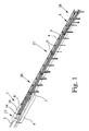
- the invention relates to a transition device on a roadway 1, the in Fig. 1 is indicated by the line defining the line edge, of a concrete protection wall 2 on a steel barrier 3.
- the embodiment shows an embodiment of a one-sided concrete barrier 2.
- the teaching of the invention also applies to two-sided or double-sided concrete barriers.
- the transition device must then be adapted accordingly to a double-sided design.
- a “prayer protection wall” in the sense of teaching may also be a concrete-plastic mixed construction or a plastic-fiber composite construction, provided that the regulations for passive safety devices on roads permit this.
- a “steel guardrail” within the meaning of the teachings of the invention may also be a plastic or plastic fiber composite plank construction, if permitted by the guidelines for roadside passive guards.
- FIG. 1 On the left, the concrete protection wall 2 and on the right the steel safety barrier 3 with an upper rail 4 and a lower rail 5, which can be seen in FIG Fig. 1 rightmost already lowered down to the ground.
- the lower spar 5 In the course of the steel guardrail 3, the lower spar 5 is no longer continued.
- the spars 4, 5 are supported by posts 6, which in Fig. 1 rammed into the ground to the right, as prescribed by the guidelines for passive road safety. For harder ground, the posts 6 can also be dowelled on a foundation with foot plates.
- the concrete protective wall 2 and the steel guardrail 3 define with their course a longitudinal direction, whereby also a slightly arcuate course of the lane 1 should be included accordingly.
- a foundation 8 In the longitudinal direction extends over a certain transition section 7, a foundation 8, on which a transition structure 9 according to the invention is located. You can find the foundation 8 in Fig. 1 indicated, one recognizes the foundation also in the sections B, C and D in Fig. 3 , It is a normal, sufficiently deep, concrete-poured foundation.
- transition structure 9 at a distance from the concrete protective wall 2 end facing the roadway has a substantially vertically oriented and longitudinally extending attachment surface 10, at least one spar of the steel guardrail 3, here the upper and lower bars 4, 5 of Steel guardrail 3 are mounted.
- the construction of the transition device according to the invention corresponds to what is already known from the prior art.
- FIG. 2 drawn in, in Fig. 3A section A shown shows the cross section of the concrete protection wall 2, which has been equipped here with the transition structure 9 according to the invention.
- Fig. 3B are emerging end reinforcing elements 12 indicated in the form of five superposed reinforcing steels. Typically, this can be a reinforcing steel with a diameter of 16 mm, which is embedded to the concrete protection wall 2 out about 10 m wide and beyond the front side 11 of the concrete protection wall 2 by a suitable dimension.
- transition structure 9 is designed as a top mounted on the foundation 8 hood 9, in particular consisting of sheet steel. Also in this regard, the introductory note applies that in the course of time, other materials, in particular plastic-fiber composite materials for the hood 9 may come into question.
- Fig. 4 and 5 indicate that the hood 9 is initially hollow. It is open at the end 11 of the concrete barrier wall 2 facing end. Inside, at a distance from the open end, it has a substantially vertically oriented sheet pile wall 14 separating a chamber 13. The sheet pile wall 14 is in Fig. 4 and 5 indicated, it lies transversely within the hood. 9
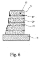
- the emerging from the concrete barrier reinforcing elements 12 are matched in length to the clear length of the chamber 13 and are in the chamber 13 of the hood 9, as soon as the hood 9 has been placed on the foundation 8. In this state, the chamber 13 is filled with concrete 15 ( Fig. 6 ).
- the cut in Fig. 3B has dispensed with the drawing of the concrete 15 in order to recognize the end face 11 and the reinforcing elements 12 can.
- the illustrated embodiment shows a bottom open hood 9.
- This hood 9 can be removed from the block cast concrete 15 if necessary. Here you can pour the concrete 15 only in the chamber 13 and can rest on the foundation 8, without realizing additional reinforcement.
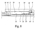
- Fig. 2 and Fig. 8 both show the further peculiarity of the transition device according to the invention, which consists in that the foundation 8 then extends in the longitudinal direction substantially over the entire transition section 7 on the end face 11 of the concrete protection wall 2 and thus thus forms the backbone of the transition device.
- the hood 9 is also anchored on the end facing away from the concrete protective wall 2 on the foundation 8, here for example by screwing by means of several threaded bolts whose counterparts are embedded in the foundation 8.
- Fig. 8 also shows a vent 16 '.
- the hood 9 to the concrete protection wall 2 on the one hand and to the steel guardrail 3 on the other requires for the hood 9 a complex, changing in the longitudinal direction cross-sectional shape.
- the height of the hood 9 on the concrete protection wall 2 facing end corresponds approximately to the height of the concrete protection wall 2.
- the hood 9 on the concrete protective wall 2 end facing the roadway has substantially the same contour as the concrete protective wall. 2
- the concrete protection wall 2 is symmetrical in cross-section, but has only one side of the roadway. It works therefore sided.
- the hood 9 is widened box-shaped on the opposite side of the roadway 1.
- Fig. 3B it can be seen that the hood 9 on the concrete protective wall 2 end facing one of the contour of the concrete protection wall 2 has corresponding recess so that when pouring the concrete 15, the desired connection to the concrete protection wall 2 is made.
- the hood 9 is therefore not only at the bottom, but also the front side to the concrete protection wall 2, here in the region of the recess, open.
- the hood 9 as a rule will generally receive the contour of the concrete protective wall 2 on both sides.
- hood 9 The cross-sectional configuration of the hood 9 described above applies to the end of the concrete protection wall 2 or a section of the hood 9 adjoining it.
- the hood 9 in the region of the chamber 13 corresponds in the longitudinal direction of a substantially concrete protection wall 2 Contour merges into a more box-shaped contour.
- the illustrated and preferred embodiment shows that here the transition in a about half of the chamber 13 engaging, from the concrete protection wall 2 facing the end of the hood 9 spaced section 17 takes place.
- the teaching of the invention also aims to be able to replace the hood 9 as inexpensively as possible after a collision of a vehicle.
- the invention teaches that the hood 9 in the interior of the chamber 13 has a detachment of the hood 9 from the concrete facilitating coating, support or intermediate layer.
- this corresponds to the already given contour of the concrete protective wall 2
- this also facilitates the removal of the hood 9 from the 13 formed in the chamber 13 by pouring concrete concrete block.
- An intermediate layer of a few millimeters thickness, for example of foam plastic is completely uncritical for the impact properties, but facilitates the replacement of the hood 9 enormous.
- Fig. 6 shows a section through the hood 9 in the chamber 13 with the cast therein concrete 15 and the embedded threaded sleeve 20. Because the threaded sleeves 20 are not connected to the hood 9, the screws 19 for removing the hood 9 from the threaded sleeves 20 are unscrewed, which remain even in the concrete 15. In particular, it is recommended that at least two each at the same height threaded sleeves 20 are aligned with each other via a connecting element 21 and further embedded in the concrete 15. This shows too Fig. 6 ,
- the sheet pile wall 14 does not necessarily have to be straight, it is also possible to provide that an offset or a step is found in the sheet pile wall 14 transversely to the longitudinal direction.
- the mounting surface 10 is arranged on the hood 9 viewed from the chamber 13 beyond the sheet pile wall 14. It is advisable to take into account the depth of the spars 4, 5 of the steel guardrail 3 in that the mounting surface 10 is reset to the hood 9 with respect to the longitudinal side surface of the hood 9 in the region of the chamber 13 and that, preferably, the size the offset about the depth of the spar 4 of the steel guardrail 3 corresponds.
- the mounting surface 10 is reset to the hood 9 with respect to the longitudinal side surface of the hood 9 in the region of the chamber 13 and that, preferably, the size the offset about the depth of the spar 4 of the steel guardrail 3 corresponds.
- hood 9 in the region of the mounting surface 10 at the top or, preferably, on the back has an engagement opening for assembly work. Otherwise, you would have the hood 9 at the holes 23 also with, now, however, provided with the hood 9 firmly connected threaded connector, which would cause unnecessary expense.
- a rear engagement opening, in a double-sided concrete protection wall 2 associated hood 9 will need to intervene from above.
- Fig. 4 and 5 The further design of the cross section of the hood 9 is shown in the illustrated and preferred embodiment Fig. 4 and 5 chosen so that the hood 9 has a subsequent to the chamber 13 mounting portion 24 with a substantially constant depth and height in the longitudinal direction.
- the embodiment according to Fig. 8 has constant height continuous attachment portions 24, 24 'and only at the very end of a short, re-receding spout portion 25.
- the construction according to Fig. 1 to 6 a spout portion 25 which adjoins the attachment portion 24 and has a substantially constant depth but a decreasing height.
- the transition device according to the invention attacks the named from the prior art construction of a spout section, which, however, here part of the existing steel sheet hood 9, that is not cast from concrete.
- the longitudinal extent of the attachment portion 24 need not be as large as in FIG Fig. 4 and 5 shown. In an extreme case, the attachment section 24 may degenerate to a short distance or may completely rise in the outlet section 25. Then you would have only the chamber 13 and then immediately following the outlet section 25, but then the entire mounting surface 10 included.
- the mounting surface 10 of the hood 9 extends into the outlet portion 25 and the hood 9 is also provided in the outlet portion 25 with holes 23 for attachment of the spar 4 of the steel guard rail 3.
- top view in Fig. 5 indicates that in the illustrated and preferred embodiment, the hood 9 is anchored again at its end remote from the concrete protective wall 2 end. It is envisaged that the hood 9 is screwed at the end of the outlet section 25 to the foundation 8 or otherwise firmly connected.
- Fig. 8 shows Fig. 8 a so far improved construction, which is characterized in that the anchorage 9 'of the hood 9 at the end remote from the concrete protective wall 2 end behind the spar 4 and opposite the roadway side of the foundation 8 is set far back.
- the anchorage 9 'here is beyond the longitudinal center line of the foundation 8, ie in a rearward region, which can no longer be reached even in the case of a strong impact from a tire of a vehicle.
- Fig. 1 indicates that the transition to the steel guardrail 3 posts 6 may already require in the area of the hood 9.
- Fig. 5 can be seen that to do this, the hood 9 on its upper side with foot caps or mounting surfaces, Here in each case square holes 25 ', is provided for post 6 of the steel guardrail 3. In Fig. 1 you can see this transition very well.
- the hood 9 has a length of about 4 m to 5 m
- the chamber 13 of the hood 9 has a length of about 1.0 m to 1.5 m, in the illustrated embodiment about 1.3 m. This fits the measure of 1.2 m for the protruding reinforcing elements 12 of the concrete protective wall 2.
- the mounting portion 24 has a length of about 1.2 m
- the outlet portion 25 has a length of about 2 m with subsequent plate 25 "for screwing with the Foundation 8.
- the dimension of the hood 9 complies with the guidelines for the design of such transitional devices, which results in a dimensioning of the sections in the range of 4 m. Changed policies and regulations may lead to other measures of length in the future.
- Fig. 1 shows, it is recommended for the transition device according to the invention that in the longitudinal direction of the hood 9, a first intermediate portion 26 of the steel guardrail 3 with lateral pressure plates 27 anchored in the ground post 6, this results in an intermediate section 26 with very high, through the Pressure plates 27 in the ground on the post 6 realized retention properties.
- the illustrated embodiment shows that in the longitudinal direction of the first intermediate portion 26, a second intermediate portion 28 with normal anchored in the ground post 6 connects. Here are still both spars 4, 5, the posts 6 but no pressure plates 27 more.
- intermediate sections 26, 28, 29 is also recommended a length of 3.5 to 5 m, preferably of about 4 m.
- the lowermost spar of the steel guardrail 3 in the region of the transitional structure 9 is positioned lower than the typical wheel center height of a passenger car.
Landscapes
- Engineering & Computer Science (AREA)
- Architecture (AREA)
- Civil Engineering (AREA)
- Structural Engineering (AREA)
- Refuge Islands, Traffic Blockers, Or Guard Fence (AREA)
Applications Claiming Priority (1)
| Application Number | Priority Date | Filing Date | Title |
|---|---|---|---|
| DE202007010798U DE202007010798U1 (de) | 2007-08-01 | 2007-08-01 | Übergangsvorrichtung von einer Betonschutzwand auf eine Stahlschutzplanke an Straßen |
Publications (3)
| Publication Number | Publication Date |
|---|---|
| EP2020460A2 true EP2020460A2 (fr) | 2009-02-04 |
| EP2020460A3 EP2020460A3 (fr) | 2013-01-23 |
| EP2020460B1 EP2020460B1 (fr) | 2014-01-29 |
Family
ID=39951633
Family Applications (1)
| Application Number | Title | Priority Date | Filing Date |
|---|---|---|---|
| EP20080013720 Active EP2020460B1 (fr) | 2007-08-01 | 2008-07-31 | Dispositif de transition d'un mur de protection en béton à une barrière de sécurité en acier sur routes |
Country Status (2)
| Country | Link |
|---|---|
| EP (1) | EP2020460B1 (fr) |
| DE (1) | DE202007010798U1 (fr) |
Cited By (6)
| Publication number | Priority date | Publication date | Assignee | Title |
|---|---|---|---|---|
| DE202012001738U1 (de) | 2012-02-21 | 2013-05-22 | Eurovia Beton Gmbh | Verbindungsvorrichtung für eine Betonschutzwand an Straßen |
| GB2573745A (en) * | 2018-05-04 | 2019-11-20 | Pell & Baldwin Fabrications Ltd | Temporary bridge parapet protection railing |
| CN111560886A (zh) * | 2020-06-17 | 2020-08-21 | 中交第一公路勘察设计研究院有限公司 | 高速公路中央分隔带梁柱式护栏过渡段 |
| CN112482215A (zh) * | 2020-11-20 | 2021-03-12 | 天津市公路工程总公司 | 一种桥头过渡段混凝土防撞护栏与波形钢护栏连接结构及施工方法 |
| CN113293693A (zh) * | 2021-05-12 | 2021-08-24 | 广东省交通规划设计研究院集团股份有限公司 | 一种处于宽度受限中央分隔带上的桥墩防撞装置 |
| CN114457729A (zh) * | 2022-02-28 | 2022-05-10 | 北京深华达交通工程检测有限公司 | 一种q460材料钢混护栏标准过渡段 |
Families Citing this family (4)
| Publication number | Priority date | Publication date | Assignee | Title |
|---|---|---|---|---|
| DE202013004918U1 (de) * | 2013-05-29 | 2014-09-03 | Tss Technische Sicherheits-Systeme Gmbh | Übergangskonstruktion für Fahrbahnbegrenzungen |
| KR102087262B1 (ko) * | 2017-12-19 | 2020-03-10 | 주식회사 국제에스티 | 가드레일의 전이구간용 충격흡수장치 |
| CN112411370A (zh) * | 2020-11-20 | 2021-02-26 | 上海市政工程设计研究总院(集团)有限公司 | 桥梁防撞护栏连接装置及桥梁 |
| CN114411550A (zh) * | 2022-02-17 | 2022-04-29 | 中铁二院工程集团有限责任公司 | 金属梁柱式护栏与混凝土护栏过渡连接结构 |
Citations (3)
| Publication number | Priority date | Publication date | Assignee | Title |
|---|---|---|---|---|
| DE3742356A1 (de) | 1987-12-14 | 1989-06-29 | Sps Schutzplanken Gmbh | Uebergang bei verkehrswegen von einer betongleitwand auf schutzplanken |
| DE202005002859U1 (de) | 2005-02-21 | 2005-05-04 | Spig Schutzplanken-Produktions-Gesellschaft Mbh & Co. Kg | Leitplankenanordnung |
| DE202005008391U1 (de) | 2005-05-25 | 2005-09-08 | Sps Schutzplanken Gmbh | Übergang bei Verkehrswegen von einer Betongleitwand auf eine Schutzplankenanordnung |
Family Cites Families (4)
| Publication number | Priority date | Publication date | Assignee | Title |
|---|---|---|---|---|
| DE8914143U1 (de) * | 1989-11-30 | 1990-01-25 | SPS Schutzplanken GmbH, 8750 Aschaffenburg | Übergang bei Verkehrswegen von einer Gleitwand auf eine Schutzplankeneinrichtung |
| DE29707447U1 (de) * | 1997-04-24 | 1997-11-06 | SPS Schutzplanken GmbH, 63743 Aschaffenburg | Übergang bei Verkehrswegen von einer Betongleitwand auf eine Schutzplankeneinrichtung |
| DE202006015433U1 (de) * | 2006-09-01 | 2007-02-08 | Sps Schutzplanken Gmbh | Übergangskonstruktion |
| DE202006017431U1 (de) * | 2006-11-14 | 2007-02-22 | Sps Schutzplanken Gmbh | Übergangskonstruktion mit Betonelementen |
-
2007
- 2007-08-01 DE DE202007010798U patent/DE202007010798U1/de not_active Expired - Lifetime
-
2008
- 2008-07-31 EP EP20080013720 patent/EP2020460B1/fr active Active
Patent Citations (3)
| Publication number | Priority date | Publication date | Assignee | Title |
|---|---|---|---|---|
| DE3742356A1 (de) | 1987-12-14 | 1989-06-29 | Sps Schutzplanken Gmbh | Uebergang bei verkehrswegen von einer betongleitwand auf schutzplanken |
| DE202005002859U1 (de) | 2005-02-21 | 2005-05-04 | Spig Schutzplanken-Produktions-Gesellschaft Mbh & Co. Kg | Leitplankenanordnung |
| DE202005008391U1 (de) | 2005-05-25 | 2005-09-08 | Sps Schutzplanken Gmbh | Übergang bei Verkehrswegen von einer Betongleitwand auf eine Schutzplankenanordnung |
Cited By (8)
| Publication number | Priority date | Publication date | Assignee | Title |
|---|---|---|---|---|
| DE202012001738U1 (de) | 2012-02-21 | 2013-05-22 | Eurovia Beton Gmbh | Verbindungsvorrichtung für eine Betonschutzwand an Straßen |
| GB2573745A (en) * | 2018-05-04 | 2019-11-20 | Pell & Baldwin Fabrications Ltd | Temporary bridge parapet protection railing |
| GB2573745B (en) * | 2018-05-04 | 2021-10-27 | Pell & Baldwin Fabrications Ltd | Temporary bridge parapet protection railing |
| CN111560886A (zh) * | 2020-06-17 | 2020-08-21 | 中交第一公路勘察设计研究院有限公司 | 高速公路中央分隔带梁柱式护栏过渡段 |
| CN111560886B (zh) * | 2020-06-17 | 2024-07-30 | 中交第一公路勘察设计研究院有限公司 | 高速公路中央分隔带梁柱式护栏过渡段 |
| CN112482215A (zh) * | 2020-11-20 | 2021-03-12 | 天津市公路工程总公司 | 一种桥头过渡段混凝土防撞护栏与波形钢护栏连接结构及施工方法 |
| CN113293693A (zh) * | 2021-05-12 | 2021-08-24 | 广东省交通规划设计研究院集团股份有限公司 | 一种处于宽度受限中央分隔带上的桥墩防撞装置 |
| CN114457729A (zh) * | 2022-02-28 | 2022-05-10 | 北京深华达交通工程检测有限公司 | 一种q460材料钢混护栏标准过渡段 |
Also Published As
| Publication number | Publication date |
|---|---|
| DE202007010798U1 (de) | 2008-12-11 |
| EP2020460B1 (fr) | 2014-01-29 |
| EP2020460A3 (fr) | 2013-01-23 |
Similar Documents
| Publication | Publication Date | Title |
|---|---|---|
| EP2020460B1 (fr) | Dispositif de transition d'un mur de protection en béton à une barrière de sécurité en acier sur routes | |
| DE3827030C2 (de) | Fahrwegseitenbegrenzung | |
| EP0874940B1 (fr) | Agencement de profiles de protection | |
| DE69711701T2 (de) | Mittelstreifenleitplanken | |
| EP1762660B1 (fr) | Dispositif de guidage routier | |
| EP1627956B1 (fr) | Glissière de sécurité routière | |
| DE102007048304B3 (de) | Fahrzeugrückhaltesystem | |
| EP2158363B1 (fr) | Système de retenue de véhicules rempli ou remplissable destiné à délimiter des voies de circulation | |
| DE3733685A1 (de) | Schutzplankeneinrichtung | |
| EP1719840A2 (fr) | Disposition de barrière routière | |
| EP1452666B1 (fr) | Mur de protection en béton | |
| DE202012001738U1 (de) | Verbindungsvorrichtung für eine Betonschutzwand an Straßen | |
| DE102007063511B4 (de) | Schutzeinrichtung an Verkehrswegen | |
| EP4421240B1 (fr) | Barrière pouvant être utilisée comme barrière contre act de terrorisme | |
| DE3611372C2 (fr) | ||
| DE29604226U1 (de) | Schutzplankenanordnung | |
| EP1619310A1 (fr) | Glissière de sécurité pour un système de retenue d'un véhicule | |
| EP1640504A1 (fr) | Disposition de barrière routière | |
| DE102022116323A1 (de) | Fahrzeugrückhalte- und/oder Lärmschutzsystem mit Fertigteilfundament | |
| DE102007042392A1 (de) | Leiteinrichtung an Verkehrswegen mit zwei Rückhaltesystemen unterschiedlicher Steifigkeit und einer Übergangskonstruktion zwischen diesen | |
| EP4582633A1 (fr) | Mur de contrôle du trafic | |
| DE202024100009U1 (de) | Verkehrsleitwand | |
| DE20113873U1 (de) | Passive Schutzeinrichtung für Fahrzeuge | |
| EP1921211A1 (fr) | Dispositif de commande du trafic | |
| DE20016163U1 (de) | Halteelement für Schutzplanken |
Legal Events
| Date | Code | Title | Description |
|---|---|---|---|
| PUAI | Public reference made under article 153(3) epc to a published international application that has entered the european phase |
Free format text: ORIGINAL CODE: 0009012 |
|
| AK | Designated contracting states |
Kind code of ref document: A2 Designated state(s): AT BE BG CH CY CZ DE DK EE ES FI FR GB GR HR HU IE IS IT LI LT LU LV MC MT NL NO PL PT RO SE SI SK TR |
|
| AX | Request for extension of the european patent |
Extension state: AL BA MK RS |
|
| PUAL | Search report despatched |
Free format text: ORIGINAL CODE: 0009013 |
|
| AK | Designated contracting states |
Kind code of ref document: A3 Designated state(s): AT BE BG CH CY CZ DE DK EE ES FI FR GB GR HR HU IE IS IT LI LT LU LV MC MT NL NO PL PT RO SE SI SK TR |
|
| AX | Request for extension of the european patent |
Extension state: AL BA MK RS |
|
| RIC1 | Information provided on ipc code assigned before grant |
Ipc: E01F 15/14 20060101ALI20121220BHEP Ipc: E01F 15/04 20060101AFI20121220BHEP Ipc: E01F 15/08 20060101ALI20121220BHEP |
|
| 17P | Request for examination filed |
Effective date: 20130215 |
|
| 17Q | First examination report despatched |
Effective date: 20130321 |
|
| RIC1 | Information provided on ipc code assigned before grant |
Ipc: E01F 15/04 20060101AFI20130311BHEP Ipc: E01F 15/08 20060101ALI20130311BHEP Ipc: E01F 15/14 20060101ALI20130311BHEP |
|
| AKX | Designation fees paid |
Designated state(s): AT BE BG CH CY CZ DE DK EE ES FI FR GB GR HR HU IE IS IT LI LT LU LV MC MT NL NO PL PT RO SE SI SK TR |
|
| GRAP | Despatch of communication of intention to grant a patent |
Free format text: ORIGINAL CODE: EPIDOSNIGR1 |
|
| INTG | Intention to grant announced |
Effective date: 20131001 |
|
| GRAS | Grant fee paid |
Free format text: ORIGINAL CODE: EPIDOSNIGR3 |
|
| GRAA | (expected) grant |
Free format text: ORIGINAL CODE: 0009210 |
|
| AK | Designated contracting states |
Kind code of ref document: B1 Designated state(s): AT BE BG CH CY CZ DE DK EE ES FI FR GB GR HR HU IE IS IT LI LT LU LV MC MT NL NO PL PT RO SE SI SK TR |
|
| REG | Reference to a national code |
Ref country code: GB Ref legal event code: FG4D Free format text: NOT ENGLISH |
|
| REG | Reference to a national code |
Ref country code: CH Ref legal event code: EP |
|
| REG | Reference to a national code |
Ref country code: AT Ref legal event code: REF Ref document number: 651561 Country of ref document: AT Kind code of ref document: T Effective date: 20140215 |
|
| REG | Reference to a national code |
Ref country code: IE Ref legal event code: FG4D Free format text: LANGUAGE OF EP DOCUMENT: GERMAN |
|
| REG | Reference to a national code |
Ref country code: DE Ref legal event code: R096 Ref document number: 502008011285 Country of ref document: DE Effective date: 20140313 |
|
| REG | Reference to a national code |
Ref country code: NL Ref legal event code: VDEP Effective date: 20140129 |
|
| REG | Reference to a national code |
Ref country code: LT Ref legal event code: MG4D |
|
| PG25 | Lapsed in a contracting state [announced via postgrant information from national office to epo] |
Ref country code: NO Free format text: LAPSE BECAUSE OF FAILURE TO SUBMIT A TRANSLATION OF THE DESCRIPTION OR TO PAY THE FEE WITHIN THE PRESCRIBED TIME-LIMIT Effective date: 20140429 Ref country code: IS Free format text: LAPSE BECAUSE OF FAILURE TO SUBMIT A TRANSLATION OF THE DESCRIPTION OR TO PAY THE FEE WITHIN THE PRESCRIBED TIME-LIMIT Effective date: 20140529 Ref country code: LT Free format text: LAPSE BECAUSE OF FAILURE TO SUBMIT A TRANSLATION OF THE DESCRIPTION OR TO PAY THE FEE WITHIN THE PRESCRIBED TIME-LIMIT Effective date: 20140129 |
|
| PG25 | Lapsed in a contracting state [announced via postgrant information from national office to epo] |
Ref country code: NL Free format text: LAPSE BECAUSE OF FAILURE TO SUBMIT A TRANSLATION OF THE DESCRIPTION OR TO PAY THE FEE WITHIN THE PRESCRIBED TIME-LIMIT Effective date: 20140129 Ref country code: ES Free format text: LAPSE BECAUSE OF FAILURE TO SUBMIT A TRANSLATION OF THE DESCRIPTION OR TO PAY THE FEE WITHIN THE PRESCRIBED TIME-LIMIT Effective date: 20140129 Ref country code: SE Free format text: LAPSE BECAUSE OF FAILURE TO SUBMIT A TRANSLATION OF THE DESCRIPTION OR TO PAY THE FEE WITHIN THE PRESCRIBED TIME-LIMIT Effective date: 20140129 Ref country code: PT Free format text: LAPSE BECAUSE OF FAILURE TO SUBMIT A TRANSLATION OF THE DESCRIPTION OR TO PAY THE FEE WITHIN THE PRESCRIBED TIME-LIMIT Effective date: 20140529 Ref country code: FI Free format text: LAPSE BECAUSE OF FAILURE TO SUBMIT A TRANSLATION OF THE DESCRIPTION OR TO PAY THE FEE WITHIN THE PRESCRIBED TIME-LIMIT Effective date: 20140129 Ref country code: CY Free format text: LAPSE BECAUSE OF FAILURE TO SUBMIT A TRANSLATION OF THE DESCRIPTION OR TO PAY THE FEE WITHIN THE PRESCRIBED TIME-LIMIT Effective date: 20140129 |
|
| PG25 | Lapsed in a contracting state [announced via postgrant information from national office to epo] |
Ref country code: LV Free format text: LAPSE BECAUSE OF FAILURE TO SUBMIT A TRANSLATION OF THE DESCRIPTION OR TO PAY THE FEE WITHIN THE PRESCRIBED TIME-LIMIT Effective date: 20140129 Ref country code: HR Free format text: LAPSE BECAUSE OF FAILURE TO SUBMIT A TRANSLATION OF THE DESCRIPTION OR TO PAY THE FEE WITHIN THE PRESCRIBED TIME-LIMIT Effective date: 20140129 |
|
| REG | Reference to a national code |
Ref country code: DE Ref legal event code: R097 Ref document number: 502008011285 Country of ref document: DE |
|
| PG25 | Lapsed in a contracting state [announced via postgrant information from national office to epo] |
Ref country code: CZ Free format text: LAPSE BECAUSE OF FAILURE TO SUBMIT A TRANSLATION OF THE DESCRIPTION OR TO PAY THE FEE WITHIN THE PRESCRIBED TIME-LIMIT Effective date: 20140129 Ref country code: RO Free format text: LAPSE BECAUSE OF FAILURE TO SUBMIT A TRANSLATION OF THE DESCRIPTION OR TO PAY THE FEE WITHIN THE PRESCRIBED TIME-LIMIT Effective date: 20140129 Ref country code: DK Free format text: LAPSE BECAUSE OF FAILURE TO SUBMIT A TRANSLATION OF THE DESCRIPTION OR TO PAY THE FEE WITHIN THE PRESCRIBED TIME-LIMIT Effective date: 20140129 Ref country code: EE Free format text: LAPSE BECAUSE OF FAILURE TO SUBMIT A TRANSLATION OF THE DESCRIPTION OR TO PAY THE FEE WITHIN THE PRESCRIBED TIME-LIMIT Effective date: 20140129 |
|
| PG25 | Lapsed in a contracting state [announced via postgrant information from national office to epo] |
Ref country code: PL Free format text: LAPSE BECAUSE OF FAILURE TO SUBMIT A TRANSLATION OF THE DESCRIPTION OR TO PAY THE FEE WITHIN THE PRESCRIBED TIME-LIMIT Effective date: 20140129 Ref country code: SK Free format text: LAPSE BECAUSE OF FAILURE TO SUBMIT A TRANSLATION OF THE DESCRIPTION OR TO PAY THE FEE WITHIN THE PRESCRIBED TIME-LIMIT Effective date: 20140129 |
|
| PLBE | No opposition filed within time limit |
Free format text: ORIGINAL CODE: 0009261 |
|
| STAA | Information on the status of an ep patent application or granted ep patent |
Free format text: STATUS: NO OPPOSITION FILED WITHIN TIME LIMIT |
|
| 26N | No opposition filed |
Effective date: 20141030 |
|
| REG | Reference to a national code |
Ref country code: DE Ref legal event code: R097 Ref document number: 502008011285 Country of ref document: DE Effective date: 20141030 |
|
| PG25 | Lapsed in a contracting state [announced via postgrant information from national office to epo] |
Ref country code: LU Free format text: LAPSE BECAUSE OF FAILURE TO SUBMIT A TRANSLATION OF THE DESCRIPTION OR TO PAY THE FEE WITHIN THE PRESCRIBED TIME-LIMIT Effective date: 20140731 |
|
| REG | Reference to a national code |
Ref country code: CH Ref legal event code: PL |
|
| REG | Reference to a national code |
Ref country code: IE Ref legal event code: MM4A |
|
| PG25 | Lapsed in a contracting state [announced via postgrant information from national office to epo] |
Ref country code: LI Free format text: LAPSE BECAUSE OF NON-PAYMENT OF DUE FEES Effective date: 20140731 Ref country code: CH Free format text: LAPSE BECAUSE OF NON-PAYMENT OF DUE FEES Effective date: 20140731 |
|
| PG25 | Lapsed in a contracting state [announced via postgrant information from national office to epo] |
Ref country code: SI Free format text: LAPSE BECAUSE OF FAILURE TO SUBMIT A TRANSLATION OF THE DESCRIPTION OR TO PAY THE FEE WITHIN THE PRESCRIBED TIME-LIMIT Effective date: 20140129 |
|
| PG25 | Lapsed in a contracting state [announced via postgrant information from national office to epo] |
Ref country code: IE Free format text: LAPSE BECAUSE OF NON-PAYMENT OF DUE FEES Effective date: 20140731 |
|
| REG | Reference to a national code |
Ref country code: AT Ref legal event code: MM01 Ref document number: 651561 Country of ref document: AT Kind code of ref document: T Effective date: 20140731 |
|
| PG25 | Lapsed in a contracting state [announced via postgrant information from national office to epo] |
Ref country code: AT Free format text: LAPSE BECAUSE OF NON-PAYMENT OF DUE FEES Effective date: 20140731 |
|
| PG25 | Lapsed in a contracting state [announced via postgrant information from national office to epo] |
Ref country code: MC Free format text: LAPSE BECAUSE OF FAILURE TO SUBMIT A TRANSLATION OF THE DESCRIPTION OR TO PAY THE FEE WITHIN THE PRESCRIBED TIME-LIMIT Effective date: 20140129 |
|
| PG25 | Lapsed in a contracting state [announced via postgrant information from national office to epo] |
Ref country code: BG Free format text: LAPSE BECAUSE OF FAILURE TO SUBMIT A TRANSLATION OF THE DESCRIPTION OR TO PAY THE FEE WITHIN THE PRESCRIBED TIME-LIMIT Effective date: 20140129 |
|
| PG25 | Lapsed in a contracting state [announced via postgrant information from national office to epo] |
Ref country code: GR Free format text: LAPSE BECAUSE OF FAILURE TO SUBMIT A TRANSLATION OF THE DESCRIPTION OR TO PAY THE FEE WITHIN THE PRESCRIBED TIME-LIMIT Effective date: 20140430 Ref country code: MT Free format text: LAPSE BECAUSE OF FAILURE TO SUBMIT A TRANSLATION OF THE DESCRIPTION OR TO PAY THE FEE WITHIN THE PRESCRIBED TIME-LIMIT Effective date: 20140129 Ref country code: IT Free format text: LAPSE BECAUSE OF FAILURE TO SUBMIT A TRANSLATION OF THE DESCRIPTION OR TO PAY THE FEE WITHIN THE PRESCRIBED TIME-LIMIT Effective date: 20140129 |
|
| REG | Reference to a national code |
Ref country code: FR Ref legal event code: PLFP Year of fee payment: 9 |
|
| PG25 | Lapsed in a contracting state [announced via postgrant information from national office to epo] |
Ref country code: TR Free format text: LAPSE BECAUSE OF FAILURE TO SUBMIT A TRANSLATION OF THE DESCRIPTION OR TO PAY THE FEE WITHIN THE PRESCRIBED TIME-LIMIT Effective date: 20140129 Ref country code: HU Free format text: LAPSE BECAUSE OF FAILURE TO SUBMIT A TRANSLATION OF THE DESCRIPTION OR TO PAY THE FEE WITHIN THE PRESCRIBED TIME-LIMIT; INVALID AB INITIO Effective date: 20080731 |
|
| REG | Reference to a national code |
Ref country code: FR Ref legal event code: PLFP Year of fee payment: 10 |
|
| REG | Reference to a national code |
Ref country code: FR Ref legal event code: PLFP Year of fee payment: 11 |
|
| PGFP | Annual fee paid to national office [announced via postgrant information from national office to epo] |
Ref country code: DE Payment date: 20250717 Year of fee payment: 18 |
|
| PGFP | Annual fee paid to national office [announced via postgrant information from national office to epo] |
Ref country code: BE Payment date: 20250721 Year of fee payment: 18 Ref country code: GB Payment date: 20250722 Year of fee payment: 18 |
|
| PGFP | Annual fee paid to national office [announced via postgrant information from national office to epo] |
Ref country code: FR Payment date: 20250724 Year of fee payment: 18 |