EP2020476A2 - Système de communication, procédé de transmission de signal vidéo, émetteur, procédé de transmission, récepteur, et procédé de réception - Google Patents
Système de communication, procédé de transmission de signal vidéo, émetteur, procédé de transmission, récepteur, et procédé de réception Download PDFInfo
- Publication number
- EP2020476A2 EP2020476A2 EP08156004A EP08156004A EP2020476A2 EP 2020476 A2 EP2020476 A2 EP 2020476A2 EP 08156004 A EP08156004 A EP 08156004A EP 08156004 A EP08156004 A EP 08156004A EP 2020476 A2 EP2020476 A2 EP 2020476A2
- Authority
- EP
- European Patent Office
- Prior art keywords
- slider
- housing
- pin
- slide member
- slide
- Prior art date
- Legal status (The legal status is an assumption and is not a legal conclusion. Google has not performed a legal analysis and makes no representation as to the accuracy of the status listed.)
- Granted
Links
- 239000004020 conductor Substances 0.000 title 1
- 238000003780 insertion Methods 0.000 claims abstract description 8
- 230000037431 insertion Effects 0.000 claims abstract description 8
- 230000000903 blocking effect Effects 0.000 claims description 15
- 238000005516 engineering process Methods 0.000 claims description 4
- 238000006073 displacement reaction Methods 0.000 claims description 2
- 230000004807 localization Effects 0.000 claims description 2
- 230000013011 mating Effects 0.000 claims 1
- 239000000463 material Substances 0.000 description 2
- 239000002184 metal Substances 0.000 description 2
- 238000000034 method Methods 0.000 description 2
- 241001295925 Gegenes Species 0.000 description 1
- 238000005452 bending Methods 0.000 description 1
- 238000010276 construction Methods 0.000 description 1
- 238000010008 shearing Methods 0.000 description 1
- 239000013589 supplement Substances 0.000 description 1
- 230000007704 transition Effects 0.000 description 1
- 230000001960 triggered effect Effects 0.000 description 1
Images

Classifications
-
- E—FIXED CONSTRUCTIONS
- E05—LOCKS; KEYS; WINDOW OR DOOR FITTINGS; SAFES
- E05D—HINGES OR SUSPENSION DEVICES FOR DOORS, WINDOWS OR WINGS
- E05D15/00—Suspension arrangements for wings
- E05D15/48—Suspension arrangements for wings allowing alternative movements
- E05D15/52—Suspension arrangements for wings allowing alternative movements for opening about a vertical as well as a horizontal axis
- E05D15/5205—Suspension arrangements for wings allowing alternative movements for opening about a vertical as well as a horizontal axis with horizontally-extending checks
-
- E—FIXED CONSTRUCTIONS
- E05—LOCKS; KEYS; WINDOW OR DOOR FITTINGS; SAFES
- E05D—HINGES OR SUSPENSION DEVICES FOR DOORS, WINDOWS OR WINGS
- E05D15/00—Suspension arrangements for wings
- E05D15/06—Suspension arrangements for wings for wings sliding horizontally more or less in their own plane
- E05D15/10—Suspension arrangements for wings for wings sliding horizontally more or less in their own plane movable out of one plane into a second parallel plane
- E05D15/1005—Suspension arrangements for wings for wings sliding horizontally more or less in their own plane movable out of one plane into a second parallel plane the wing being supported on arms movable in horizontal planes
- E05D15/1013—Suspension arrangements for wings for wings sliding horizontally more or less in their own plane movable out of one plane into a second parallel plane the wing being supported on arms movable in horizontal planes specially adapted for windows
- E05D15/1015—Suspension arrangements for wings for wings sliding horizontally more or less in their own plane movable out of one plane into a second parallel plane the wing being supported on arms movable in horizontal planes specially adapted for windows with an intermediate tilt position
-
- E—FIXED CONSTRUCTIONS
- E05—LOCKS; KEYS; WINDOW OR DOOR FITTINGS; SAFES
- E05D—HINGES OR SUSPENSION DEVICES FOR DOORS, WINDOWS OR WINGS
- E05D5/00—Construction of single parts, e.g. the parts for attachment
- E05D5/10—Pins, sockets or sleeves; Removable pins
- E05D5/12—Securing pins in sockets, movably or not
- E05D5/128—Securing pins in sockets, movably or not the pin having a recess or through-hole engaged by a securing member
-
- E—FIXED CONSTRUCTIONS
- E05—LOCKS; KEYS; WINDOW OR DOOR FITTINGS; SAFES
- E05D—HINGES OR SUSPENSION DEVICES FOR DOORS, WINDOWS OR WINGS
- E05D7/00—Hinges or pivots of special construction
- E05D7/10—Hinges or pivots of special construction to allow easy separation or connection of the parts at the hinge axis
- E05D7/1044—Hinges or pivots of special construction to allow easy separation or connection of the parts at the hinge axis in an axial direction
- E05D7/1055—Hinges or pivots of special construction to allow easy separation or connection of the parts at the hinge axis in an axial direction with snap-fitted pins
-
- E—FIXED CONSTRUCTIONS
- E05—LOCKS; KEYS; WINDOW OR DOOR FITTINGS; SAFES
- E05Y—INDEXING SCHEME ASSOCIATED WITH SUBCLASSES E05D AND E05F, RELATING TO CONSTRUCTION ELEMENTS, ELECTRIC CONTROL, POWER SUPPLY, POWER SIGNAL OR TRANSMISSION, USER INTERFACES, MOUNTING OR COUPLING, DETAILS, ACCESSORIES, AUXILIARY OPERATIONS NOT OTHERWISE PROVIDED FOR, APPLICATION THEREOF
- E05Y2201/00—Constructional elements; Accessories therefor
- E05Y2201/40—Motors; Magnets; Springs; Weights; Accessories therefor
- E05Y2201/47—Springs
- E05Y2201/474—Compression springs
-
- E—FIXED CONSTRUCTIONS
- E05—LOCKS; KEYS; WINDOW OR DOOR FITTINGS; SAFES
- E05Y—INDEXING SCHEME ASSOCIATED WITH SUBCLASSES E05D AND E05F, RELATING TO CONSTRUCTION ELEMENTS, ELECTRIC CONTROL, POWER SUPPLY, POWER SIGNAL OR TRANSMISSION, USER INTERFACES, MOUNTING OR COUPLING, DETAILS, ACCESSORIES, AUXILIARY OPERATIONS NOT OTHERWISE PROVIDED FOR, APPLICATION THEREOF
- E05Y2201/00—Constructional elements; Accessories therefor
- E05Y2201/60—Suspension or transmission members; Accessories therefor
- E05Y2201/622—Suspension or transmission members elements
- E05Y2201/708—Sliders
-
- E—FIXED CONSTRUCTIONS
- E05—LOCKS; KEYS; WINDOW OR DOOR FITTINGS; SAFES
- E05Y—INDEXING SCHEME ASSOCIATED WITH SUBCLASSES E05D AND E05F, RELATING TO CONSTRUCTION ELEMENTS, ELECTRIC CONTROL, POWER SUPPLY, POWER SIGNAL OR TRANSMISSION, USER INTERFACES, MOUNTING OR COUPLING, DETAILS, ACCESSORIES, AUXILIARY OPERATIONS NOT OTHERWISE PROVIDED FOR, APPLICATION THEREOF
- E05Y2600/00—Mounting or coupling arrangements for elements provided for in this subclass
- E05Y2600/50—Mounting methods; Positioning
- E05Y2600/52—Toolless
- E05Y2600/53—Snapping
-
- E—FIXED CONSTRUCTIONS
- E05—LOCKS; KEYS; WINDOW OR DOOR FITTINGS; SAFES
- E05Y—INDEXING SCHEME ASSOCIATED WITH SUBCLASSES E05D AND E05F, RELATING TO CONSTRUCTION ELEMENTS, ELECTRIC CONTROL, POWER SUPPLY, POWER SIGNAL OR TRANSMISSION, USER INTERFACES, MOUNTING OR COUPLING, DETAILS, ACCESSORIES, AUXILIARY OPERATIONS NOT OTHERWISE PROVIDED FOR, APPLICATION THEREOF
- E05Y2600/00—Mounting or coupling arrangements for elements provided for in this subclass
- E05Y2600/60—Mounting or coupling members; Accessories therefor
- E05Y2600/63—Retainers
-
- E—FIXED CONSTRUCTIONS
- E05—LOCKS; KEYS; WINDOW OR DOOR FITTINGS; SAFES
- E05Y—INDEXING SCHEME ASSOCIATED WITH SUBCLASSES E05D AND E05F, RELATING TO CONSTRUCTION ELEMENTS, ELECTRIC CONTROL, POWER SUPPLY, POWER SIGNAL OR TRANSMISSION, USER INTERFACES, MOUNTING OR COUPLING, DETAILS, ACCESSORIES, AUXILIARY OPERATIONS NOT OTHERWISE PROVIDED FOR, APPLICATION THEREOF
- E05Y2900/00—Application of doors, windows, wings or fittings thereof
- E05Y2900/10—Application of doors, windows, wings or fittings thereof for buildings or parts thereof
- E05Y2900/13—Type of wing
- E05Y2900/148—Windows
Definitions
- the invention relates to a slider component of the fitting technology.
- the slider member is capable of receiving a pin, in particular such a shearing mandrel of a leg to be stored in a rotatable manner and to locate this, respectively to store it in a rotatable manner and at the same time to keep it locked in the longitudinal / axial direction of the pin.
- the slide component explained there in FIGS. 5 to 7 has a cuboid basic body which is designed in two parts.
- the slider member has a receptacle in which a pin can be accommodated as a pivot pin 17, wherein said pin is part of an upper extension arm.
- the pin is rotatably mounted (in a bearing opening).
- a slide as a locking slide is provided, which is actuated by an eccentric. This causes the locking slide (which is longitudinally slidable in the slider housing) to lock, which rotatably locks the pin in the slider member.
- an asymmetrical keyhole opening is provided, there 21.1, which favors receiving the locking slide after the local figure 7 and store rotatably.
- the object of the invention is to be able to assemble known slider components better, respectively faster and more safely. Therein the invention sees its primary task.
- the object is based on keeping a recorded pin from the fitting technology, in particular such on a training or Abstellarm a fitting for a sliding or Abstellulatel, safe and also reliably rotatable.
- the invention achieves this with the solution according to claim 1 or 8 or 11 or 13.
- the slider component has for this purpose a bearing opening which is able to receive the pin. In the bearing opening is the rotatable recording. If the pin is received in the bearing opening, a slider ensures that the pin is fixed, but remains rotatable.
- This slider is movable in the longitudinal direction and has a suitable opening for blocking, which surrounds the pin on an undercut provided there and axially locks in its longitudinal direction (claim 1).
- the slider itself assumes the blocking position only in the deflected state of a spring arm, which in turn is coupled to the insertion movement of the pin. Only in the deflected state of the spring arm, the slider is longitudinally movable to take the locked position (claim 6).
- the asymmetrical opening which the slider has is asymmetrical with respect to a transverse plane, but may be quite symmetrical with respect to a longitudinal median plane. Due to the unbalanced to the transverse plane training, the opening has a receiving portion and a locking portion which is able to hold the pin axially locked in the retracted position; this inserted position leads via the release of the spring arm to the longitudinal movement of the slider.
- the blocking element in particular formed as an elongated plate (claim 12), here has the possibility of a - the pin - rotatably locked position to be solved (claim 8, feature 3b).
- the blocking element is longitudinally displaceably blocked in the locking position, but not by the spring arm or a holding pin arranged on it (claim 2), but by an elastically yielding blocking (claim 9), which can be released.
- the blocking element can be released from the blockage position and the pin can be removed from the recess for rotatable recording.
- the pin can also be located again rotatable when it is inserted axially into the bearing recess and thereby releases the blocking element from a biasing position and it is automatically causing the rotational location of the pin causing in the longitudinal direction, see. Claim 8, feature 3a.
- the housing is elongated and formed substantially cuboid. It has a guiding and sliding property and is made of a material that ensures the sliding property.
- a visible edge is arranged on the slide (claim 11), which allows it to distinguish visible from the outside, the two positions of the slide (claim 3).
- the visible edge used for this purpose is initially clearly visible. If the slider has been moved in the longitudinal direction, so either the spring arm was triggered (claim 1, feature c), or has the slider causes the rotational location of the pin disappears, the visible edge disappears as the projecting portion of the slider housing, is therefore not clearly visible and as Part of the housing recessed or at least less prominent (claim 4).
- one or more may be provided, preferably at the front and rear edge of the slider housing (claim 5). These also allow reverse insertion of the slider.
- the slider housing has at least one, preferably two hinge sections arranged on the two end sections of the slider housing, which pivotally support a ceiling wall in relation to the base body of the slider housing.
- the top wall has brackets, which are designed to close the top wall. They are arranged to grip over a respective opposite edge of the base body. This gripping takes place positively and keeps the top wall closed.
- the closed housing forms a narrow, flat guide, in which the longitudinally displaceable locking element is guided displaceably.
- the guide is a kind of shaft opening (claim 15).
- the ceiling wall can be interrupted in the longitudinal direction.
- a long and a short spring arm allow the blocking in the securing position, or the provision of the biased state of the open position (claim 11).
- the open position is aligned with the capacity of the pin.
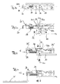
- FIG. 1 The manner of construction of the slider component is best seen from the exploded view of FIG. 1 seen. All other components of a fitting system for sliding leaf or Abstellulatel are not shown here, they do not belong to the Gleiterbauteil, take part only in a cooperating with him function that takes place during assembly of the wing. From fitting part is in the FIGS. 2 to 4 only the front, free end of an arm 10 can be seen, which carries the pin 11, which consists of a lower portion 12, a constriction portion 12a and a head portion 12b.
- This pin is rotatable in the recess 32 of FIG. 1 to store, for which he from the underside of the slider component after FIG. 2b in the local recess as a bearing opening engages while a spring arm 33 entrains in FIG. 1 is shown standing freely in a ceiling wall arranged.
- This spring arm 33 has a front pin 34 and is integrally disposed at one end of the slider member on a remnant piece of the ceiling wall.
- the top wall itself has a second remaining section opposite, which two remaining sections are pivotally connected to the base body 30 of the slider component via hinges 39 ', 39 ".
- the one-piece design thus formed is based on a lubricious material, a plastic, which allows film hinges 39 'and 39' form, in order to open and close the top wall, for the use of a preferably made of metal slide 20, which is also inserted into the main body 30 of the Gleiterbauteils.
- the slider 20 has a contour opening 22 which has a narrower portion 22a and a larger diameter portion. The asymmetry is evident with respect to a transverse plane. The longitudinal plane is aligned along the elongated slide member, ie in the direction of the spring arm 33rd
- the slider 20 as an elongated plate member has a free-standing visible edge 24 which is formed as an angled sheet metal piece. He has a downwardly projecting bend 25, which is able to engage in an elongated space 35a in the main body of the slide member and he has a securing opening 26 near the visible edge 24, which serves for explanatory locking purposes.
- Each of the receiving chambers 35a and 35b can receive a spring 35, here in FIG. 1
- This spring is drawn so that it is inserted into the receiving chamber 35 a to engage the slider 20 with its downwardly projecting bent portion 25 at the right end of the spring 35 and to move the slider to the left to bias the spring 35 and doing so after closing by the top wall (pivoting about the hinges 39 ', 39 ") with engagement of the free pin 34 in the unbalanced opening 22 with its narrower end 22a to fix the slider in the open position.
- This position is the open or ready position (also: basic position), which in the FIGS. 2a, 2b is clarified.
- the slider is ready to receive the pin 11, and has the associated bias by the spring 35, which allows him without tools, and only by engagement of the pin 11 in the recess 32 to achieve a release of this standby position to the pin in Axial direction 100 to lock in rotation.
- This rotatable lock can also be considered as a rotatable locator, in which the pin is longitudinally (axially) located and can not be removed. He remains rotatable.
- the slider 20 is blocked in longitudinal displacement direction. This blocking takes place through the elastically flexible tongue 36 ', or in reverse insertion of the slider 20 as shown FIG. 1 by the blocking lug 36 ", which then engages in the opening 26 as well as in the illustrated illustration of FIG. 3 the spring tab 36 'engages the opening 26. A return movement in the direction of -C is after FIG. 4 initially blocked.
- This position is the holding position.
- the visible edge 24 of the slider 20 is here no longer clearly visible, but became part of the body as a housing, as if they were a wall section of this.
- the holding position is mechanically closed and this closed position is visible visually, relative to the clearly visible protrusion of the visible edge 24 after FIG. 2a ,
- a release of this holding position back to the release position occurs after FIG. 4 , A tool W is for this purpose introduced into a release opening 37 in the direction D, which leads to the spring nose 36 '. This is bent back and on the visible edge 24, the slider 20, for example, be pulled out with the tool W in the direction -C. In this case, the rotatable location of the pin 11 is released, and it can be removed from the bearing opening 32 in the direction -A. This removed state corresponds again to the FIG. 2a When the slider 20 has reached the leftmost position, in which the pin 34 has intervened in the narrower portion 22a of the single-ended opening 22 and again establishes the ready position.
- a movement g takes place from the holding position F to the release position G (F -> g -> G). It arises between the FIGS. 4 and 2a , upon engagement of the tool in the direction D, bending back of the spring lug 36 'and releasing of the slider 20, which can be pulled out in the direction -C along the longitudinal direction 101, so that the visible edge 24 after FIG. 2a again is visible.
- the standby position E is characterized by the slider 20 which is spring-loaded and held by a retaining pin 34 which prevents it from being moved in the longitudinal direction 101.
- the slide is in the deflected state of this holding pin, which is arranged on the spring arm 33, longitudinally movable, in the insertion direction C, which characterizes the movement f.
- the head 12b of the pin 11 inserted into the bearing opening 32 deflects the spring arm 33 in the B direction, which follows FIG. 2b visible to the bearing opening 32 is arranged opposite.
- the holding position F is characterized by the engagement of the asymmetrical opening 22, 22a with its narrower portion around the undercut 12a of the pin. Because the pin 11 does not belong to the slider component here, the holding position F can also be characterized in that the slider 20 has no protruding projecting edge 24 more, it was rather inserted substantially into the outline of the housing 30, and the spring 35 substantially is relieved. Also, this state F can be characterized by a deflection of the spring arm 33, which by spring force in its rest position FIG. 2a pushed back, by concerns on a surface portion of the slider 20 but is prevented.
- the transition state g from the holding position to the release position G is characterized in that the spring lug 36 'is released from its locked position and can be withdrawn in the longitudinal direction 101.
- the wider portion of the opening 22 comes into alignment with the bearing opening 32, so that after pulling out the pin 11 and the spring arm standing under spring force 33 can engage with its retaining pin 34 in the narrower portion 22a of the unbalanced opening and re-lock.
- This release position G preferably again corresponds to the ready position E, which is precisely characterized in that the spring 35 is tensioned and the visible edge 24 protrudes clearly visible.
- the slider component has a top wall that does not run continuously.
- Clamps 40 ', 40 are arranged on two end sections, which are arranged and designed to achieve closing of the top wall above the main body and one positive gripping via one respective opposing edge 42', 42" of the main body.
- a respective bracket 40 ' engages over a respective counter edge 42'.
- the housing 30 In the "closed" state, the housing 30 forms a narrow, shallow shaft opening. It serves to receive and guide the longitudinally displaceable locking element 20 as a slide.
Landscapes
- Engineering & Computer Science (AREA)
- Mechanical Engineering (AREA)
- Connector Housings Or Holding Contact Members (AREA)
- Pivots And Pivotal Connections (AREA)
- Closing And Opening Devices For Wings, And Checks For Wings (AREA)
- Buckles (AREA)
Applications Claiming Priority (1)
| Application Number | Priority Date | Filing Date | Title |
|---|---|---|---|
| DE102007022398A DE102007022398B3 (de) | 2007-05-10 | 2007-05-10 | Ohne Werkzeug montierfähiges Gleiterbauteil |
Publications (4)
| Publication Number | Publication Date |
|---|---|
| EP2020476A2 true EP2020476A2 (fr) | 2009-02-04 |
| EP2020476A8 EP2020476A8 (fr) | 2009-04-22 |
| EP2020476A3 EP2020476A3 (fr) | 2014-03-12 |
| EP2020476B1 EP2020476B1 (fr) | 2015-07-29 |
Family
ID=39627741
Family Applications (1)
| Application Number | Title | Priority Date | Filing Date |
|---|---|---|---|
| EP08156004.7A Not-in-force EP2020476B1 (fr) | 2007-05-10 | 2008-05-09 | Coulisseau pouvant être assemblé sans outils |
Country Status (2)
| Country | Link |
|---|---|
| EP (1) | EP2020476B1 (fr) |
| DE (1) | DE102007022398B3 (fr) |
Cited By (2)
| Publication number | Priority date | Publication date | Assignee | Title |
|---|---|---|---|---|
| KR20190001035A (ko) * | 2017-06-26 | 2019-01-04 | 현대자동차주식회사 | 조립 편의성이 향상된 도어 힌지 어셈블리 |
| EP4575156A1 (fr) | 2023-12-22 | 2025-06-25 | Sobinco Nv | Ferrure pour fenêtre basculante |
Citations (1)
| Publication number | Priority date | Publication date | Assignee | Title |
|---|---|---|---|---|
| DE202004000610U1 (de) | 2004-01-15 | 2004-04-29 | Gretsch-Unitas GmbH Baubeschläge | Beschlag für eine Ausstell- und Kippbewegung eines Flügels eines Gebäudefensters oder einer Gebäudetür sowie Parallelschiebekipp-Fenster oder -Tür mit einem solchen Beschlag |
Family Cites Families (1)
| Publication number | Priority date | Publication date | Assignee | Title |
|---|---|---|---|---|
| DE202005015034U1 (de) * | 2005-09-22 | 2006-01-19 | Siegenia-Aubi Kg | Gleitstück für einen Beschlag |
-
2007
- 2007-05-10 DE DE102007022398A patent/DE102007022398B3/de not_active Expired - Fee Related
-
2008
- 2008-05-09 EP EP08156004.7A patent/EP2020476B1/fr not_active Not-in-force
Patent Citations (1)
| Publication number | Priority date | Publication date | Assignee | Title |
|---|---|---|---|---|
| DE202004000610U1 (de) | 2004-01-15 | 2004-04-29 | Gretsch-Unitas GmbH Baubeschläge | Beschlag für eine Ausstell- und Kippbewegung eines Flügels eines Gebäudefensters oder einer Gebäudetür sowie Parallelschiebekipp-Fenster oder -Tür mit einem solchen Beschlag |
Cited By (4)
| Publication number | Priority date | Publication date | Assignee | Title |
|---|---|---|---|---|
| KR20190001035A (ko) * | 2017-06-26 | 2019-01-04 | 현대자동차주식회사 | 조립 편의성이 향상된 도어 힌지 어셈블리 |
| KR101976931B1 (ko) | 2017-06-26 | 2019-05-09 | 현대자동차주식회사 | 조립 편의성이 향상된 도어 힌지 어셈블리 |
| EP4575156A1 (fr) | 2023-12-22 | 2025-06-25 | Sobinco Nv | Ferrure pour fenêtre basculante |
| BE1032267B1 (nl) * | 2023-12-22 | 2025-07-23 | Sobinco Fa | Beslag voor een kipbaar raam |
Also Published As
| Publication number | Publication date |
|---|---|
| EP2020476A3 (fr) | 2014-03-12 |
| EP2020476A8 (fr) | 2009-04-22 |
| DE102007022398B3 (de) | 2008-09-11 |
| EP2020476B1 (fr) | 2015-07-29 |
Similar Documents
| Publication | Publication Date | Title |
|---|---|---|
| EP3099946B1 (fr) | Moyen d'assemblage et procédé permettant d'assembler deux pièces | |
| DE102006006760B4 (de) | Vorrichtung zur Beeinflussung der Bewegung von relativ zueinander bewegbaren Möbelteilen und Schubladenführung | |
| EP1887172B1 (fr) | Dispositif destiné à verrouiller une pièce de meuble et meuble | |
| DE102015106852A1 (de) | Vorrichtung und Verfahren zum Festlegen eines Schubelementes | |
| AT506543A1 (de) | Feststellvorrichtung zum arretieren eines in oder an einem möbel bewegbar gelagerten möbelteiles | |
| EP1817983A1 (fr) | Dispositif pour influencer le mouvement des parties de meuble l'une par rapport à l'autre et une glissière pour tiroirs, ainsi qu'un procédé de fabrication d'un tel dispositif | |
| EP3291702B1 (fr) | Meuble et procédé pour fixer un tiroir | |
| DE202015104438U1 (de) | Vorrichtung zum Bewegen eines bewegbaren Möbelteils und Möbel | |
| EP4060147B1 (fr) | Dispositifs d'actionnement pour une serrure, ainsi que systèmes serrures pourvus de tels dispositifs d'actionnement | |
| EP3147435A1 (fr) | Dispositif d'arret d'extraction et meuble | |
| DE202010007430U1 (de) | Vorrichtung mit einer Anbringeinrichtung und Schublade | |
| EP2020476B1 (fr) | Coulisseau pouvant être assemblé sans outils | |
| EP2951374B1 (fr) | Pièce coulissante servant à guider une partie de meuble dans un sens de guidage sur une glissière et ferrure de meuble | |
| EP0843064B1 (fr) | Ferrure pour un fenêtre | |
| AT514167B1 (de) | Verriegelungseinrichtung | |
| DE68908097T2 (de) | Kupplungsvorrichtung zwischen Fenster und Fensterheber mit schwingenden Armen in einem Kraftfahrzeug. | |
| EP0199270B1 (fr) | Dispositif pour maintenir une porte ou une fenêtre entrouverte dans au moins une position | |
| DE3621259A1 (de) | Schliessvorrichtung | |
| DE202020104417U1 (de) | Auszugssperre | |
| EP4124709B1 (fr) | Profilé de guidage pour un verrou de tiroir, verrou de tiroir, meuble et procédé de montage d'un profilé de guidage | |
| DE102011000576A1 (de) | Schloss für eine Tür oder Dergleichen sowie Handwerkzeug für ein Schloss | |
| EP3287042B1 (fr) | Glissière de tiroir pour parties de meuble | |
| EP3239443B1 (fr) | Système de palier pour un battant oscillant contre un cadre | |
| DE3427191A1 (de) | Riegel für Schiebetüren von Möbeln | |
| EP0586334A2 (fr) | Outil à poinçonner |
Legal Events
| Date | Code | Title | Description |
|---|---|---|---|
| PUAI | Public reference made under article 153(3) epc to a published international application that has entered the european phase |
Free format text: ORIGINAL CODE: 0009012 |
|
| AK | Designated contracting states |
Kind code of ref document: A2 Designated state(s): AT BE BG CH CY CZ DE DK EE ES FI FR GB GR HR HU IE IS IT LI LT LU LV MC MT NL NO PL PT RO SE SI SK TR |
|
| AX | Request for extension of the european patent |
Extension state: AL BA MK RS |
|
| RAP1 | Party data changed (applicant data changed or rights of an application transferred) |
Owner name: HAUTAU GMBH |
|
| RIC1 | Information provided on ipc code assigned before grant |
Ipc: E05D 7/10 20060101AFI20131011BHEP Ipc: E05D 15/52 20060101ALI20131011BHEP |
|
| PUAL | Search report despatched |
Free format text: ORIGINAL CODE: 0009013 |
|
| AK | Designated contracting states |
Kind code of ref document: A3 Designated state(s): AT BE BG CH CY CZ DE DK EE ES FI FR GB GR HR HU IE IS IT LI LT LU LV MC MT NL NO PL PT RO SE SI SK TR |
|
| AX | Request for extension of the european patent |
Extension state: AL BA MK RS |
|
| RIC1 | Information provided on ipc code assigned before grant |
Ipc: E05D 15/52 20060101ALI20140131BHEP Ipc: E05D 7/10 20060101AFI20140131BHEP |
|
| 17P | Request for examination filed |
Effective date: 20140711 |
|
| RBV | Designated contracting states (corrected) |
Designated state(s): AT BE BG CH CY CZ DE DK EE ES FI FR GB GR HR HU IE IS IT LI LT LU LV MC MT NL NO PL PT RO SE SI SK TR |
|
| AKX | Designation fees paid |
Designated state(s): AT BE BG CH CY CZ DE DK EE ES FI FR GB GR HR HU IE IS IT LI LT LU LV MC MT NL NO PL PT RO SE SI SK TR |
|
| REG | Reference to a national code |
Ref country code: DE Ref legal event code: R079 Ref document number: 502008013189 Country of ref document: DE Free format text: PREVIOUS MAIN CLASS: E05D0015000000 Ipc: E05D0007100000 |
|
| GRAP | Despatch of communication of intention to grant a patent |
Free format text: ORIGINAL CODE: EPIDOSNIGR1 |
|
| RIC1 | Information provided on ipc code assigned before grant |
Ipc: E05D 7/10 20060101AFI20150116BHEP Ipc: E05D 15/52 20060101ALI20150116BHEP |
|
| INTG | Intention to grant announced |
Effective date: 20150205 |
|
| GRAS | Grant fee paid |
Free format text: ORIGINAL CODE: EPIDOSNIGR3 |
|
| GRAA | (expected) grant |
Free format text: ORIGINAL CODE: 0009210 |
|
| AK | Designated contracting states |
Kind code of ref document: B1 Designated state(s): AT BE BG CH CY CZ DE DK EE ES FI FR GB GR HR HU IE IS IT LI LT LU LV MC MT NL NO PL PT RO SE SI SK TR |
|
| REG | Reference to a national code |
Ref country code: GB Ref legal event code: FG4D Free format text: NOT ENGLISH |
|
| REG | Reference to a national code |
Ref country code: CH Ref legal event code: EP |
|
| REG | Reference to a national code |
Ref country code: AT Ref legal event code: REF Ref document number: 739437 Country of ref document: AT Kind code of ref document: T Effective date: 20150815 |
|
| REG | Reference to a national code |
Ref country code: IE Ref legal event code: FG4D Free format text: LANGUAGE OF EP DOCUMENT: GERMAN |
|
| REG | Reference to a national code |
Ref country code: DE Ref legal event code: R096 Ref document number: 502008013189 Country of ref document: DE |
|
| REG | Reference to a national code |
Ref country code: LT Ref legal event code: MG4D |
|
| REG | Reference to a national code |
Ref country code: NL Ref legal event code: MP Effective date: 20150729 |
|
| PG25 | Lapsed in a contracting state [announced via postgrant information from national office to epo] |
Ref country code: NO Free format text: LAPSE BECAUSE OF FAILURE TO SUBMIT A TRANSLATION OF THE DESCRIPTION OR TO PAY THE FEE WITHIN THE PRESCRIBED TIME-LIMIT Effective date: 20151029 Ref country code: LV Free format text: LAPSE BECAUSE OF FAILURE TO SUBMIT A TRANSLATION OF THE DESCRIPTION OR TO PAY THE FEE WITHIN THE PRESCRIBED TIME-LIMIT Effective date: 20150729 Ref country code: LT Free format text: LAPSE BECAUSE OF FAILURE TO SUBMIT A TRANSLATION OF THE DESCRIPTION OR TO PAY THE FEE WITHIN THE PRESCRIBED TIME-LIMIT Effective date: 20150729 Ref country code: FI Free format text: LAPSE BECAUSE OF FAILURE TO SUBMIT A TRANSLATION OF THE DESCRIPTION OR TO PAY THE FEE WITHIN THE PRESCRIBED TIME-LIMIT Effective date: 20150729 Ref country code: GR Free format text: LAPSE BECAUSE OF FAILURE TO SUBMIT A TRANSLATION OF THE DESCRIPTION OR TO PAY THE FEE WITHIN THE PRESCRIBED TIME-LIMIT Effective date: 20151030 |
|
| PG25 | Lapsed in a contracting state [announced via postgrant information from national office to epo] |
Ref country code: IS Free format text: LAPSE BECAUSE OF FAILURE TO SUBMIT A TRANSLATION OF THE DESCRIPTION OR TO PAY THE FEE WITHIN THE PRESCRIBED TIME-LIMIT Effective date: 20151129 Ref country code: SE Free format text: LAPSE BECAUSE OF FAILURE TO SUBMIT A TRANSLATION OF THE DESCRIPTION OR TO PAY THE FEE WITHIN THE PRESCRIBED TIME-LIMIT Effective date: 20150729 Ref country code: HR Free format text: LAPSE BECAUSE OF FAILURE TO SUBMIT A TRANSLATION OF THE DESCRIPTION OR TO PAY THE FEE WITHIN THE PRESCRIBED TIME-LIMIT Effective date: 20150729 Ref country code: PT Free format text: LAPSE BECAUSE OF FAILURE TO SUBMIT A TRANSLATION OF THE DESCRIPTION OR TO PAY THE FEE WITHIN THE PRESCRIBED TIME-LIMIT Effective date: 20151130 Ref country code: PL Free format text: LAPSE BECAUSE OF FAILURE TO SUBMIT A TRANSLATION OF THE DESCRIPTION OR TO PAY THE FEE WITHIN THE PRESCRIBED TIME-LIMIT Effective date: 20150729 Ref country code: ES Free format text: LAPSE BECAUSE OF FAILURE TO SUBMIT A TRANSLATION OF THE DESCRIPTION OR TO PAY THE FEE WITHIN THE PRESCRIBED TIME-LIMIT Effective date: 20150729 |
|
| PG25 | Lapsed in a contracting state [announced via postgrant information from national office to epo] |
Ref country code: NL Free format text: LAPSE BECAUSE OF FAILURE TO SUBMIT A TRANSLATION OF THE DESCRIPTION OR TO PAY THE FEE WITHIN THE PRESCRIBED TIME-LIMIT Effective date: 20150729 |
|
| PG25 | Lapsed in a contracting state [announced via postgrant information from national office to epo] |
Ref country code: EE Free format text: LAPSE BECAUSE OF FAILURE TO SUBMIT A TRANSLATION OF THE DESCRIPTION OR TO PAY THE FEE WITHIN THE PRESCRIBED TIME-LIMIT Effective date: 20150729 Ref country code: DK Free format text: LAPSE BECAUSE OF FAILURE TO SUBMIT A TRANSLATION OF THE DESCRIPTION OR TO PAY THE FEE WITHIN THE PRESCRIBED TIME-LIMIT Effective date: 20150729 Ref country code: CZ Free format text: LAPSE BECAUSE OF FAILURE TO SUBMIT A TRANSLATION OF THE DESCRIPTION OR TO PAY THE FEE WITHIN THE PRESCRIBED TIME-LIMIT Effective date: 20150729 Ref country code: SK Free format text: LAPSE BECAUSE OF FAILURE TO SUBMIT A TRANSLATION OF THE DESCRIPTION OR TO PAY THE FEE WITHIN THE PRESCRIBED TIME-LIMIT Effective date: 20150729 |
|
| REG | Reference to a national code |
Ref country code: DE Ref legal event code: R097 Ref document number: 502008013189 Country of ref document: DE |
|
| PG25 | Lapsed in a contracting state [announced via postgrant information from national office to epo] |
Ref country code: RO Free format text: LAPSE BECAUSE OF FAILURE TO SUBMIT A TRANSLATION OF THE DESCRIPTION OR TO PAY THE FEE WITHIN THE PRESCRIBED TIME-LIMIT Effective date: 20150729 |
|
| PLBE | No opposition filed within time limit |
Free format text: ORIGINAL CODE: 0009261 |
|
| STAA | Information on the status of an ep patent application or granted ep patent |
Free format text: STATUS: NO OPPOSITION FILED WITHIN TIME LIMIT |
|
| 26N | No opposition filed |
Effective date: 20160502 |
|
| PG25 | Lapsed in a contracting state [announced via postgrant information from national office to epo] |
Ref country code: BE Free format text: LAPSE BECAUSE OF NON-PAYMENT OF DUE FEES Effective date: 20160531 Ref country code: SI Free format text: LAPSE BECAUSE OF FAILURE TO SUBMIT A TRANSLATION OF THE DESCRIPTION OR TO PAY THE FEE WITHIN THE PRESCRIBED TIME-LIMIT Effective date: 20150729 |
|
| PG25 | Lapsed in a contracting state [announced via postgrant information from national office to epo] |
Ref country code: LU Free format text: LAPSE BECAUSE OF FAILURE TO SUBMIT A TRANSLATION OF THE DESCRIPTION OR TO PAY THE FEE WITHIN THE PRESCRIBED TIME-LIMIT Effective date: 20160509 |
|
| REG | Reference to a national code |
Ref country code: CH Ref legal event code: PL |
|
| GBPC | Gb: european patent ceased through non-payment of renewal fee |
Effective date: 20160509 |
|
| PG25 | Lapsed in a contracting state [announced via postgrant information from national office to epo] |
Ref country code: LI Free format text: LAPSE BECAUSE OF NON-PAYMENT OF DUE FEES Effective date: 20160531 Ref country code: CH Free format text: LAPSE BECAUSE OF NON-PAYMENT OF DUE FEES Effective date: 20160531 |
|
| REG | Reference to a national code |
Ref country code: IE Ref legal event code: MM4A |
|
| REG | Reference to a national code |
Ref country code: FR Ref legal event code: ST Effective date: 20170131 |
|
| PG25 | Lapsed in a contracting state [announced via postgrant information from national office to epo] |
Ref country code: FR Free format text: LAPSE BECAUSE OF NON-PAYMENT OF DUE FEES Effective date: 20160531 |
|
| PG25 | Lapsed in a contracting state [announced via postgrant information from national office to epo] |
Ref country code: IE Free format text: LAPSE BECAUSE OF NON-PAYMENT OF DUE FEES Effective date: 20160509 Ref country code: GB Free format text: LAPSE BECAUSE OF NON-PAYMENT OF DUE FEES Effective date: 20160509 |
|
| PGFP | Annual fee paid to national office [announced via postgrant information from national office to epo] |
Ref country code: IT Payment date: 20170524 Year of fee payment: 10 Ref country code: AT Payment date: 20170519 Year of fee payment: 10 |
|
| PG25 | Lapsed in a contracting state [announced via postgrant information from national office to epo] |
Ref country code: HU Free format text: LAPSE BECAUSE OF FAILURE TO SUBMIT A TRANSLATION OF THE DESCRIPTION OR TO PAY THE FEE WITHIN THE PRESCRIBED TIME-LIMIT; INVALID AB INITIO Effective date: 20080509 Ref country code: CY Free format text: LAPSE BECAUSE OF FAILURE TO SUBMIT A TRANSLATION OF THE DESCRIPTION OR TO PAY THE FEE WITHIN THE PRESCRIBED TIME-LIMIT Effective date: 20150729 |
|
| PG25 | Lapsed in a contracting state [announced via postgrant information from national office to epo] |
Ref country code: MC Free format text: LAPSE BECAUSE OF FAILURE TO SUBMIT A TRANSLATION OF THE DESCRIPTION OR TO PAY THE FEE WITHIN THE PRESCRIBED TIME-LIMIT Effective date: 20150729 Ref country code: MT Free format text: LAPSE BECAUSE OF FAILURE TO SUBMIT A TRANSLATION OF THE DESCRIPTION OR TO PAY THE FEE WITHIN THE PRESCRIBED TIME-LIMIT Effective date: 20150729 |
|
| PG25 | Lapsed in a contracting state [announced via postgrant information from national office to epo] |
Ref country code: BG Free format text: LAPSE BECAUSE OF FAILURE TO SUBMIT A TRANSLATION OF THE DESCRIPTION OR TO PAY THE FEE WITHIN THE PRESCRIBED TIME-LIMIT Effective date: 20150729 |
|
| REG | Reference to a national code |
Ref country code: AT Ref legal event code: MM01 Ref document number: 739437 Country of ref document: AT Kind code of ref document: T Effective date: 20180509 |
|
| PG25 | Lapsed in a contracting state [announced via postgrant information from national office to epo] |
Ref country code: AT Free format text: LAPSE BECAUSE OF NON-PAYMENT OF DUE FEES Effective date: 20180509 |
|
| PG25 | Lapsed in a contracting state [announced via postgrant information from national office to epo] |
Ref country code: IT Free format text: LAPSE BECAUSE OF NON-PAYMENT OF DUE FEES Effective date: 20180509 |
|
| PGFP | Annual fee paid to national office [announced via postgrant information from national office to epo] |
Ref country code: DE Payment date: 20190524 Year of fee payment: 12 |
|
| PGFP | Annual fee paid to national office [announced via postgrant information from national office to epo] |
Ref country code: TR Payment date: 20190429 Year of fee payment: 12 |
|
| REG | Reference to a national code |
Ref country code: DE Ref legal event code: R119 Ref document number: 502008013189 Country of ref document: DE |
|
| PG25 | Lapsed in a contracting state [announced via postgrant information from national office to epo] |
Ref country code: DE Free format text: LAPSE BECAUSE OF NON-PAYMENT OF DUE FEES Effective date: 20201201 |
|
| PG25 | Lapsed in a contracting state [announced via postgrant information from national office to epo] |
Ref country code: TR Free format text: LAPSE BECAUSE OF NON-PAYMENT OF DUE FEES Effective date: 20200509 |