EP2020501A2 - Boîtier d'échangeur thermique, échangeur thermique ou composant doté d'un ou plusieurs échangeurs thermiques, système de récupération des gaz d'échappement, système d'alimentation en air de suralimentation et utilisation de l'échangeur thermique - Google Patents
Boîtier d'échangeur thermique, échangeur thermique ou composant doté d'un ou plusieurs échangeurs thermiques, système de récupération des gaz d'échappement, système d'alimentation en air de suralimentation et utilisation de l'échangeur thermique Download PDFInfo
- Publication number
- EP2020501A2 EP2020501A2 EP08012978A EP08012978A EP2020501A2 EP 2020501 A2 EP2020501 A2 EP 2020501A2 EP 08012978 A EP08012978 A EP 08012978A EP 08012978 A EP08012978 A EP 08012978A EP 2020501 A2 EP2020501 A2 EP 2020501A2
- Authority
- EP
- European Patent Office
- Prior art keywords
- heat exchanger
- fluid
- housing
- housing body
- exhaust gas
- Prior art date
- Legal status (The legal status is an assumption and is not a legal conclusion. Google has not performed a legal analysis and makes no representation as to the accuracy of the status listed.)
- Granted
Links
- 238000004064 recycling Methods 0.000 title 1
- 239000012530 fluid Substances 0.000 claims abstract description 71
- 238000001816 cooling Methods 0.000 claims abstract description 9
- XAGFODPZIPBFFR-UHFFFAOYSA-N aluminium Chemical compound [Al] XAGFODPZIPBFFR-UHFFFAOYSA-N 0.000 claims abstract description 4
- 229910052782 aluminium Inorganic materials 0.000 claims abstract description 4
- 238000005495 investment casting Methods 0.000 claims abstract description 4
- 238000004512 die casting Methods 0.000 claims abstract 2
- 239000002826 coolant Substances 0.000 claims description 12
- 238000002485 combustion reaction Methods 0.000 claims description 8
- 239000011324 bead Substances 0.000 claims description 4
- 229910000831 Steel Chemical group 0.000 claims description 3
- 239000010959 steel Chemical group 0.000 claims description 3
- 238000005266 casting Methods 0.000 claims description 2
- 230000010412 perfusion Effects 0.000 abstract 2
- 238000001746 injection moulding Methods 0.000 abstract 1
- 239000007789 gas Substances 0.000 description 29
- 238000011161 development Methods 0.000 description 10
- 230000018109 developmental process Effects 0.000 description 10
- 238000004519 manufacturing process Methods 0.000 description 4
- MWUXSHHQAYIFBG-UHFFFAOYSA-N Nitric oxide Chemical compound O=[N] MWUXSHHQAYIFBG-UHFFFAOYSA-N 0.000 description 3
- 238000005192 partition Methods 0.000 description 3
- 238000002347 injection Methods 0.000 description 2
- 239000007924 injection Substances 0.000 description 2
- 239000007788 liquid Substances 0.000 description 2
- 230000004048 modification Effects 0.000 description 2
- 238000012986 modification Methods 0.000 description 2
- XLYOFNOQVPJJNP-UHFFFAOYSA-N water Substances O XLYOFNOQVPJJNP-UHFFFAOYSA-N 0.000 description 2
- 238000007792 addition Methods 0.000 description 1
- 230000001419 dependent effect Effects 0.000 description 1
- 238000007599 discharging Methods 0.000 description 1
- 239000003344 environmental pollutant Substances 0.000 description 1
- 230000010354 integration Effects 0.000 description 1
- 239000000463 material Substances 0.000 description 1
- 239000013618 particulate matter Substances 0.000 description 1
- 231100000719 pollutant Toxicity 0.000 description 1
- 230000003014 reinforcing effect Effects 0.000 description 1
- 238000000926 separation method Methods 0.000 description 1
Images
Classifications
-
- F—MECHANICAL ENGINEERING; LIGHTING; HEATING; WEAPONS; BLASTING
- F02—COMBUSTION ENGINES; HOT-GAS OR COMBUSTION-PRODUCT ENGINE PLANTS
- F02B—INTERNAL-COMBUSTION PISTON ENGINES; COMBUSTION ENGINES IN GENERAL
- F02B29/00—Engines characterised by provision for charging or scavenging not provided for in groups F02B25/00, F02B27/00 or F02B33/00 - F02B39/00; Details thereof
- F02B29/04—Cooling of air intake supply
- F02B29/045—Constructional details of the heat exchangers, e.g. pipes, plates, ribs, insulation, materials, or manufacturing and assembly
- F02B29/0462—Liquid cooled heat exchangers
-
- F—MECHANICAL ENGINEERING; LIGHTING; HEATING; WEAPONS; BLASTING
- F02—COMBUSTION ENGINES; HOT-GAS OR COMBUSTION-PRODUCT ENGINE PLANTS
- F02M—SUPPLYING COMBUSTION ENGINES IN GENERAL WITH COMBUSTIBLE MIXTURES OR CONSTITUENTS THEREOF
- F02M26/00—Engine-pertinent apparatus for adding exhaust gases to combustion-air, main fuel or fuel-air mixture, e.g. by exhaust gas recirculation [EGR] systems
- F02M26/13—Arrangement or layout of EGR passages, e.g. in relation to specific engine parts or for incorporation of accessories
- F02M26/22—Arrangement or layout of EGR passages, e.g. in relation to specific engine parts or for incorporation of accessories with coolers in the recirculation passage
- F02M26/23—Layout, e.g. schematics
- F02M26/25—Layout, e.g. schematics with coolers having bypasses
-
- F—MECHANICAL ENGINEERING; LIGHTING; HEATING; WEAPONS; BLASTING
- F02—COMBUSTION ENGINES; HOT-GAS OR COMBUSTION-PRODUCT ENGINE PLANTS
- F02M—SUPPLYING COMBUSTION ENGINES IN GENERAL WITH COMBUSTIBLE MIXTURES OR CONSTITUENTS THEREOF
- F02M26/00—Engine-pertinent apparatus for adding exhaust gases to combustion-air, main fuel or fuel-air mixture, e.g. by exhaust gas recirculation [EGR] systems
- F02M26/13—Arrangement or layout of EGR passages, e.g. in relation to specific engine parts or for incorporation of accessories
- F02M26/22—Arrangement or layout of EGR passages, e.g. in relation to specific engine parts or for incorporation of accessories with coolers in the recirculation passage
- F02M26/29—Constructional details of the coolers, e.g. pipes, plates, ribs, insulation or materials
- F02M26/32—Liquid-cooled heat exchangers
-
- F—MECHANICAL ENGINEERING; LIGHTING; HEATING; WEAPONS; BLASTING
- F28—HEAT EXCHANGE IN GENERAL
- F28F—DETAILS OF HEAT-EXCHANGE AND HEAT-TRANSFER APPARATUS, OF GENERAL APPLICATION
- F28F9/00—Casings; Header boxes; Auxiliary supports for elements; Auxiliary members within casings
-
- F—MECHANICAL ENGINEERING; LIGHTING; HEATING; WEAPONS; BLASTING
- F28—HEAT EXCHANGE IN GENERAL
- F28F—DETAILS OF HEAT-EXCHANGE AND HEAT-TRANSFER APPARATUS, OF GENERAL APPLICATION
- F28F2250/00—Arrangements for modifying the flow of the heat exchange media, e.g. flow guiding means; Particular flow patterns
- F28F2250/06—Derivation channels, e.g. bypass
-
- Y—GENERAL TAGGING OF NEW TECHNOLOGICAL DEVELOPMENTS; GENERAL TAGGING OF CROSS-SECTIONAL TECHNOLOGIES SPANNING OVER SEVERAL SECTIONS OF THE IPC; TECHNICAL SUBJECTS COVERED BY FORMER USPC CROSS-REFERENCE ART COLLECTIONS [XRACs] AND DIGESTS
- Y02—TECHNOLOGIES OR APPLICATIONS FOR MITIGATION OR ADAPTATION AGAINST CLIMATE CHANGE
- Y02T—CLIMATE CHANGE MITIGATION TECHNOLOGIES RELATED TO TRANSPORTATION
- Y02T10/00—Road transport of goods or passengers
- Y02T10/10—Internal combustion engine [ICE] based vehicles
- Y02T10/12—Improving ICE efficiencies
Definitions
- the invention relates to a heat exchanger housing for at least one heat exchanger for heat exchange between a first fluid and a second fluid. Furthermore, the invention relates to a heat exchanger or a structural unit with one or more heat exchangers for heat exchange between a first fluid and a second fluid. The invention also relates to an exhaust gas recirculation system, a charge air supply system and a use of the heat exchanger or the structural unit.
- Exhaust gas recirculation or charge air supply in particular with cooled exhaust gas and / or charge air, is used in current vehicles due to legal provisions in order to reduce particulate matter and pollutants, in particular nitrogen oxide emissions.
- the requirements for the exhaust gas pollution control and the exhaust gas mass flows to be managed increase, on the other hand, such systems and in particular the necessary heat exchanger developments are highly cost-driven.
- a heat exchanger is basically used for heat exchange between a first fluid, in particular an exhaust gas in the case of an exhaust gas cooler or a charge air in the case of a charge air cooler, and a second fluid, in particular a coolant, for example a water-based coolant or other liquid or gaseous coolant.
- a first fluid in particular an exhaust gas in the case of an exhaust gas cooler or a charge air in the case of a charge air cooler
- a second fluid in particular a coolant, for example a water-based coolant or other liquid or gaseous coolant.
- exhaust gas coolers are optionally removed with a bypass tube to achieve the operating temperature of an internal combustion engine faster.
- a bypass channel can be closed, for example, via a flap as soon as the operating temperature is reached on the internal combustion engine and a heat exchanger is provided for receiving the cooling operation.
- DE 10 203 003 A1 discloses a single stage heat exchanger system with an integrated bypass channel and by-pass damper.
- bypass duct in the form of a bypass pipe has to be manufactured separately from the module or the system and casked into a heat exchanger housing and subsequently with a suitable connection part of the heat exchanger, for example a bottom at the block of the heat exchanger, be welded.
- the invention begins, the object of which is to provide a device, in particular a heat exchanger housing and a heat exchanger, in which the integration of a bypass channel is realized in a simpler and more cost-effective manner.
- a heat exchanger housing of the type mentioned which according to the invention comprises a housing body with a flow-through from the second fluid and for receiving a number of the first fluid flow-through flow channels designed chamber; a bypass channel designed to flow through the first fluid; wherein the chamber and the bypass channel are formed integrally with the housing body.
- the concept of the invention provides that the bypass channel is integrally integrated in the heat exchanger housing. This has the advantage that the bypass channel and the housing can be produced in a particularly simple and cost-saving manner in a single production step. This eliminates the cost-generating and sometimes expensive separate manufacturing steps for a bypass pipe or, the Kasset réelle a bypass pipe in a housing.
- the object is achieved by the invention by means of a heat exchanger or a structural unit with one or more heat exchangers of the type mentioned, which comprises: a block for separate and heat exchanging guidance of the first and second fluid, which block a heat exchanger housing with integrated bypass channel according to the concept of the invention and has a recorded in the heat exchanger housing number of the first fluid permeable flow channels.
- the first fluid is formed as an exhaust gas and / or a charge air.
- a heat exchanger may preferably be formed as an exhaust gas heat exchanger and / or charge air heat exchanger.
- the second fluid is formed in the form of a coolant, for example a water-based coolant or other liquid coolant. Also suitable may be a gaseous coolant.
- the concept of the invention also leads to an exhaust gas recirculation system for an internal combustion engine, comprising an exhaust gas recirculation, a compressor and a heat exchanger of the aforementioned type in the form of an exhaust gas heat exchanger, in particular an exhaust gas cooler.
- the concept of the invention also leads to a charge air supply system for an internal combustion engine, comprising a charge air intake, an air filter, a compressor and a heat exchanger of the aforementioned type in the form of a charge air heat exchanger, in particular intercooler.
- the invention leads to a use of the heat exchanger or the assembly of the aforementioned type for an internal combustion engine, in particular a diesel engine or gasoline engine of a motor vehicle.
- the bypass channel is the only bypass channel and / or extends along the entire length of an elongated extension of the housing body.
- the bypass channel can have practically the same length as the chamber.
- the bypass channel can be designed correspondingly in cross-section of an application, in particular rectangular, oval or semi-oval.
- the chamber for receiving the flow channels of two heat exchangers in particular a high-temperature heat exchanger and a low-temperature heat exchanger is formed.
- this is done on an inner side of the housing body a socket formed integrally with the housing body.
- the base is arranged transversely to the elongate extent of the housing body.
- it has a trapezoidal cross-section.
- the flow channels of a first heat exchanger and a second heat exchanger can be arranged in a marked by the base first part or second part of the chamber.
- a cross-sectionally trapezoidal base allows a practically self-aligning arrangement of the flow channels.
- the heat exchanger housing has at least one connection part, preferably an input-side and an output-side connection part, for connecting at least one first fluid connection for the first fluid.
- the connection part is formed integrally with the housing body.
- a development of the heat exchanger advantageously provides that a first fluid connection with the flow channels is arranged fluidly connected to the connection part of the housing body.
- the first fluid connection can be formed, for example, as a box and / or a box lid, preferably in the form of a diffuser.
- An entrance-side fluid port may be formed as an entrance diffuser and / or exit-side fluid port as an exit diffuser.
- bypass control device in the heat exchanger for adjusting the exhaust gas passage through the at least one heat exchanger.
- the control device can be integrated in a particularly advantageous manner in the fluid connection.
- a bypass flap may be integrated in a diffuser.
- Other possible advantageous control devices may additionally or alternatively be in the form of a valve device, for example a controllable valve.
- connection part of the heat exchanger housing may be formed in a particularly preferred development to - on the one hand - in particular Housing inside, a block terminating element for separating the chamber and a first fluid port for the first fluid to be arranged on the connection part of the housing body and / or - on the other hand - in particular housing outside space side, to arrange the fluid connection to the connection part.
- the block closure element for example in the form of a bottom, is preferably provided with one or more passage openings for the flow channels.
- connection part As a flange.
- a bead which preferably serves to receive a seal. It has been found that thereby a particularly advantageous and fluid-tight separation of a first fluid in the flow channels or a first fluid port and a second fluid in the chamber is possible.
- the heat exchanger housing also has a second fluid connection for the second fluid, wherein the at least one second fluid connection, for example a fluid inlet and a fluid outlet connection, is formed integrally with the housing body.
- a second fluid connection is formed in the form of a nozzle. This has proved to be particularly suitable for connecting a conduit for the second fluid.
- the heat exchanger housing is particularly advantageously provided with a connection part for connecting at least the first fluid connection for the first fluid and a second fluid connection for the second fluid, wherein the first and second fluid connections are formed integrally with the housing.
- a connection part has an inlet border for the first fluid and this inlet border and a further inlet border of the bypass channel are formed at the same point of an elongated extent of the housing body.
- the inlet border in the connection part can be formed as a common part of the housing body.
- a connection part - for example in the form of an eight-shaped flange - may have a first opening to the chamber and a second opening to the bypass channel.
- the connection part may also be formed at the same point of an elongated extension of the housing body, likewise with a combination of the aforementioned further developments, and a second fluid connection.
- the second fluid connection to the connection part is preferably formed as a common part of the housing body.
- the heat exchanger housing is provided with a number of cooling fins formed integrally with the housing body. Cooling ribs may in particular extend circumferentially and / or along an elongated extent of the housing body. Depending on requirements, the cooling fins can for simplicity run through the bypass channel and the chamber part of the housing through. In principle, the cooling fins can be designed according to requirements and the amount of heat to be dissipated or additionally or alternatively designed as reinforcing ribs.
- the design of the heat exchanger housing as an aluminum casting is particularly preferred.
- the heat exchanger housing can also be designed as a steel part or as a plastic part - preferably as a precision casting or injection molded part.
- a block closure element for separating the chamber and a first fluid connection for the first fluid is arranged on a connection part (21, 31) of the housing body (10), wherein the block closure element, in particular, a floor is provided with one or more passage openings for the flow channels.
- a heat exchanger or structural unit comprising a bypass control device for adjusting the exhaust gas flow through the at least one heat exchanger, in particular a valve device and / or bypass valve, and / or a valve, in particular an exhaust gas recirculation valve.
- a control device is integrated in the first, preferably input-side, fluid connection, in particular a bypass flap is integrated in a diffuser.
- a heat exchanger or structural unit comprising a high-temperature heat exchanger and / or low-temperature heat exchanger, wherein the low-temperature heat exchanger is arranged downstream of the high-temperature heat exchanger.
- an exhaust gas recirculation system for an internal combustion engine comprising an exhaust gas recirculation, a compressor and characterized by a heat exchanger or structural unit in the form of an exhaust gas heat exchanger, in particular -Kühlers.
- the use of the heat exchanger or the assembly for an internal combustion engine, in particular a diesel engine or gasoline engine, a motor vehicle.
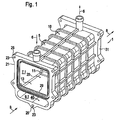
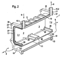
- Fig. 1 and Fig. 2 show a heat exchanger housing 1 for the arrangement of the flow-through of exhaust gas flow passages of a high-temperature heat exchanger 2, not shown, and the flow-through of exhaust gas flow channels of a non-illustrated low-temperature heat exchanger 3 respectively in a first part 20 and a second part 30 of a chamber of the housing body 10 of the heat exchanger housing.
- This housing for the parts 20, 30 of the chamber is marked by a cross-sectionally trapezoidal and integrally formed with the housing body 10 base 11, wherein the trapezoidal design of the base 11 for self-aligning the high-temperature heat exchanger 2 and the low-temperature heat exchanger 3 in the parts 20, 30 of Chamber serves.
- the heat exchanger housing 1 also has a bypass channel 40, which is separated by a partition 13 from the parts 20, 30 of the chamber.
- the base 11 is formed integrally with the partition wall 13.
- the bypass channel 40 designed for the passage of exhaust gas and the parts 20, 30 of the chamber are formed integrally with the housing body 10.
- the parts 20, 30 of the chamber and the bypass channel 40 are bounded by a wall 5 of the housing body 10, wherein in a section transverse to the elongated extension of the housing 1, the wall 5 and the partition 13 assume an octagonal shape, each one Forming the input-side and output-side first opening 7.1 or 7.2 to the first part 20 and second part 30 of the chamber and an input-side second opening 9.1 and 9.2 to the bypass channel 40.
- the heat exchanger housing 1 is thus designed to flow through with exhaust gas 8 through the openings 7.1, 7.2 and / or 9.1, 9.2.
- integrally formed with the housing body 10 is an inlet-side second fluid port 15.1 and an outlet-side second fluid port 15.2 for supplying or discharging a coolant 6, each in the form of a connecting piece.
- FIG. 1 and Fig. 2 described embodiment of a heat exchanger housing an inlet border 17 of a first part 20 and a second part 30 of the chamber and an inlet border 19 of the bypass channel 40 and a second fluid port 15.1 and 15.2 as a common connecting part 21 and 31 of the housing body 10.
- the connecting part 21 and the output-side connecting part 31 are each in the form of an eight-shaped flange, which are provided on the corner with a part 20, 30 of the chamber with eyes 25 having fastening openings 23, on the outside of the housing a box cover designed as a diffuser for the supply or delivery To install exhaust gas outlet.
- Another provided with a mounting opening 23 eye 25 on the connecting part 21 and 31 is located centrally below the bypass channel 40.
- connecting part 21, 31 is provided with a bead 27 for receiving a seal in order to each seal a diffuser on the connecting part 21, 31 and thus to allow a seal carried in the parts 20, 30 to the exhaust gas.
- a block closure element in the form of a bottom can be fixed in a manner not shown.
- Such a bottom is provided with a plurality of passage openings for receiving the flow channels of the high-temperature heat exchanger 2 and the low-temperature heat exchanger 3.
- Additional bottoms of the high-temperature heat exchanger 2 or low-temperature heat exchanger 3 can be arranged on the base 11.
- a housing body 1 is provided, with a chamber designed for the flow of coolant and for receiving a number of flow channels through which exhaust gas can flow as well as a bypass duct 40 designed for flow with exhaust gas, both in one piece are formed with the housing body 10.
- the housing body 10 may be integrally formed according to the embodiment described above with connecting parts 21, 31, the corresponding edges 17, 19 of the chamber and the bypass channel 40 and connecting pieces 15.1, 15.2 combine for the coolant and further advantageous for housing a diffuser on the outside of the housing and a bottom housing inside are formed.
- the heat exchanger housing in a manufacturing step, in this case in the context of a cast aluminum, can be produced.
- the heat exchanger housing may also be manufactured as a steel investment casting or as a plastic injection molded part.
Landscapes
- Engineering & Computer Science (AREA)
- Mechanical Engineering (AREA)
- General Engineering & Computer Science (AREA)
- Chemical & Material Sciences (AREA)
- Combustion & Propulsion (AREA)
- Physics & Mathematics (AREA)
- Thermal Sciences (AREA)
- Exhaust-Gas Circulating Devices (AREA)
- Heat-Exchange Devices With Radiators And Conduit Assemblies (AREA)
Applications Claiming Priority (1)
| Application Number | Priority Date | Filing Date | Title |
|---|---|---|---|
| DE102007036301A DE102007036301A1 (de) | 2007-07-31 | 2007-07-31 | Wärmetauschergehäuse, Wärmetauscher oder Baueinheit mit einem oder mehreren Wärmetauschern, Abgasrückführsystem, Ladeluftzuführsystem und Verwendung des Wärmetauschers |
Publications (3)
| Publication Number | Publication Date |
|---|---|
| EP2020501A2 true EP2020501A2 (fr) | 2009-02-04 |
| EP2020501A3 EP2020501A3 (fr) | 2014-01-22 |
| EP2020501B1 EP2020501B1 (fr) | 2018-02-21 |
Family
ID=39791150
Family Applications (1)
| Application Number | Title | Priority Date | Filing Date |
|---|---|---|---|
| EP08012978.6A Ceased EP2020501B1 (fr) | 2007-07-31 | 2008-07-18 | Boîtier d'échangeur thermique, échangeur thermique ou composant doté d'un ou plusieurs échangeurs thermiques, système de récupération des gaz d'échappement, système d'alimentation en air de suralimentation et utilisation de l'échangeur thermique |
Country Status (3)
| Country | Link |
|---|---|
| US (1) | US8596342B2 (fr) |
| EP (1) | EP2020501B1 (fr) |
| DE (1) | DE102007036301A1 (fr) |
Cited By (2)
| Publication number | Priority date | Publication date | Assignee | Title |
|---|---|---|---|---|
| DE102014222158A1 (de) * | 2014-10-30 | 2016-05-04 | Mahle International Gmbh | Abgaswärmeübertrager |
| EP3217006A1 (fr) * | 2016-03-09 | 2017-09-13 | PSA Automobiles SA | Moteur thermique à système de recirculation des gaz d'échappement |
Families Citing this family (12)
| Publication number | Priority date | Publication date | Assignee | Title |
|---|---|---|---|---|
| US20100224173A1 (en) * | 2009-03-09 | 2010-09-09 | Herve Palanchon | Heat Exchanger with Cast Housing and Method of Making Same |
| DE102009026818A1 (de) * | 2009-06-08 | 2010-12-09 | Deere & Company, Moline | Abgasnachbehandlungssystem |
| EP2463490B1 (fr) * | 2010-12-10 | 2015-09-09 | Perkins Engines Company Limited | Améliorations de ou liées à des refroidisseurs de gaz pour moteurs à combustion interne |
| DE102011011117B4 (de) * | 2011-02-12 | 2016-10-06 | Modine Manufacturing Co. | Wärmetauscher und Herstellungsverfahren |
| US20120318479A1 (en) * | 2011-06-14 | 2012-12-20 | Fukuta Electric & Machinery Co., Ltd. | Liquid cooled motor assembly and cover thereof |
| US9217610B2 (en) * | 2012-07-16 | 2015-12-22 | Caterpillar Inc. | Heat exchanger for exhaust gas recirculation |
| DE102012106782A1 (de) * | 2012-07-26 | 2014-01-30 | Halla Visteon Climate Control Corporation | Wärmeübertrager zur Abgaskühlung in Kraftfahrzeugen |
| EP2743488A1 (fr) * | 2012-12-11 | 2014-06-18 | BorgWarner Inc. | Dispositif de gestion de gaz d'échappement intégré |
| DE102013109156A1 (de) * | 2013-08-23 | 2015-02-26 | Benteler Automobiltechnik Gmbh | Stranggepresster Kraftfahrzeugwärmetauscher |
| DE102016109247B4 (de) * | 2016-05-19 | 2020-03-26 | Benteler Automobiltechnik Gmbh | Abgaswärmeübertrager |
| KR101979309B1 (ko) * | 2018-06-11 | 2019-05-20 | 주식회사 코렌스 | 구획된 내부공간을 구비하는 이지알쿨러용 바디셀 |
| US20210395594A1 (en) * | 2018-10-10 | 2021-12-23 | Lord Corporation | Highly conductive additives to reduce settling |
Citations (4)
| Publication number | Priority date | Publication date | Assignee | Title |
|---|---|---|---|---|
| DE19841927A1 (de) | 1998-09-14 | 2000-03-16 | Wahler Gmbh & Co Gustav | Einrichtung zur Rückführung eines Abgasstromes zum Saugrohr einer Brennkraftmaschine |
| DE19962863A1 (de) | 1999-12-24 | 2001-06-28 | Behr Gmbh & Co | Wärmeübertrager |
| DE10203003A1 (de) | 2002-01-26 | 2003-08-07 | Behr Gmbh & Co | Abgaswärmeübertrager |
| DE60024390T2 (de) | 1999-10-07 | 2006-08-17 | Cummins Inc., Columbus | Hochtemperaturkühlmittelkreislauf für Rückführvorrichtung von gekühltem Abgas für Brennkraftmaschinen |
Family Cites Families (14)
| Publication number | Priority date | Publication date | Assignee | Title |
|---|---|---|---|---|
| US3650318A (en) * | 1970-11-19 | 1972-03-21 | Gilbert H Avery | Variable volume constant throw terminal re-heat system |
| US5036668A (en) * | 1990-07-03 | 1991-08-06 | Allied-Signal Inc. | Engine intake temperature control system |
| JP4130512B2 (ja) * | 1998-04-24 | 2008-08-06 | ベール ゲゼルシャフト ミット ベシュレンクテル ハフツング ウント コンパニー | 熱交換器 |
| US7077190B2 (en) * | 2001-07-10 | 2006-07-18 | Denso Corporation | Exhaust gas heat exchanger |
| US7124812B1 (en) * | 2001-09-28 | 2006-10-24 | Honeywell International, Inc. | Heat exchanger |
| GB0203485D0 (en) * | 2002-02-14 | 2002-04-03 | Delphi Tech Inc | Intercooler for an engine |
| JP4473116B2 (ja) * | 2002-05-15 | 2010-06-02 | ベール ゲーエムベーハー ウント コー カーゲー | 切換可能な排気熱交換器 |
| DE10302948A1 (de) * | 2003-01-24 | 2004-08-05 | Behr Gmbh & Co. Kg | Wärmeübertrager, insbesondere Abgaskühler für Kraftfahrzeuge |
| DE502005007932D1 (de) * | 2004-02-09 | 2009-10-01 | Behr Gmbh & Co Kg | Abgaskühleranordnung für ein kraftfahrzeug |
| EP1626238B1 (fr) * | 2004-08-14 | 2006-12-20 | Modine Manufacturing Company | Echangeur de chaleur avec tubes plats |
| JP2007009724A (ja) * | 2005-06-28 | 2007-01-18 | Denso Corp | 排気ガス用熱交換装置 |
| DE112006003134T5 (de) * | 2005-12-02 | 2008-10-23 | Borgwarner Inc., Auburn Hills | Kombination aus AGR-Ventil und -Kühlerbypass |
| EP1979603B1 (fr) * | 2006-01-19 | 2014-03-26 | Behr GmbH & Co. KG | Dispositif de refroidissement de gaz d'échappement |
| DE102007033148A1 (de) * | 2006-07-14 | 2008-01-24 | Behr Gmbh & Co. Kg | Vorrichtung zur Kühlung eines Gasstroms eines Verbrennungsmotors |
-
2007
- 2007-07-31 DE DE102007036301A patent/DE102007036301A1/de not_active Withdrawn
-
2008
- 2008-07-18 EP EP08012978.6A patent/EP2020501B1/fr not_active Ceased
- 2008-07-30 US US12/182,791 patent/US8596342B2/en not_active Expired - Fee Related
Patent Citations (4)
| Publication number | Priority date | Publication date | Assignee | Title |
|---|---|---|---|---|
| DE19841927A1 (de) | 1998-09-14 | 2000-03-16 | Wahler Gmbh & Co Gustav | Einrichtung zur Rückführung eines Abgasstromes zum Saugrohr einer Brennkraftmaschine |
| DE60024390T2 (de) | 1999-10-07 | 2006-08-17 | Cummins Inc., Columbus | Hochtemperaturkühlmittelkreislauf für Rückführvorrichtung von gekühltem Abgas für Brennkraftmaschinen |
| DE19962863A1 (de) | 1999-12-24 | 2001-06-28 | Behr Gmbh & Co | Wärmeübertrager |
| DE10203003A1 (de) | 2002-01-26 | 2003-08-07 | Behr Gmbh & Co | Abgaswärmeübertrager |
Cited By (3)
| Publication number | Priority date | Publication date | Assignee | Title |
|---|---|---|---|---|
| DE102014222158A1 (de) * | 2014-10-30 | 2016-05-04 | Mahle International Gmbh | Abgaswärmeübertrager |
| EP3217006A1 (fr) * | 2016-03-09 | 2017-09-13 | PSA Automobiles SA | Moteur thermique à système de recirculation des gaz d'échappement |
| FR3048731A1 (fr) * | 2016-03-09 | 2017-09-15 | Peugeot Citroen Automobiles Sa | Systeme de recirculation des gaz d'echappement d'un moteur thermique |
Also Published As
| Publication number | Publication date |
|---|---|
| EP2020501B1 (fr) | 2018-02-21 |
| DE102007036301A1 (de) | 2009-02-05 |
| US8596342B2 (en) | 2013-12-03 |
| US20090032212A1 (en) | 2009-02-05 |
| EP2020501A3 (fr) | 2014-01-22 |
Similar Documents
| Publication | Publication Date | Title |
|---|---|---|
| EP2020501B1 (fr) | Boîtier d'échangeur thermique, échangeur thermique ou composant doté d'un ou plusieurs échangeurs thermiques, système de récupération des gaz d'échappement, système d'alimentation en air de suralimentation et utilisation de l'échangeur thermique | |
| EP2129888B1 (fr) | Module d'aspiration de fluide de charge et moteur à combustion interne | |
| EP2129889B1 (fr) | Dispositif de refroidissement d'air de suralimentation, système de suralimentation par turbocompresseur et/ou de refroidissement d'air de suralimentation et procédé de refroidissement d'air de suralimentation | |
| EP1911946B1 (fr) | Dispositif de refroidissement de l'air de suralimentation pour un moteur à combustion interne, système doté d'un dispositif de refroidissement de l'air de suralimentation | |
| EP1989432B1 (fr) | Soupape de regulation de l'ecoulement de gaz d'echappement d'un moteur a combustion interne, echangeur de chaleur destine au refroidissement des gaz d'echappement, systeme dote d'au moins une soupape et d'au moins un echangeur de chaleur | |
| EP2419614B1 (fr) | Canal d'air de suralimentation pour moteur à combustion interne | |
| EP2159394B1 (fr) | Refroidisseur de gaz d'échappement pour un moteur à combustion | |
| EP2209983B1 (fr) | Module multifonctionnel à monter sur un moteur à combustion interne pour acheminer des fluides sous forme de gaz d'échappement et de fluides de refroidissement, agencement comprenant ce module et moteur à combustion interne | |
| DE102008007073A1 (de) | Wärmetauscher, Abgasrückführsystem und Verwendung eines Wärmetauschers | |
| DE10011954A1 (de) | Abgaswärmetauscher in einer Abgasrückführungsanordnung | |
| DE102013202056A1 (de) | Frischluftversorgungseinrichtung einer Brennkraftmaschine | |
| WO2008101978A1 (fr) | Module de gaz frais conçu pour une installation de gaz frais | |
| DE102016212249A1 (de) | Zweistufig aufladbare direkteinspritzende Brennkraftmaschine mit Abgasnachbehandlung und Verfahren zum Betreiben einer derartigen Brennkraftmaschine | |
| EP1995463B1 (fr) | Compresseur à plusieurs étages dotée d'un dispositif de refroidissement | |
| DE102010033125A1 (de) | Wärmetauschereinrichtung | |
| EP2243938A1 (fr) | Tuyau d'aspiration pour un moteur à combustion | |
| DE102012200866A1 (de) | Verdichter für die Aufladung einer Brennkraftmaschine | |
| EP2083151A1 (fr) | Système de canal d'aspiration d'air doté d'un refroidisseur d'air de suralimentation intégré | |
| WO2008058737A1 (fr) | Dispositif de recyclage des gaz d'échappement | |
| DE102012002463B4 (de) | Brennkraftmaschine sowie Kraftfahrzeugaggregat | |
| DE102017200184A1 (de) | Brennkraftmaschine mit mindestens einem Zylinderkopf umfassend mindestens zwei Zylinder | |
| DE102011075617B4 (de) | Verfahren zur Führung einer Ladeluft, Anschlusskasten für eine Kühleranordnung und Kühleranordnung für eine Brennkraftmaschine und Brennkraftmaschine mit einer zweistufigen Aufladung | |
| EP2192288B1 (fr) | Module de charge, système de chargement et moteur à combustion interne | |
| DE102007033410A1 (de) | Ladeluftkühler und Verbrennungskraftmaschine | |
| DE102016212251A1 (de) | Zweistufig aufladbare Brennkraftmaschine mit Abgasnachbehandlung und Verfahren zum Betreiben einer derartigen Brennkraftmaschine |
Legal Events
| Date | Code | Title | Description |
|---|---|---|---|
| PUAI | Public reference made under article 153(3) epc to a published international application that has entered the european phase |
Free format text: ORIGINAL CODE: 0009012 |
|
| AK | Designated contracting states |
Kind code of ref document: A2 Designated state(s): AT BE BG CH CY CZ DE DK EE ES FI FR GB GR HR HU IE IS IT LI LT LU LV MC MT NL NO PL PT RO SE SI SK TR |
|
| AX | Request for extension of the european patent |
Extension state: AL BA MK RS |
|
| PUAL | Search report despatched |
Free format text: ORIGINAL CODE: 0009013 |
|
| AK | Designated contracting states |
Kind code of ref document: A3 Designated state(s): AT BE BG CH CY CZ DE DK EE ES FI FR GB GR HR HU IE IS IT LI LT LU LV MC MT NL NO PL PT RO SE SI SK TR |
|
| AX | Request for extension of the european patent |
Extension state: AL BA MK RS |
|
| RIC1 | Information provided on ipc code assigned before grant |
Ipc: F02B 29/04 20060101ALI20131219BHEP Ipc: F02M 25/07 20060101AFI20131219BHEP |
|
| 17P | Request for examination filed |
Effective date: 20140722 |
|
| RBV | Designated contracting states (corrected) |
Designated state(s): AT BE BG CH CY CZ DE DK EE ES FI FR GB GR HR HU IE IS IT LI LT LU LV MC MT NL NO PL PT RO SE SI SK TR |
|
| AKX | Designation fees paid |
Designated state(s): DE FR GB |
|
| RAP1 | Party data changed (applicant data changed or rights of an application transferred) |
Owner name: MAHLE BEHR GMBH & CO. KG |
|
| REG | Reference to a national code |
Ref country code: DE Ref legal event code: R079 Ref document number: 502008015904 Country of ref document: DE Free format text: PREVIOUS MAIN CLASS: F02M0025070000 Ipc: F02B0029040000 |
|
| RIC1 | Information provided on ipc code assigned before grant |
Ipc: F02B 29/04 20060101AFI20160708BHEP Ipc: F02M 26/25 20160101ALI20160708BHEP |
|
| 17Q | First examination report despatched |
Effective date: 20161013 |
|
| GRAP | Despatch of communication of intention to grant a patent |
Free format text: ORIGINAL CODE: EPIDOSNIGR1 |
|
| INTG | Intention to grant announced |
Effective date: 20170825 |
|
| GRAS | Grant fee paid |
Free format text: ORIGINAL CODE: EPIDOSNIGR3 |
|
| GRAJ | Information related to disapproval of communication of intention to grant by the applicant or resumption of examination proceedings by the epo deleted |
Free format text: ORIGINAL CODE: EPIDOSDIGR1 |
|
| GRAL | Information related to payment of fee for publishing/printing deleted |
Free format text: ORIGINAL CODE: EPIDOSDIGR3 |
|
| INTC | Intention to grant announced (deleted) | ||
| GRAP | Despatch of communication of intention to grant a patent |
Free format text: ORIGINAL CODE: EPIDOSNIGR1 |
|
| INTG | Intention to grant announced |
Effective date: 20171208 |
|
| GRAA | (expected) grant |
Free format text: ORIGINAL CODE: 0009210 |
|
| AK | Designated contracting states |
Kind code of ref document: B1 Designated state(s): DE FR GB |
|
| REG | Reference to a national code |
Ref country code: GB Ref legal event code: FG4D Free format text: NOT ENGLISH |
|
| REG | Reference to a national code |
Ref country code: DE Ref legal event code: R096 Ref document number: 502008015904 Country of ref document: DE |
|
| REG | Reference to a national code |
Ref country code: FR Ref legal event code: PLFP Year of fee payment: 11 |
|
| PGFP | Annual fee paid to national office [announced via postgrant information from national office to epo] |
Ref country code: DE Payment date: 20180730 Year of fee payment: 11 Ref country code: FR Payment date: 20180724 Year of fee payment: 11 |
|
| REG | Reference to a national code |
Ref country code: DE Ref legal event code: R097 Ref document number: 502008015904 Country of ref document: DE |
|
| PLBE | No opposition filed within time limit |
Free format text: ORIGINAL CODE: 0009261 |
|
| STAA | Information on the status of an ep patent application or granted ep patent |
Free format text: STATUS: NO OPPOSITION FILED WITHIN TIME LIMIT |
|
| RIC2 | Information provided on ipc code assigned after grant |
Ipc: F02M 26/25 20160101ALI20160708BHEP Ipc: F02B 29/04 20060101AFI20160708BHEP |
|
| 26N | No opposition filed |
Effective date: 20181122 |
|
| RIC2 | Information provided on ipc code assigned after grant |
Ipc: F02B 29/04 20060101AFI20160708BHEP Ipc: F02M 26/25 20160101ALI20160708BHEP |
|
| GBPC | Gb: european patent ceased through non-payment of renewal fee |
Effective date: 20180718 |
|
| PG25 | Lapsed in a contracting state [announced via postgrant information from national office to epo] |
Ref country code: GB Free format text: LAPSE BECAUSE OF NON-PAYMENT OF DUE FEES Effective date: 20180718 |
|
| REG | Reference to a national code |
Ref country code: DE Ref legal event code: R119 Ref document number: 502008015904 Country of ref document: DE |
|
| PG25 | Lapsed in a contracting state [announced via postgrant information from national office to epo] |
Ref country code: DE Free format text: LAPSE BECAUSE OF NON-PAYMENT OF DUE FEES Effective date: 20200201 |
|
| PG25 | Lapsed in a contracting state [announced via postgrant information from national office to epo] |
Ref country code: FR Free format text: LAPSE BECAUSE OF NON-PAYMENT OF DUE FEES Effective date: 20190731 |