EP2020529A2 - Zylindrischer Apparat mit einer verriegelbaren Kolbenstange - Google Patents
Zylindrischer Apparat mit einer verriegelbaren Kolbenstange Download PDFInfo
- Publication number
- EP2020529A2 EP2020529A2 EP08012734A EP08012734A EP2020529A2 EP 2020529 A2 EP2020529 A2 EP 2020529A2 EP 08012734 A EP08012734 A EP 08012734A EP 08012734 A EP08012734 A EP 08012734A EP 2020529 A2 EP2020529 A2 EP 2020529A2
- Authority
- EP
- European Patent Office
- Prior art keywords
- piston rod
- cap member
- engaging
- cylinder
- rod
- Prior art date
- Legal status (The legal status is an assumption and is not a legal conclusion. Google has not performed a legal analysis and makes no representation as to the accuracy of the status listed.)
- Withdrawn
Links
- 239000006096 absorbing agent Substances 0.000 claims abstract description 29
- 230000035939 shock Effects 0.000 claims abstract description 29
- 239000000428 dust Substances 0.000 claims abstract description 11
- 239000012530 fluid Substances 0.000 claims description 15
- 238000005452 bending Methods 0.000 claims description 3
- 238000005520 cutting process Methods 0.000 claims description 3
- 230000004048 modification Effects 0.000 description 7
- 238000012986 modification Methods 0.000 description 7
- 230000008602 contraction Effects 0.000 description 6
- 238000013016 damping Methods 0.000 description 4
- 239000000725 suspension Substances 0.000 description 4
- 230000006835 compression Effects 0.000 description 2
- 238000007906 compression Methods 0.000 description 2
- 238000007796 conventional method Methods 0.000 description 2
- 238000003825 pressing Methods 0.000 description 2
- 229920003002 synthetic resin Polymers 0.000 description 2
- 239000000057 synthetic resin Substances 0.000 description 2
- 238000003466 welding Methods 0.000 description 2
- 230000004323 axial length Effects 0.000 description 1
- 230000002093 peripheral effect Effects 0.000 description 1
- 238000003860 storage Methods 0.000 description 1
- 238000011179 visual inspection Methods 0.000 description 1
Images




Classifications
-
- F—MECHANICAL ENGINEERING; LIGHTING; HEATING; WEAPONS; BLASTING
- F16—ENGINEERING ELEMENTS AND UNITS; GENERAL MEASURES FOR PRODUCING AND MAINTAINING EFFECTIVE FUNCTIONING OF MACHINES OR INSTALLATIONS; THERMAL INSULATION IN GENERAL
- F16F—SPRINGS; SHOCK-ABSORBERS; MEANS FOR DAMPING VIBRATION
- F16F9/00—Springs, vibration-dampers, shock-absorbers, or similarly-constructed movement-dampers using a fluid or the equivalent as damping medium
- F16F9/32—Details
- F16F9/56—Means for adjusting the length of, or for locking, the spring or damper, e.g. at the end of the stroke
Definitions
- the present invention relates to cylinder apparatus such as a hydraulic shock absorber, a gas spring, etc. in which a rod extends from one end of a cylinder part.
- the piston rod is restrained in its minimum length position by using a synthetic resin band or a metallic wire.
- a synthetic resin band or a metallic wire is used as disclosed, for example, in Japanese Utility Model Registration Application Publication No. Hei-2-132147 , mutually engageable engaging members are attached to the hydraulic shock absorber body and the distal end of the piston rod, and these engaging members are engaged with each other to thereby lock the piston rod in its minimum length position.
- the above-described conventional method using a synthetic resin band or a metallic wire involves the problem that it takes time and effort to cut the band or to untie the wire at the time of attaching the hydraulic shock absorber to a vehicle or the like.
- the conventional method needs time and effort to dispose of or recycle the used band or wire.
- an object of the present invention is to provide a cylinder apparatus that enables the rod to be locked near its minimum length position without using either a band or a wire and that allows the locked condition to be visually confirmed easily.
- the present invention provides a cylinder apparatus including a cylinder part, a rod extending from one end of the cylinder part, and a lock mechanism capable of locking the rod near its minimum length position.
- the lock mechanism includes a lock member secured to the one end of the cylinder part and having a first engaging portion.
- the lock mechanism further includes a cap member secured to a distal end portion of the rod to face the lock member.
- the cap member has a second engaging portion provided by forming a hole in the cap member. Relative rotation between the lock member and the cap member causes the first engaging portion of the lock member to engage with the second engaging portion of the cap member at a side of the second engaging portion closer to the distal end of the rod, thereby locking the rod.
- a hydraulic shock absorber 1 (cylinder apparatus) is a cylinder-type hydraulic shock absorber in which a piston (not shown) is slidably fitted in a cylinder (see reference numeral 2A in Fig. 7 , which will be explained later) of a cylinder part 2 having a hydraulic fluid (not shown) sealed therein.
- the piston is connected with one end of a piston rod 3 (rod).
- the other end of the piston rod 3 extends to the outside of the cylinder part 2 through a rod guide (see reference numeral 4 in Fig. 7 ) and an oil seal 5, which are fitted to an upper end portion of the cylinder part 2.
- the hydraulic shock absorber 1 is provided with hydraulic fluid passages (not shown) in which a flow of hydraulic fluid is induced by the sliding movement of the piston in the cylinder 2A.
- the hydraulic shock absorber 1 is further provided with a damping force generating mechanism (not shown) comprising orifices and disk valves, which generates a damping force by controlling the flow of hydraulic fluid in the hydraulic fluid passages.
- the cylinder part 2 is provided with a reservoir (see reference numeral 6 in Fig. 7 ) having a high-pressure gas sealed therein to compensate for a volumetric change in the cylinder 2A due to extension and contraction of the piston rod 3 by the compression and expansion of the gas in the reservoir 6.
- the arrangement may be as follows.
- a free piston (not shown) is slidably fitted in the bottom of the cylinder 2A to form a gas chamber (not shown), and a high-pressure gas is sealed in the gas chamber to compensate for a volumetric change in the cylinder 2A.
- a substantially disk-shaped cap member 7 is secured by welding or the like to a distal end portion of the piston rod 3.
- the upper end of a cylindrical dust cover 8 is fitted and secured to the outer peripheral portion of the cap member 7.
- the dust cover 8 is slightly larger in diameter than the cylinder part 2 to cover the cylinder part 2 and the piston rod 3.
- the dust cover 8 extends to a length sufficient for the lower end of the dust cover 8 to reach the upper end of the cylinder part 2 when the piston rod 3 extends to its maximum length position.
- the piston rod 3 has a mounting portion 9 formed at the distal end thereof.
- the mounting portion 9 comprises a threaded portion, for example, for connection to a suspension member provided on the vehicle body side.
- a mounting eye 10 is secured to the bottom of the cylinder part 2 to connect to a suspension member, e.g. a suspension arm.
- the hydraulic shock absorber 1 is provided with a lock mechanism 11 to lock the piston rod 3 to its minimum length position.
- the lock mechanism 11, which is a main part of the present invention, will be explained below.
- a substantially ring-shaped (disk-shaped) lock member 12 is secured to the upper end of the cylinder part 2, from which the piston rod 3 extends to the outside.
- the lock member 12 is fitted in the cylinder part 2 in the state of being superimposed on a retainer 5A of the oil seal 5.
- the upper end of the cylinder part 2 is caulked inward to secure the lock member 12 to the upper end of the cylinder part 2, together with the rod guide 4 and the oil seal 5.
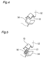
- the lock member 12 is cut and bent upward at two diametrically opposing positions of the inner periphery thereof to form substantially rectangular engaging portions 13 (first engaging portions), each of which is open at the inner periphery and at one circumferential end thereof.
- the cap member 7, which is secured to the piston rod 3, is cut and bent downward at two diametrically opposing positions thereof closer to the inner periphery thereof that face the engaging portions 13 of the lock member 12 to form substantially rectangular engaging pieces 14 (second engaging portions) that extend diametrically from the outer periphery of the piston rod 3.
- the cap member 7 has windows 15 (openings) formed as the result of cutting and bending downward the engaging pieces 14.
- the windows 15 have the same configuration as that of the engaging pieces 14.
- the engaging pieces 14 are engaged with the respective lower sides of the engaging portions 13 of the lock member 12 through the openings of the engaging portions 13 by rotating the cap member 7 in a state where the piston rod 3 has been contracted substantially to its minimum length position.
- the engaging portions 13 engage with the respective upper sides of the engaging pieces 14 (i.e. the respective sides thereof closer to the distal end of the piston rod 3).
- the piston rod 3 can be locked in its minimum length position.
- the cap member 7 is secured to the piston rod 3 by welding and hence rotate together with the piston rod 3 (i.e. the piston).
- the cap member 7, however, may be fitted rotatably relative to the piston rod 3.
- the sliding movement of the piston caused by the extension and contraction of the piston rod 3 induces a flow of hydraulic fluid in the hydraulic fluid passages in the cylinder part 2.
- the flow of hydraulic fluid is controlled by the damping force generating mechanism comprising orifices and disk valves to generate a damping force.
- the damping force generating mechanism comprising orifices and disk valves to generate a damping force.
- a volumetric change in the cylinder 2A due to the entry and withdrawal of the piston rod 3 is compensated for by the compression and expansion of the gas in the reservoir 6 or the gas chamber.
- the piston rod 3 is constantly subjected to a force in the direction of extension by the pressure of gas in the reservoir 4 or the gas chamber.
- the piston rod 3 is contracted to near its minimum length position against the pressure of gas in the reservoir 4 or the gas chamber.
- the cap member 7 is rotated to engage the engaging pieces 14 of the cap member 7, which is secured to the piston rod 3, with the engaging portions 13 of the lock member 12, which is secured to the cylinder part 2.
- the piston rod 3 can be locked in its minimum length position.
- the engaging portions 13 and the engaging pieces 14 are formed by cutting and bending the disk-shaped lock member 12 and cap member 7, respectively, the axial length thereof can be made sufficiently small. Therefore, the engaging portions 13 and the engaging pieces 14 exert substantially no influence on the stroke of the piston rod 3.
- each engaging piece 14 has a plurality of tooth grooves 16 formed on an engaging surface thereof.
- Each engaging portion 13 has projections 17 projecting to face the tooth grooves 16. Meshing between the tooth grooves 16 and the projections 17 can firmly maintain the engaged condition of the engaging portions 13 and the engaging pieces 14. With this structure, it is possible to prevent the piston rod 3 from being accidentally unlocked. To unlock the piston rod 3, it is pressed in the direction of contraction to cancel the meshing between the tooth grooves 16 and the projections 17. Thus, the engaging portions 13 and the engaging pieces 14 can be disengaged from each other.
- each engaging portion 13 at the side thereof closer to the circumferential opening is bent inwardly to project inwardly, thereby forming a retaining projection 18.
- the lock member 12 in this embodiment has a pair of upwardly bent engaging portions 19 (first engaging portions) at two diametrically opposing positions of the inner periphery thereof.
- the respective distal ends of the pair of engaging portions 19 are bent in mutually opposite directions to form hook-shaped (L-shaped) latch portions 20.
- the cap member 7 has a pair of engaging holes 21 (second engaging portions) opened to face the pair of engaging portions 19 of the lock member 12.
- the engaging holes 21 allow the engaging portions 19 to be inserted therethrough.
- the piston rod 3 contracted substantially to its minimum length position the engaging portions 19 are inserted through the engaging holes 21.
- the cap member 7 is rotated to engage the latch portions 20 at the distal ends of the engaging portions 19 with the respective edges of the engaging holes 21.
- the piston rod 3 can be locked in its minimum length position.
- the piston rod 3 To unlock the piston rod 3, it is rotated in the direction opposite to the direction for locking to disengage the latch portions 20 of the engaging portions 19 from the edges of the engaging holes 21. In this way, the piston rod 3 can be unlocked. It should be noted that if the piston rod 3 is rotated while pressing it in the direction of contraction, the latch portions 20 can be smoothly disengaged from the edges of the engaging holes 21.
- the engaging portions 19 engage with the respective edges of the engaging holes 21 at the outer sides thereof (i.e. at the sides thereof closer to the distal end of the piston rod 3), the engaged condition can be visually confirmed easily.
- locking and unlocking of the piston rod 3 can be performed easily and reliably.
- the present invention is applied to a hydraulic shock absorber, it should be noted that the present invention is similarly applicable to other cylinder apparatus such as a hydraulic cylinder, a gas spring, etc. in which a rod extends from a cylinder part.
- the rod can be locked in its minimum length position by a lock mechanism provided on the cylinder part and the cap member, without using either a band or a wire. Further, the locked condition can be visually confirmed easily because the first engaging portions of the lock member of the cylinder part engage with the second engaging portions of the cap member at the respective sides of the second engaging portions closer to the distal end of the rod.
Landscapes
- Engineering & Computer Science (AREA)
- General Engineering & Computer Science (AREA)
- Mechanical Engineering (AREA)
- Fluid-Damping Devices (AREA)
Applications Claiming Priority (1)
| Application Number | Priority Date | Filing Date | Title |
|---|---|---|---|
| JP2007199658A JP4958002B2 (ja) | 2007-07-31 | 2007-07-31 | シリンダ装置 |
Publications (2)
| Publication Number | Publication Date |
|---|---|
| EP2020529A2 true EP2020529A2 (de) | 2009-02-04 |
| EP2020529A3 EP2020529A3 (de) | 2009-10-07 |
Family
ID=39884206
Family Applications (1)
| Application Number | Title | Priority Date | Filing Date |
|---|---|---|---|
| EP08012734A Withdrawn EP2020529A3 (de) | 2007-07-31 | 2008-07-15 | Zylindrischer Apparat mit einer verriegelbaren Kolbenstange |
Country Status (4)
| Country | Link |
|---|---|
| US (1) | US8047341B2 (de) |
| EP (1) | EP2020529A3 (de) |
| JP (1) | JP4958002B2 (de) |
| CN (1) | CN101358628B (de) |
Cited By (1)
| Publication number | Priority date | Publication date | Assignee | Title |
|---|---|---|---|---|
| EP2256364A3 (de) * | 2009-05-27 | 2011-11-02 | AL-KO Kober AG | Zylinderanordnung |
Families Citing this family (3)
| Publication number | Priority date | Publication date | Assignee | Title |
|---|---|---|---|---|
| JP2014213892A (ja) * | 2013-04-25 | 2014-11-17 | 日立オートモティブシステムズ株式会社 | 輸送用保護部材 |
| KR101461892B1 (ko) * | 2013-06-21 | 2014-11-13 | 현대자동차 주식회사 | 자동차의 쇽업소버 하우징 |
| JP6149020B2 (ja) * | 2014-10-14 | 2017-06-14 | Kyb株式会社 | ショックアブソーバ |
Citations (2)
| Publication number | Priority date | Publication date | Assignee | Title |
|---|---|---|---|---|
| JPH02132147A (ja) | 1988-08-04 | 1990-05-21 | Teijin Chem Ltd | ポリカーボネート組成物 |
| JPH02132147U (de) | 1988-12-16 | 1990-11-02 |
Family Cites Families (9)
| Publication number | Priority date | Publication date | Assignee | Title |
|---|---|---|---|---|
| DE2345503C2 (de) * | 1973-09-08 | 1983-04-14 | Stabilus Gmbh, 5400 Koblenz | Ausstellvorrichtung für schwenkbare Klappen |
| JPS628412Y2 (de) * | 1981-06-03 | 1987-02-27 | ||
| JPS5812744A (ja) * | 1981-07-17 | 1983-01-24 | Hitachi Ltd | 強化反応射出成形構造体及びその成形法 |
| DE3128698C2 (de) | 1981-07-21 | 1984-01-19 | Heraeus Quarzschmelze Gmbh, 6450 Hanau | Quarzglashüllrohr |
| JPS5820740U (ja) * | 1981-08-01 | 1983-02-08 | 厚木自動車部品株式会社 | ガス封入緩衝器の短縮構造 |
| JP4013952B2 (ja) | 2002-06-19 | 2007-11-28 | サンケン電気株式会社 | Dc−dcコンバータ |
| JP2004124994A (ja) * | 2002-09-30 | 2004-04-22 | Tokico Ltd | シリンダ装置 |
| DE102005015564A1 (de) * | 2005-04-05 | 2006-10-12 | Stabilus Gmbh | Kolben-Zylinderaggregat |
| JP4564905B2 (ja) * | 2005-08-30 | 2010-10-20 | カヤバ工業株式会社 | ステーダンパ |
-
2007
- 2007-07-31 JP JP2007199658A patent/JP4958002B2/ja active Active
-
2008
- 2008-07-15 EP EP08012734A patent/EP2020529A3/de not_active Withdrawn
- 2008-07-22 US US12/219,425 patent/US8047341B2/en not_active Expired - Fee Related
- 2008-07-31 CN CN2008101448842A patent/CN101358628B/zh not_active Expired - Fee Related
Patent Citations (2)
| Publication number | Priority date | Publication date | Assignee | Title |
|---|---|---|---|---|
| JPH02132147A (ja) | 1988-08-04 | 1990-05-21 | Teijin Chem Ltd | ポリカーボネート組成物 |
| JPH02132147U (de) | 1988-12-16 | 1990-11-02 |
Cited By (1)
| Publication number | Priority date | Publication date | Assignee | Title |
|---|---|---|---|---|
| EP2256364A3 (de) * | 2009-05-27 | 2011-11-02 | AL-KO Kober AG | Zylinderanordnung |
Also Published As
| Publication number | Publication date |
|---|---|
| JP2009036265A (ja) | 2009-02-19 |
| JP4958002B2 (ja) | 2012-06-20 |
| CN101358628B (zh) | 2012-06-20 |
| CN101358628A (zh) | 2009-02-04 |
| US20090032345A1 (en) | 2009-02-05 |
| EP2020529A3 (de) | 2009-10-07 |
| US8047341B2 (en) | 2011-11-01 |
Similar Documents
| Publication | Publication Date | Title |
|---|---|---|
| US8047341B2 (en) | Cylinder apparatus | |
| EP2732998A1 (de) | Schwingungsverhinderungsvorrichtung für ein kraftfahrzeug- öffnungs- und schliesselement sowie stopfenvorrichtung für das kraftfahrzeug-öffnungs- und schliesselement | |
| US20110089706A1 (en) | Absorber element for a motor vehicle lock | |
| EP2122193B1 (de) | Stossdämpferschmutzabweiser | |
| US5275386A (en) | Positioning device | |
| DE102007005690B4 (de) | Verschlusspaket für einen Schwingungsdämpfer und Schwingungsdämpfer mit einem solchen Verschlusspaket | |
| DE102012206458B3 (de) | Kolben-Zylinderaggregat | |
| KR102471852B1 (ko) | 실린더 장치 | |
| CN101793274A (zh) | 缸体装置的制造方法 | |
| CN107076244A (zh) | 缓冲器 | |
| US6263779B1 (en) | Snap ring closure system | |
| US8356386B2 (en) | Door closer | |
| EP3196503A1 (de) | Stossdämpfer | |
| CN102562912B (zh) | 缸体装置 | |
| US11585401B2 (en) | Annular sealing unit for guiding a mono-tube shock absorber | |
| EP2071218B1 (de) | Stossdämpfer mit Rückschlagventil | |
| CN111247353B (zh) | 缓冲器 | |
| US20160010715A1 (en) | Shock absorber | |
| EP4224034A1 (de) | Hydraulischer endanschlag für einzelrohrdämpfer | |
| US20230250858A1 (en) | Hydraulic rebound stop for monotube damper | |
| JP2009036265A5 (de) | ||
| CN110650855A (zh) | 封闭装置及其用途、封锁流体通道的方法和空气弹簧系统 | |
| JP2004124994A (ja) | シリンダ装置 | |
| CN109307035B (zh) | 缓冲器和罩部件 | |
| JPH1122772A (ja) | ガススプリング |
Legal Events
| Date | Code | Title | Description |
|---|---|---|---|
| PUAI | Public reference made under article 153(3) epc to a published international application that has entered the european phase |
Free format text: ORIGINAL CODE: 0009012 |
|
| AK | Designated contracting states |
Kind code of ref document: A2 Designated state(s): AT BE BG CH CY CZ DE DK EE ES FI FR GB GR HR HU IE IS IT LI LT LU LV MC MT NL NO PL PT RO SE SI SK TR |
|
| AX | Request for extension of the european patent |
Extension state: AL BA MK RS |
|
| PUAL | Search report despatched |
Free format text: ORIGINAL CODE: 0009013 |
|
| AK | Designated contracting states |
Kind code of ref document: A3 Designated state(s): AT BE BG CH CY CZ DE DK EE ES FI FR GB GR HR HU IE IS IT LI LT LU LV MC MT NL NO PL PT RO SE SI SK TR |
|
| AX | Request for extension of the european patent |
Extension state: AL BA MK RS |
|
| 17P | Request for examination filed |
Effective date: 20100323 |
|
| 17Q | First examination report despatched |
Effective date: 20100430 |
|
| AKX | Designation fees paid |
Designated state(s): DE |
|
| STAA | Information on the status of an ep patent application or granted ep patent |
Free format text: STATUS: THE APPLICATION IS DEEMED TO BE WITHDRAWN |
|
| 18D | Application deemed to be withdrawn |
Effective date: 20120731 |