EP2020537A2 - Unité de changement pour une boîte de vitesse électronique - Google Patents
Unité de changement pour une boîte de vitesse électronique Download PDFInfo
- Publication number
- EP2020537A2 EP2020537A2 EP08012562A EP08012562A EP2020537A2 EP 2020537 A2 EP2020537 A2 EP 2020537A2 EP 08012562 A EP08012562 A EP 08012562A EP 08012562 A EP08012562 A EP 08012562A EP 2020537 A2 EP2020537 A2 EP 2020537A2
- Authority
- EP
- European Patent Office
- Prior art keywords
- selector lever
- switching unit
- unit according
- positions
- selector
- Prior art date
- Legal status (The legal status is an assumption and is not a legal conclusion. Google has not performed a legal analysis and makes no representation as to the accuracy of the status listed.)
- Withdrawn
Links
Images
Classifications
-
- F—MECHANICAL ENGINEERING; LIGHTING; HEATING; WEAPONS; BLASTING
- F16—ENGINEERING ELEMENTS AND UNITS; GENERAL MEASURES FOR PRODUCING AND MAINTAINING EFFECTIVE FUNCTIONING OF MACHINES OR INSTALLATIONS; THERMAL INSULATION IN GENERAL
- F16H—GEARING
- F16H59/00—Control inputs to control units of change-speed- or reversing-gearings for conveying rotary motion
- F16H59/02—Selector apparatus
- F16H59/0204—Selector apparatus for automatic transmissions with means for range selection and manual shifting, e.g. range selector with tiptronic
-
- F—MECHANICAL ENGINEERING; LIGHTING; HEATING; WEAPONS; BLASTING
- F16—ENGINEERING ELEMENTS AND UNITS; GENERAL MEASURES FOR PRODUCING AND MAINTAINING EFFECTIVE FUNCTIONING OF MACHINES OR INSTALLATIONS; THERMAL INSULATION IN GENERAL
- F16H—GEARING
- F16H59/00—Control inputs to control units of change-speed- or reversing-gearings for conveying rotary motion
- F16H59/02—Selector apparatus
- F16H59/08—Range selector apparatus
- F16H59/10—Range selector apparatus comprising levers
-
- F—MECHANICAL ENGINEERING; LIGHTING; HEATING; WEAPONS; BLASTING
- F16—ENGINEERING ELEMENTS AND UNITS; GENERAL MEASURES FOR PRODUCING AND MAINTAINING EFFECTIVE FUNCTIONING OF MACHINES OR INSTALLATIONS; THERMAL INSULATION IN GENERAL
- F16H—GEARING
- F16H61/00—Control functions within control units of change-speed- or reversing-gearings for conveying rotary motion ; Control of exclusively fluid gearing, friction gearing, gearings with endless flexible members or other particular types of gearing
- F16H61/24—Providing feel, e.g. to enable selection
-
- F—MECHANICAL ENGINEERING; LIGHTING; HEATING; WEAPONS; BLASTING
- F16—ENGINEERING ELEMENTS AND UNITS; GENERAL MEASURES FOR PRODUCING AND MAINTAINING EFFECTIVE FUNCTIONING OF MACHINES OR INSTALLATIONS; THERMAL INSULATION IN GENERAL
- F16H—GEARING
- F16H59/00—Control inputs to control units of change-speed- or reversing-gearings for conveying rotary motion
- F16H59/02—Selector apparatus
- F16H2059/0221—Selector apparatus for selecting modes, e.g. sport, normal, economy
-
- F—MECHANICAL ENGINEERING; LIGHTING; HEATING; WEAPONS; BLASTING
- F16—ENGINEERING ELEMENTS AND UNITS; GENERAL MEASURES FOR PRODUCING AND MAINTAINING EFFECTIVE FUNCTIONING OF MACHINES OR INSTALLATIONS; THERMAL INSULATION IN GENERAL
- F16H—GEARING
- F16H59/00—Control inputs to control units of change-speed- or reversing-gearings for conveying rotary motion
- F16H59/02—Selector apparatus
- F16H2059/0239—Up- and down-shift or range or mode selection by repeated movement
-
- F—MECHANICAL ENGINEERING; LIGHTING; HEATING; WEAPONS; BLASTING
- F16—ENGINEERING ELEMENTS AND UNITS; GENERAL MEASURES FOR PRODUCING AND MAINTAINING EFFECTIVE FUNCTIONING OF MACHINES OR INSTALLATIONS; THERMAL INSULATION IN GENERAL
- F16H—GEARING
- F16H59/00—Control inputs to control units of change-speed- or reversing-gearings for conveying rotary motion
- F16H59/02—Selector apparatus
- F16H2059/0252—Selector apparatus with means for initiating skip or double gear shifts, e.g. by moving selection lever beyond a threshold
-
- F—MECHANICAL ENGINEERING; LIGHTING; HEATING; WEAPONS; BLASTING
- F16—ENGINEERING ELEMENTS AND UNITS; GENERAL MEASURES FOR PRODUCING AND MAINTAINING EFFECTIVE FUNCTIONING OF MACHINES OR INSTALLATIONS; THERMAL INSULATION IN GENERAL
- F16H—GEARING
- F16H59/00—Control inputs to control units of change-speed- or reversing-gearings for conveying rotary motion
- F16H59/02—Selector apparatus
- F16H2059/0295—Selector apparatus with mechanisms to return lever to neutral or datum position, e.g. by return springs
-
- F—MECHANICAL ENGINEERING; LIGHTING; HEATING; WEAPONS; BLASTING
- F16—ENGINEERING ELEMENTS AND UNITS; GENERAL MEASURES FOR PRODUCING AND MAINTAINING EFFECTIVE FUNCTIONING OF MACHINES OR INSTALLATIONS; THERMAL INSULATION IN GENERAL
- F16H—GEARING
- F16H61/00—Control functions within control units of change-speed- or reversing-gearings for conveying rotary motion ; Control of exclusively fluid gearing, friction gearing, gearings with endless flexible members or other particular types of gearing
- F16H61/24—Providing feel, e.g. to enable selection
- F16H2061/247—Detents for range selectors
-
- F—MECHANICAL ENGINEERING; LIGHTING; HEATING; WEAPONS; BLASTING
- F16—ENGINEERING ELEMENTS AND UNITS; GENERAL MEASURES FOR PRODUCING AND MAINTAINING EFFECTIVE FUNCTIONING OF MACHINES OR INSTALLATIONS; THERMAL INSULATION IN GENERAL
- F16H—GEARING
- F16H63/00—Control outputs from the control unit to change-speed- or reversing-gearings for conveying rotary motion or to other devices than the final output mechanism
- F16H63/40—Control outputs from the control unit to change-speed- or reversing-gearings for conveying rotary motion or to other devices than the final output mechanism comprising signals other than signals for actuating the final output mechanisms
- F16H63/42—Ratio indicator devices
- F16H2063/423—Range indicators for automatic transmissions, e.g. showing selected range or mode
Definitions
- the invention relates to a switching unit for an electronically shifted transmission, comprising a selector lever, which is movable for selecting different gear stages to be inserted in the transmission side in different selection positions.
- the invention is therefore based on the problem to provide a switching unit, which allows the possibility of easy insertion of the P-speed and easy for the driver to use.
- a switching unit of the type mentioned that at least four different speed levels can be selected via the selector lever, wherein the selector lever is movable out of a stable basic position in two opposite directions along which at least three not latched, Selector positions defined by a pressure point are realized, from which the selector lever can be automatically reset to the basic position.
- a total of at least seven separate positions are realized, which make it possible to select the four speed levels PRND can.
- the selector lever itself when not actively moved by the driver, is always in a home position, in which it is automatically returned when moved out of it in one of the selector positions that follow it in that direction.
- the selector positions are assigned to variable speed steps as a function of the variable speed level assigned to the basic position. D.
- the switching unit according to the invention offers a number of advantages.
- the P-drive stage can be integrated into the shift pattern, specifically in the PRND sequence known per se.
- the driver the circuit diagram known to him for a long time even with electronically connected transmissions or electronic switching units.
- the monostable design in which therefore the selector lever is always in the basic position, has no "pointing effect", in contrast to known latched selector levers, which thus remain in the respective selection position.
- the selector lever or the basic position is when restarting automatically assigned the P-speed, starting from which then the selector lever can be moved in accordance with the predetermined shift pattern for selecting a different speed level. Even with a system failure, the selector lever is always in the same basic position, the driver can be warned by a display or other display.
- the selector lever can be moved against a mechanical return element in the respective direction.
- the mechanical restoring element is preferably a spring, which is tensioned accordingly when moving from the basic position into the first, second or third selection position. It is also conceivable to integrate the mechanical return element quasi in the selector lever, via a mechanical guide of the lever on a backdrop mitels a spring-loaded roller, which runs sprung on the backdrop. The scenery and the spring are designed in such a way that the spring, which loads the roller, can always bring the lever to its original position under the return of the roller on the gate.
- the selector lever can also be reset via an electrical or electro-mechanical or hydraulic or pneumatic return means.
- an electromagnet which is driven by moving the selector lever in a specific selection position and detecting the same via a suitable sensor to retract the selector lever back to the basic position.
- hydraulic or pneumatic return means for example in the form of suitable actuating cylinder, are conceivable.
- the individual pressure points themselves which are realized over the entire movement length, are expediently realized via a mechanical guidance of the selector lever, in particular a slotted guide, on or in which the selector lever slides.
- a guide has, for example, a corrugated guide profile on which the lower end of the pivotable selector lever runs, for example via a spring-loaded roller.
- Each selection position can be realized, for example, via a trough into which the guide roller enters, which can be felt haptically. To move out of the sink must be worked against the rising profile again, which is also tactile.
- the automatic return of the lever can also be done as described on the lever side integrated spring-loaded roller itself, in which case the backdrop has no sinks.
- the switching unit is expediently assigned a switching means via which the functionality of the switching unit can be reversibly switched to a manual tap-change of individual gears.
- the driver can therefore by operating a switching means, such as a button on the steering wheel, change the functionality of the switching unit from the conventional functionality, in the context of which the known driving levels PRND are selectable, to a manual tap-change, in the context of which the selector lever starting from Move up or down in the home position by moving forward to the next pressure point or in the opposite direction until the next pressure point.
- a switching means such as a button on the steering wheel
- the gear can be up or downshifted. That is, when the selector lever is pulled back by the driver in the first pressure point, is shifted down by a first gear, the selector lever is pulled further into the second pressure point, a second gear is downshifted.
- the third pressure point following in the respective direction is used as the third switching point. This allows a much faster switching in the context of the jog dial than conventional, where the selector lever for shifting each a gear from the basic position to the switching position must be moved and released again, for switching another gear, this process is carried out again.
- the driver pulls the selector lever only two or three pressure points, the transmission follows immediately.
- the switching unit according to the invention also from a first shift gate, along which the selector lever is movable to switch the speed levels, branch off a second shift gate, in which the Selector lever for a manual tap-shift individual gears is movable. So if you want to switch to jogging, so the driver has to move the selector lever again starting from the basic position, for example, a short distance to the right in the second shift gate, where then the jogging is given.
- the selector lever starting from a basic position in this second shift gate is movable in two opposite directions, along which at least two non-latched, selected via a pressure point selection positions are realized from which the selector lever automatically reset to the basic position wherein, starting from the home position when moving in at least two consecutive pressure points in one direction upon reaching each pressure point, a gear is up or downshiftable.
- a separate second jogging Kunststoffgasse can be achieved by realizing two or more pressure point a much faster switching, because the selector lever, for example, to downshift two gears only once to pull in the two successive pressure points.
- the selector lever in the basic position in which it is always located as described, the P-speed assigned, for example, at a restart of the car the following driving steps R, N and D can only by moving in one direction, namely by moving to the rear pulling the selector lever can be selected, as a result of the realization of the rigid circuit diagram PRND.
- the selector lever movement can basically be mechanically blocked from the basic position or from or to any desired selection position. D. h., About this blocking possibility, the selector lever can be moved in any direction only as far as the next respective pressure point or the next following dialing position is assigned a selectable gear at all.
- All other selector lever positions are mechanically locked, including, for example, a mechanical or electromechanical locking element is provided, for.
- a mechanical or electromechanical locking element is provided, for.
- an electromagnet which provides a pawl or the like, which engages in a corresponding guide or locking gate, the corresponding locking receptacles for the pawl, and prevents a corresponding movement of the selector lever.
- the selector lever is always movable in principle, that is also in a selectable position can be brought, which is associated with no gear, but in this case then inevitably no speed control circuit.
- the driver has not switched over to the optional manual tipping circuit to which all three pressure points or selection positions are permissible. If, for example, only two pressure points or selection positions are assigned in each direction, then the respective third position can also be mechanically locked, for example, or no switching takes place in this despite selector lever movement.
- a display means is expediently provided on the switching unit, optionally an external indicating means may also be provided here.
- the basic driving sequence PRND can be specified, for example, as a permanently installed representation on the switching unit for the basic orientation of the driver, so that he knows in which direction he has to move the lever starting from the basic position driving position shown.
- the display means may also have a plurality of display positions corresponding to the number and preferably the position at basic and selection positions for the engaged and the selectable driving steps. In this embodiment of the invention, therefore, a maximum of seven display positions are given, on which the driving steps that can be selected there in each case can be displayed. Depending on which gear position is assigned to the basic position, ultimately the display changes constantly, but there are a maximum of four displays that just indicate the ever selectable driving levels P-R-N-D. Display positions that are assigned to dialing items without the ability to select a speed level or that have the blocked dialing positions assigned are not in operation.
- either a separate switching element can be provided for this purpose, which can be activated, for example, only if the previously selected gear is the D-speed, so therefore the selector lever basic position is assigned. It would also be conceivable, however, for the selector lever, starting from the basic position, to be able to be moved into a further selector position which branches off to the left, for example, but in which case it is then optionally locked. This branch is, if a manual jogging circuit is provided with a separate second shift gate, opposite to the direction of movement in the second shift gate.
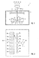
- Fig. 1 shows a switching unit 1 according to the invention, comprising a selector lever 2 which is pivotable about a pivot axis 3. It is associated with a mechanical guide 5 in the form of a slotted guide in a housing 4 of the switching unit 1, along which it runs over a loaded via a spring 6 running element 7.
- the guide 5 has seven recesses 9, each of which produces pressure points 8.
- the selector lever 2 itself is against a return element 10, here formed by way of example two springs 11, starting from the in Fig. 1 shown basic position, in which he is in the middle of the seven excellent selection positions, movable.
- This middle selection position defined via the middle pressure point 8 represents the basic position in which the selector lever 2 is automatically brought over the return element 10 when it is relieved. This position is thus stable, while all other selection positions, defined via the respective pressure point 8, are unstable, the selector lever 2 in this therefore not locked.
- Fig. 2 shows a plan view of the switching unit 1 from Fig. 1 , but here for the sake of clarity, the selector lever 2 itself is not shown, however the switching or movement scheme. Shown are the one hand, the basic position 12, defined by the middle pressure point 8 and the central recess 9 on the guide 5, and the individual selection positions 13a - 13f, of which three in the one and three in the other direction of movement, starting from the Basic position 12, are selectable. Furthermore, a second shift gate 15 is set parallel to this shift gate 14, in which the selector lever 2 can be transferred. There, a manual tipping circuit is possible, ie, the driver can hereby up or down gears by tapping forward or backward gears. In this second shift gate 15, the selector lever 2 rests, ie, it is not automatically returned to the first shift gate 14, in which the drive stages PRND can be selected. This must be done by the driver.
- a display device 16 which in the example shown has seven display positions 17a-17f, of which one of the basic position 12 or each dial position 13a-13f is assigned.
- the selector lever 2 is in the basic position 12. This can be assigned to any of the four speed steps P-R-N-D, depending on which was previously set either automatically on the transmission side or selected by the driver.
- the respective currently assigned to the basic position 12 gear is displayed on the associated display position 17, which is intuitively positioned directly next to it.
- the other selectable speed steps are represented according to the fixed shift pattern P-R-N-D by means of the display positions 17a-17f associated with the adjacent dial positions 13a-13f.
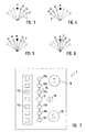
- the driver thus recognizes immediately up to which dialing position 13d, 13e, 13f he has to move the selector lever to engage the desired gear. It is assumed that the driver wants to engage the D-speed. He therefore pulls the selector lever 2 via the selection positions 13d and 13e associated pressure points 8 to the pressure point 8, which defines the selection position 13f.
- the displayed D-symbol in the display position 17f for example, lights a little brighter to signal that actually this gear is selected.
- the sensor system detects the selection of the D gear position, at the same time the selector lever 2 is returned to the basic position 12 via the return element 10. In the display position 17 then lights when the D-speed was engaged, the D-symbol.
- the result of the D-speed step selection according to Fig. 3 is in Fig. 4 shown.
- the selector lever is forced to move into one of the selector positions 13a-13c.
- the dialing position 13a would be the N-speed step
- the dialing position 13b the R-speed step
- the dialing position 13c the P-speed step.
- an "N” symbol would be displayed, in the display position 17b an "R” symbol and in the display position 17b a "P” symbol to assist the driver give.
- the dial positions 13d-13f would again be disabled in this case because they have no selectable speed levels assigned to them.
- Fig. 5 shows another dialing scheme.
- the selector lever 2 in the basic position 12, the N-speed assigned. If the driver now wants to engage the D drive position, then the selector lever would have to follow the rigid pattern PRND to move downwards into the selection position 13d; in the display position 17d, the "D" symbol would be displayed. To select the R-drive level, the selector lever would have to be moved to the selection position 13a to select the P-drive level to the selection position 13b. Corresponding "R" and "P” symbols would be shown in the associated display positions 17a, 17b.
- the circuit diagram is composed when the basic position 12, the R-speed is assigned.
- the selector lever would have to be moved to the selection position 13a, to select the N and D-speed step in the selection positions 13d or 13e.
- Corresponding "P", "R”, “N” and “D” symbols would be shown in the corresponding display positions 17a, 17d and 17e.
- Fig. 7 shows a further embodiment of a switching unit 1 according to the invention, the functionality of the choice of the driving levels PRND of the switching unit 1 from the Fig. 1 - 6 equivalent.
- a switching means 18 is provided in the form of a button, which is marked with a +/- symbol. If this switching means 18 is actuated, the functionality of the switching unit 1 is changed over from a drive level functionality to a jogging functionality, which, however, is still implemented in the shift gate 14.
- the selector lever is always in the home position 12.
- At least the selector positions 13a and 13d are provided with switching functions via which the respectively engaged gear can be manually shifted up or down. This is shown to the driver by the "+" symbol in the display position 17a and the "-" symbol in the display position 17d, ie, it recognizes in which direction he must move the selector lever 2 to upshift a gear ( +) or to downshift a gear (-).
- a first gear is downshifted, pulled further to the select position 13e, downshifted by a second gear and, if provided or permitted by the transmission, upon movement into the gearbox Select position 13f is downshifted by a third gear. That is, in a single movement, it is possible to downshift by several gears without the driver having to set down for this, as in the manual shift in accordance with Fig. 2 the case would be. If the driver leaves the selector lever after reaching positions 13e or 13f, for example, he returns to the basic position 12. If the driver now wants to shift up again, the selector lever 2 would have to be moved in the opposite direction to one of the positions 13a, 13b or 13c, it also being possible to increase one, two or three speeds in one movement movement.
- a further shift gate 19 which serves to select a sports driving gear S, is shown by dashed lines.
- the selector lever can, for example, only when the basic position is assigned to the gear D, are placed to the right in this shift gate 19, where he rests. It is then inserted the S-drive.
- a switching element 20 which is likewise shown only by dashed lines. If this switching element 20, which is activated, for example, only when the basic position 12 is assigned to the driving position D, pressed, the S-speed is automatically engaged.
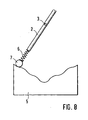
- Fig. 8 shows a further embodiment of a slotted guide 5, in conjunction with the lever side arranged spring 6 and the running element 7, preferably a roller, an automatic mechanical lever return allows.
- the top of the guide 5 is profiled wavy, but points, unlike in Fig. 1 , no excellent sinks.
- the spring 6 can because of their restoring force return the lever from each selection position back to the normal position, however, a sufficient feel on the wavy surface structure is guaranteed.
Landscapes
- Engineering & Computer Science (AREA)
- General Engineering & Computer Science (AREA)
- Mechanical Engineering (AREA)
- Arrangement Or Mounting Of Control Devices For Change-Speed Gearing (AREA)
- Control Of Transmission Device (AREA)
- Gear-Shifting Mechanisms (AREA)
Applications Claiming Priority (1)
| Application Number | Priority Date | Filing Date | Title |
|---|---|---|---|
| DE200710036086 DE102007036086A1 (de) | 2007-08-01 | 2007-08-01 | Schalteinheit für ein elektronisch geschaltetes Getriebe |
Publications (2)
| Publication Number | Publication Date |
|---|---|
| EP2020537A2 true EP2020537A2 (fr) | 2009-02-04 |
| EP2020537A3 EP2020537A3 (fr) | 2010-08-11 |
Family
ID=39884616
Family Applications (1)
| Application Number | Title | Priority Date | Filing Date |
|---|---|---|---|
| EP08012562A Withdrawn EP2020537A3 (fr) | 2007-08-01 | 2008-07-11 | Unité de changement pour une boîte de vitesse électronique |
Country Status (2)
| Country | Link |
|---|---|
| EP (1) | EP2020537A3 (fr) |
| DE (1) | DE102007036086A1 (fr) |
Cited By (5)
| Publication number | Priority date | Publication date | Assignee | Title |
|---|---|---|---|---|
| EP2676051A2 (fr) * | 2011-02-18 | 2013-12-25 | Bayerische Motoren Werke Aktiengesellschaft | Véhicule comportant une boîte de vitesses et un dispositif de sélection à actionnement manuel |
| CN110630738A (zh) * | 2018-06-21 | 2019-12-31 | 广州汽车集团股份有限公司 | 一种自复位式电子换挡器 |
| CN111902659A (zh) * | 2018-06-18 | 2020-11-06 | 宝马股份公司 | 用于机动车变速器的选择装置、机动车以及用于运行这种选择装置的方法 |
| CN112984105A (zh) * | 2019-12-16 | 2021-06-18 | 采埃孚股份公司 | 用于设定或选择车辆行驶状态和/或行驶模式的换挡设备 |
| CN115076355A (zh) * | 2022-08-24 | 2022-09-20 | 杭州银轩机械有限公司 | 一种挡位控制装置 |
Families Citing this family (7)
| Publication number | Priority date | Publication date | Assignee | Title |
|---|---|---|---|---|
| DE102007047120B4 (de) * | 2007-10-02 | 2013-01-10 | Audi Ag | Schalteinheit für ein insbesondere elektronisch geschaltetes Getriebe eines Kraftfahrzeugs |
| DE102011004389A1 (de) | 2011-02-18 | 2012-08-23 | Bayerische Motoren Werke Aktiengesellschaft | Fahrzeug mit einer Wähleinrichtung zum Anwählen verschiedener Zustände eines Getriebes |
| DE102011018875A1 (de) * | 2011-04-28 | 2012-10-31 | Audi Ag | Bedieneinrichtung zur Steuerung des Betriebs eines einen Elektromotor umfassenden Kraftfahrzeugs und Kraftfahrzeug |
| DE102011087330A1 (de) * | 2011-11-29 | 2013-05-29 | Bayerische Motoren Werke Aktiengesellschaft | Betätigungsvorrichtung für ein Getriebe eines Kraftfahrzeugs |
| CN102705503B (zh) * | 2012-06-19 | 2014-12-24 | 奇瑞汽车股份有限公司 | 换档变速装置及汽车 |
| DE102015120300B4 (de) * | 2015-11-24 | 2020-09-24 | Dr. Ing. H.C. F. Porsche Aktiengesellschaft | Schalteinrichtung |
| CN109424740A (zh) * | 2017-08-29 | 2019-03-05 | 东风(十堰)车身部件有限责任公司 | 一种选换挡操纵器 |
Family Cites Families (12)
| Publication number | Priority date | Publication date | Assignee | Title |
|---|---|---|---|---|
| DE19849076A1 (de) * | 1998-10-24 | 2000-04-27 | Bayerische Motoren Werke Ag | Wähleinrichtung für ein automatisch geschaltetes Getriebe eines Kraftfahrzeugs |
| DE19916924A1 (de) * | 1999-04-14 | 2000-10-19 | Bayerische Motoren Werke Ag | Kraftfahrzeug mit einer Wähleinrichtung |
| US6564661B2 (en) * | 2001-02-01 | 2003-05-20 | Grand Haven Stamped Products, Division Of Jsj Corporation | Storable shifter with electronic gear shift reset |
| DE10112698B4 (de) * | 2001-03-16 | 2010-02-25 | Daimler Ag | Schaltvorrichtung für ein Kraftfahrzeuggetriebe |
| DE10206985B4 (de) * | 2002-02-20 | 2012-07-26 | Bayerische Motoren Werke Aktiengesellschaft | Getriebeschalteinrichtung |
| DE10218233A1 (de) * | 2002-04-24 | 2003-11-06 | Opel Adam Ag | Betriebsart-Steuergerät für ein Automatikgetriebe |
| DE202004004151U1 (de) * | 2004-03-17 | 2004-06-03 | Zf Friedrichshafen Ag | Schaltvorrichtung für automatisierte oder automatische Getriebe |
| DE102004060232A1 (de) * | 2004-12-15 | 2006-06-29 | Leopold Kostal Gmbh & Co. Kg | Elektrische Schalteinrichtung für ein automatisiertes Getriebe |
| DE202004019677U1 (de) * | 2004-12-21 | 2005-03-03 | Daimlerchrysler Ag | Betätigungseinrichtung für ein Automatikgetriebe eines Kraftfahrzeugs |
| DE102005020721A1 (de) * | 2005-05-04 | 2006-11-09 | Dr.Ing.H.C. F. Porsche Ag | Schaltvorrichtung für ein automatisiertes oder automatisches Getriebe |
| DE102005043288A1 (de) * | 2005-09-09 | 2007-03-15 | Leopold Kostal Gmbh & Co. Kg | Elektrische Schalteinrichtung für ein Kraftfahrzeug |
| DE102005062296B3 (de) * | 2005-12-24 | 2007-08-09 | Dr.Ing.H.C. F. Porsche Ag | Getriebeschaltvorrichtung |
-
2007
- 2007-08-01 DE DE200710036086 patent/DE102007036086A1/de not_active Withdrawn
-
2008
- 2008-07-11 EP EP08012562A patent/EP2020537A3/fr not_active Withdrawn
Cited By (6)
| Publication number | Priority date | Publication date | Assignee | Title |
|---|---|---|---|---|
| EP2676051A2 (fr) * | 2011-02-18 | 2013-12-25 | Bayerische Motoren Werke Aktiengesellschaft | Véhicule comportant une boîte de vitesses et un dispositif de sélection à actionnement manuel |
| CN111902659A (zh) * | 2018-06-18 | 2020-11-06 | 宝马股份公司 | 用于机动车变速器的选择装置、机动车以及用于运行这种选择装置的方法 |
| CN110630738A (zh) * | 2018-06-21 | 2019-12-31 | 广州汽车集团股份有限公司 | 一种自复位式电子换挡器 |
| CN112984105A (zh) * | 2019-12-16 | 2021-06-18 | 采埃孚股份公司 | 用于设定或选择车辆行驶状态和/或行驶模式的换挡设备 |
| CN115076355A (zh) * | 2022-08-24 | 2022-09-20 | 杭州银轩机械有限公司 | 一种挡位控制装置 |
| CN115076355B (zh) * | 2022-08-24 | 2022-11-18 | 杭州银轩机械有限公司 | 一种挡位控制装置 |
Also Published As
| Publication number | Publication date |
|---|---|
| EP2020537A3 (fr) | 2010-08-11 |
| DE102007036086A1 (de) | 2009-02-05 |
Similar Documents
| Publication | Publication Date | Title |
|---|---|---|
| EP2020537A2 (fr) | Unité de changement pour une boîte de vitesse électronique | |
| EP1338831B1 (fr) | Dispositif de changement de vitesse pour transmission | |
| DE102009039113B4 (de) | Schalteinheit für ein insbesondere elektronisch geschaltetes Getriebe eines Kraftfahrzeugs | |
| DE102007010052B4 (de) | Steuer-/Regelvorrichtung für ein Automatikgetriebe | |
| DE102005041569A1 (de) | Gangschaltungsvorrichtung und Verfahren zum Steuern derselben | |
| DE102018204870A1 (de) | Getriebevorrichtung und Getriebesystem | |
| DE112011100277T5 (de) | Schaltvorrichtung | |
| EP2220402A2 (fr) | Dispositif d'actionnement à arbre à coulisse | |
| WO2008074375A1 (fr) | Elément de commande de commutation pour une boîte de vitesses d'un véhicule automobile avec commutation à commande électronique | |
| DE102007047120B4 (de) | Schalteinheit für ein insbesondere elektronisch geschaltetes Getriebe eines Kraftfahrzeugs | |
| DE19737296C2 (de) | Selbsttätige Schaltvorrichtung eines Gangwechselgetriebes mit einem Handwählorgan | |
| DE102010060577A1 (de) | Einrichtung zum Auswählen von Schaltzuständen bei einem Kraftfahrzeuggetriebe | |
| EP1801463B1 (fr) | Dispositif pour changer la vitesse pour une boîte de vitesses | |
| DE3337930C2 (de) | Wählschalter in einer Schaltsteuerung für Automatgetriebe | |
| EP0770802B1 (fr) | Dispositif de changement de vitesse pour une boíte de vitesses d'un véhicule automobile avec freinage de l'arbre d'entrée pendant la selection de la marche arrière | |
| DE102015120300B4 (de) | Schalteinrichtung | |
| DE102005048875B4 (de) | Schalteinheit für ein elektronisch geschaltetes Getriebe eines Kraftfahrzeugs | |
| DE102004060232A1 (de) | Elektrische Schalteinrichtung für ein automatisiertes Getriebe | |
| DE102006007008B4 (de) | Kraftfahrzeug mit wenigstens einem Fahrerassistenzsystem | |
| DE19849076A1 (de) | Wähleinrichtung für ein automatisch geschaltetes Getriebe eines Kraftfahrzeugs | |
| DE10209840B4 (de) | Automatisiertes Schaltgetriebe mit Bedienungsschnittstelle | |
| DE102006008816B4 (de) | Schalteinrichtung für ein elektronisch geschaltetes Getriebe eines Kraftfahrzeugs | |
| DE10022043B4 (de) | Steuereinrichtung für ein automatisch betätigbares Getriebe eines Kraftfahrzeuges | |
| DE102005025888A1 (de) | Schalteinheit für elektronisch geschaltetes Getriebe in Kraftfahrzeugen | |
| DE10105491A1 (de) | Shift-by-wire Schaltung |
Legal Events
| Date | Code | Title | Description |
|---|---|---|---|
| PUAI | Public reference made under article 153(3) epc to a published international application that has entered the european phase |
Free format text: ORIGINAL CODE: 0009012 |
|
| AK | Designated contracting states |
Kind code of ref document: A2 Designated state(s): AT BE BG CH CY CZ DE DK EE ES FI FR GB GR HR HU IE IS IT LI LT LU LV MC MT NL NO PL PT RO SE SI SK TR |
|
| AX | Request for extension of the european patent |
Extension state: AL BA MK RS |
|
| PUAL | Search report despatched |
Free format text: ORIGINAL CODE: 0009013 |
|
| AK | Designated contracting states |
Kind code of ref document: A3 Designated state(s): AT BE BG CH CY CZ DE DK EE ES FI FR GB GR HR HU IE IS IT LI LT LU LV MC MT NL NO PL PT RO SE SI SK TR |
|
| AX | Request for extension of the european patent |
Extension state: AL BA MK RS |
|
| RIC1 | Information provided on ipc code assigned before grant |
Ipc: F16H 59/10 20060101ALI20100706BHEP Ipc: F16H 61/24 20060101ALI20100706BHEP Ipc: F16H 59/02 20060101AFI20081124BHEP |
|
| STAA | Information on the status of an ep patent application or granted ep patent |
Free format text: STATUS: THE APPLICATION HAS BEEN WITHDRAWN |
|
| 18W | Application withdrawn |
Effective date: 20100929 |