EP2020547A2 - Dispositif de dérivation d'eau - Google Patents
Dispositif de dérivation d'eau Download PDFInfo
- Publication number
- EP2020547A2 EP2020547A2 EP20080157506 EP08157506A EP2020547A2 EP 2020547 A2 EP2020547 A2 EP 2020547A2 EP 20080157506 EP20080157506 EP 20080157506 EP 08157506 A EP08157506 A EP 08157506A EP 2020547 A2 EP2020547 A2 EP 2020547A2
- Authority
- EP
- European Patent Office
- Prior art keywords
- slide way
- way section
- sliding shaft
- stop position
- retaining hook
- Prior art date
- Legal status (The legal status is an assumption and is not a legal conclusion. Google has not performed a legal analysis and makes no representation as to the accuracy of the status listed.)
- Granted
Links
Images


Classifications
-
- F—MECHANICAL ENGINEERING; LIGHTING; HEATING; WEAPONS; BLASTING
- F16—ENGINEERING ELEMENTS AND UNITS; GENERAL MEASURES FOR PRODUCING AND MAINTAINING EFFECTIVE FUNCTIONING OF MACHINES OR INSTALLATIONS; THERMAL INSULATION IN GENERAL
- F16K—VALVES; TAPS; COCKS; ACTUATING-FLOATS; DEVICES FOR VENTING OR AERATING
- F16K11/00—Multiple-way valves, e.g. mixing valves; Pipe fittings incorporating such valves
- F16K11/02—Multiple-way valves, e.g. mixing valves; Pipe fittings incorporating such valves with all movable sealing faces moving as one unit
- F16K11/04—Multiple-way valves, e.g. mixing valves; Pipe fittings incorporating such valves with all movable sealing faces moving as one unit comprising only lift valves
- F16K11/044—Multiple-way valves, e.g. mixing valves; Pipe fittings incorporating such valves with all movable sealing faces moving as one unit comprising only lift valves with movable valve members positioned between valve seats
- F16K11/0445—Bath/shower selectors
-
- E—FIXED CONSTRUCTIONS
- E03—WATER SUPPLY; SEWERAGE
- E03C—DOMESTIC PLUMBING INSTALLATIONS FOR FRESH WATER OR WASTE WATER; SINKS
- E03C1/00—Domestic plumbing installations for fresh water or waste water; Sinks
- E03C1/02—Plumbing installations for fresh water
- E03C1/021—Devices for positioning or connecting of water supply lines
- E03C1/023—Devices for positioning or connecting of water supply lines with flow distribution, e.g. diverters
-
- Y—GENERAL TAGGING OF NEW TECHNOLOGICAL DEVELOPMENTS; GENERAL TAGGING OF CROSS-SECTIONAL TECHNOLOGIES SPANNING OVER SEVERAL SECTIONS OF THE IPC; TECHNICAL SUBJECTS COVERED BY FORMER USPC CROSS-REFERENCE ART COLLECTIONS [XRACs] AND DIGESTS
- Y10—TECHNICAL SUBJECTS COVERED BY FORMER USPC
- Y10T—TECHNICAL SUBJECTS COVERED BY FORMER US CLASSIFICATION
- Y10T137/00—Fluid handling
- Y10T137/8593—Systems
- Y10T137/86493—Multi-way valve unit
- Y10T137/86879—Reciprocating valve unit
-
- Y—GENERAL TAGGING OF NEW TECHNOLOGICAL DEVELOPMENTS; GENERAL TAGGING OF CROSS-SECTIONAL TECHNOLOGIES SPANNING OVER SEVERAL SECTIONS OF THE IPC; TECHNICAL SUBJECTS COVERED BY FORMER USPC CROSS-REFERENCE ART COLLECTIONS [XRACs] AND DIGESTS
- Y10—TECHNICAL SUBJECTS COVERED BY FORMER USPC
- Y10T—TECHNICAL SUBJECTS COVERED BY FORMER US CLASSIFICATION
- Y10T137/00—Fluid handling
- Y10T137/8593—Systems
- Y10T137/877—With flow control means for branched passages
- Y10T137/87708—With common valve operator
- Y10T137/8778—Spring biased
-
- Y—GENERAL TAGGING OF NEW TECHNOLOGICAL DEVELOPMENTS; GENERAL TAGGING OF CROSS-SECTIONAL TECHNOLOGIES SPANNING OVER SEVERAL SECTIONS OF THE IPC; TECHNICAL SUBJECTS COVERED BY FORMER USPC CROSS-REFERENCE ART COLLECTIONS [XRACs] AND DIGESTS
- Y10—TECHNICAL SUBJECTS COVERED BY FORMER USPC
- Y10T—TECHNICAL SUBJECTS COVERED BY FORMER US CLASSIFICATION
- Y10T137/00—Fluid handling
- Y10T137/8593—Systems
- Y10T137/877—With flow control means for branched passages
- Y10T137/87788—With valve or movable deflector at junction
-
- Y—GENERAL TAGGING OF NEW TECHNOLOGICAL DEVELOPMENTS; GENERAL TAGGING OF CROSS-SECTIONAL TECHNOLOGIES SPANNING OVER SEVERAL SECTIONS OF THE IPC; TECHNICAL SUBJECTS COVERED BY FORMER USPC CROSS-REFERENCE ART COLLECTIONS [XRACs] AND DIGESTS
- Y10—TECHNICAL SUBJECTS COVERED BY FORMER USPC
- Y10T—TECHNICAL SUBJECTS COVERED BY FORMER US CLASSIFICATION
- Y10T137/00—Fluid handling
- Y10T137/8593—Systems
- Y10T137/877—With flow control means for branched passages
- Y10T137/87829—Biased valve
- Y10T137/87837—Spring bias
Definitions
- the present invention relates to a water diverting device.
- a technical problem solved by this present invention is to provide a water diverting device that is easy to operate and has a long service life.
- the present invention provides the following technical design:
- a water diverting device comprises a water inlet and two outlets, an upper sealing seat and a lower sealing seat, and a water diverting switch that fits with the upper sealing seat and the lower sealing seat, whereby the water diverting switch is used to switch over between the two outlets.
- the water diverting switch includes a sliding shaft and a fixed base, whereby the fixed base comprises a sliding through hole for passing the sliding shaft, and a retaining hook having a hook part.
- On the sliding shaft there are a first stop position and a second stop position, each respectively shaped to fit with the hook part of the retaining hook, and the first stop position and the second stop position are each located at different heights on the sliding shaft, with the first stop position being closer to a head of the sliding shaft than the second stop position.
- first unidirectional slide channel for the hook part of the retaining hook
- first unidirectional slide channel letting the sliding shaft move from a state where the first stop position is fitting with the hook part of the retaining hook to a state where the second stop position is fitting with the hook part of the retaining hook
- second unidirectional slide channel for the hook part of the retaining hook, the second unidirectional slide channel letting the sliding shaft move from a state where the second stop position is fitting with the hook part of the retaining hook to a state where the first stop position is fitting with the hook part of the retaining hook.
- the first unidirectional slide channel comprises a first slide way section starting at the first stop position and a second slide way section connected with the first slide way section and leading to the second stop position, the connection from the second slide way section with the first slide way section being located farther away from the head of the sliding shaft than the second stop position.
- the second unidirectional slide channel comprises a third slide way section starting at the second stop position and a fourth slide way section connected with the third slide way section, the connection from the fourth slide way section with the third slide way section being located farther away from the head of the sliding shaft than the second stop position, and the fourth slide way section is connected with the first slide way section or connected to the first stop position.
- the water diverting switch further comprises a spring pushing the sliding shaft along a direction from the head of the sliding shaft towards a tail of the sliding shaft, the head of the sliding shaft being connected with a valve core, and the positions of the upper sealing seat and the lower sealing seat corresponding with a movement distance of the valve core.
- this present invention As the technical design of this present invention is applied, moving and static arrangement of the fixed base and the sliding shaft, and the fit between the sealing seats and the valve core are executed for the present invention.
- the water dispensing direction can be changed over by only pressing a diverting switch, so this present invention is easy to operate and better complies with ergonomic habit of applying a force, with good sealing effect, excellent durability and long service life.
- this present invention has high operation reliability and its water diverting function is implemented without being affected by water pressure.
- the first slide way section and the second slide way section are connected in the form of a step, and at the connection between the first slide way section and the second slide way section, a channel bottom surface of the second slide way section is lower than a channel bottom surface of the first slide way section;
- the third slide way section and fourth slide way section are connected in the form of a step, and at the connection between the third slide way section and the fourth slide way section, a channel bottom surface of the fourth slide way section is lower than a channel bottom surface of the third slide way section.
- the second slide way section has a down step near the second stop position, the fourth slide way section and the first slide way section are connected in the form of a step, and at the connection between the fourth slide way section and the first slide way section, the channel bottom surface of the first slide way section being lower than the channel bottom of the fourth slide way section.
- the water diverting device further comprises a circumferential positioning mechanism for the sliding shaft.
- the sliding shaft has a positioning slot in the axial direction, and the fixed base is provided with a positioning block part fitting with the positioning slot.
- the retaining hook is connected by hooking to the fixed base, and on an outer side of the fixed base there is a ring spring for fixing the retaining hook.
- the retaining hook is connected by hooking to the positioning block part of the fixed base, and on an outer side of the fixed base there is a ring spring for fixing the retaining hook.
- the fixed base includes a mounting piece and a connection sleeve connected with the rear part of the mounting piece.
- the sliding shaft is smaller near its tail or between its middle and tail and goes through the connection sleeve.
- the connection sleeve has a small hole that fits with the smaller part of the sliding shaft.
- the retaining hook is connected by hooking to the mounting piece and there is a ring spring for fixing the retaining hook on an outer side of the mounting piece.
- the tail of the sliding shaft is connected with a button, and the spring is located between the fixed base and the button.
- a spring bracket on an external side of the lower sealing seat and the spring is between the spring bracket and valve core.
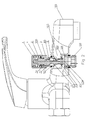
- This embodiment is the embodiment of the present invention that is used for faucet 100.
- the present invention includes water inlet piping inlet 101 and two water outlet piping outlets 103 and 104, that are comprised in a water diverting device.
- the two water outlet piping outlets of the water diverting device are provided with respectively upper sealing seat 102 and lower sealing seat 105 (see Fig. 2 in particular for this reference).
- the water diverting device is fitted with a water diverting switch that fits with the sealing seats and is used to switch over between the two outlets 103 and 104.
- the water diverting switch includes a fixed base 3 connected with the inlet 101 and outlet (103, 104) pipelines.
- the water diverting switch also has a sliding shaft 2 and there is a sliding through hole 31 of the sliding shaft 2 on the fixed base 3. A head 21 of the sliding shaft 2 is inserted into and extends beyond the sliding through hole 31.
- a tail of the sliding shaft 2 is connected with a button 1 at tail threads of the sliding shaft 2.
- the switch has a spring 4 pushing the connection of the button 1 and the sliding shaft 2 along a direction from head 21 of the sliding shaft 2 towards its tail.
- the spring 4 is located between the fixed base 3 and the button 1.
- the sliding shaft head 21 is connected with a valve core 20, and the positions of the above-mentioned upper sealing seat 102 and lower sealing seat 105 correspond with the movement distance of the valve core 20.
- the water outlet 104 is under the sealing seat 105.
- Item 23 in Fig. 1 is a sealing gasket mounted on the valve core 20.
- the spring 4 may be at any position where the sliding shaft 2 is able to obtain a force for moving from the head to the tail.
- Item 106 in Fig. 1 is a seal ring mounted on the sliding shaft 2 between the sliding shaft and the fixed base 3.
- Item 107 in Fig. 1 is a seal ring mounted between the fixed base 3 and the faucet 100.
- the water diverting switch is provided with a retaining hook 6 for the sliding shaft 2.
- the retaining hook 6 is connected on the fixed base 3.
- the retaining hook 6 can also be connected on a part connected with the fixed base 3.
- first stop position 71 and a second stop position 72 fitting with a hook part 60 of the retaining hook 6, and the first stop position 71 and second stop position 72 are located at different heights on the sliding shaft 2, with the first stop position 71 close to the head 21 of the sliding shaft 2.
- first unidirectional slide channel for the hook part of the retaining hook 6. The first unidirectional slide channel lets the sliding shaft 2 move from the state where the first stop position 71 is fitting with the hook part 60 of the retaining hook 6 to the state where the second stop position 72 is fitting with the hook part 60 of the retaining hook 6.
- the second unidirectional slide channel lets the sliding shaft 2 move from the state where the second stop position 72 is fitting with the hook part 60 of the retaining hook 6 to the state where the first stop position 71 is fitting with the hook part 60 of the retaining hook 6.
- the first unidirectional slide channel consists of a first slide way section 81 starting at the first stop position 71 and a second slide-way 82 connected with the first slide way section 81 and leading to the second stop position 72, whereby the connection from the second slide-way 82 with the first slide-way section 81 is located farther away from the head 21 of the sliding shaft 2 than the second stop position 72.
- the second unidirectional slide channel consists of a third slide way section 83 starting at the second stop position 72 and a fourth slide way section 84 connected with the third slide way section 83, whereby the connection from the fourth slide-way section 84 with the third slide-way section 83 is located farther away from the head 21 of the sliding shaft 2 than the second stop position 72, and the fourth slide way section 84 is connected with the first slide way section 81 or connected to the first stop position 71.
- Relative unidirectional slide movement between the first and the second unidirectional slide channels, and the hook part 60 can be provided through a slide channel design on a wall of the first and the second unidirectional slide channels, or a slide channel design on a bottom of the first and the second unidirectional slide channels.
- such relative unidirectional slide movement is provided through the design of the slide channel on the bottom, so that the switch has higher operation reliability and longer service life.
- Its design scheme is as follows: the first slide way section 81 and second slide way section 82 are connected in the form of a step, and at a connection 91, a channel bottom of the second slide way section 82 is lower than that of the first slide way section 81.
- the third slide way section 83 and fourth slide way section 84 are connected in the form of a step, and at a connection 92, a channel bottom of the fourth slide way section 84 is lower than that of the third slide way section 83.
- the second slide way section 82 has a down step 93 near the second stop position 72.
- the fourth slide way section 84 and first slide way section 81 are connected in the form of a step, and at a connection 94, a channel bottom of the first slide way section 81 is lower than that of the fourth slide way section 84.
- This embodiment fits with the immovable slide way on sliding shaft 2 through swinging of the hook part 60 of the retaining hook 6.
- the sliding shaft 2 has a positioning sliding channel 22 (see Fig. 3 ) in the axial direction and the fixed base 3 has a protruding positioning block part 32 whose shape can be used to fit with the retaining hook 6, as shown in Figs. 1 and 2 .
- the retaining hook 6 is connected by hooking to the protruding positioning part 32 of the fixed base 3.
- a circumferential positioning mechanism can also be the positioning channel that is provided in other position on the fixed base 3, such as an inner hole.
- the protruding positioning part 32 of the fixed base 3 is positioned at an other corresponding position on the sliding shaft 2.
- the circumferential positioning mechanism can also be any other common circumferential positioning mechanism between shaft and sleeve or provide corresponding positioning function by means of a device.
- the sliding shaft 2 can also be used to rotate by a specified angle to provide a fit between the slide way and retaining hook 6, but it is not as convenient and comfortable in use as in the embodiment of Figs. 1-4 .
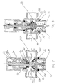
- a pressure force is applied on the button 1, and the button 1 drives the sliding shaft 2 to move down towards the sealing seat 105.
- the hook end 60 of retaining hook 6 is positioned on the fixed base 3 by the ring spring 5.
- the hook part 60 of the retaining hook 6 moves up the first slide way section 81 from the first stop position 71.
- the hook part 60 of the retaining hook 6 moves into a second hook part at the connection 91.
- the button 1 and the sliding shaft 2 move up under the action of spring 4, but as the first slide way section 81 and second slide way section 82 are connected in the form of a step, and at the connection 91, the channel bottom surface of the second slide way section 82 is lower than that of the first slide way section 81, the hook part 60 of the retaining hook 6 cannot move back on the original way and can only move to the second stop position 72 area on second slide way section 82 to connect with a vector point of the second stop position 72, which is a state position of the switch and provides downward travel of the sliding shaft.
- the spring 4 is compressed and sealing gasket 23 on the valve core 20 gets into contact with the lower sealing seat 105.
- the lower water outlet 104 is in sealing state, and the water diverting device is in upper water dispensing state, and water flows out of the outlet 103.
- the hook part 60 of the retaining hook 6 cannot move back on the original way and can only move down to the first stop position 71 along the fourth slide way section 84 or move down into the first slide way section 81 along the fourth slide way section 84 and finally returns to the first stop position 71 and connect with the first stop position 71, which is another state position of the switch and finishes upward movement of the sliding shaft 2.
- sealing gasket 23 on the valve core 20 gets into contact with the sealing seat 102.
- the upper water outlet 103 is in sealing state, and the water diverting device is in lower water dispensing state and water flows out of the outlet 104.
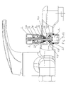
- the fixed base 3 in Embodiment 1 can also be formed by some parts connected with each other.
- the fixed base includes a mounting piece 33 and a connection sleeve 34 connected with its rear part.
- the connection sleeve 34 is connected with the water inlet pipeline 102 and water outlet pipelines 103 and 104.
- the sliding shaft 2 is smaller near its tail or between its middle and tail and goes through the connection sleeve 34.
- the connection sleeve 34 has a small hole 35 that fits with the smaller part of the sliding shaft 2.
- the retaining hook 6 is connected to the mounting piece 33.
- a ring spring for fixing the retaining hook 6 is provided on outer side of the mounting piece 33.
- the seal ring 106 as known from Embodiment 1 can be mounted on the smaller part of the sliding shaft 2 in Embodiment 2, and is connected under sealing condition with the small hole 35 on the connection sleeve 34 in order to reduce sliding resistance.
- this present invention is installed on the water diverter.
- the same water diverting device as in Embodiment 2 is used in this embodiment.
Landscapes
- Engineering & Computer Science (AREA)
- General Engineering & Computer Science (AREA)
- Public Health (AREA)
- Health & Medical Sciences (AREA)
- Life Sciences & Earth Sciences (AREA)
- Hydrology & Water Resources (AREA)
- Mechanical Engineering (AREA)
- Water Supply & Treatment (AREA)
- Sliding Valves (AREA)
- Multiple-Way Valves (AREA)
- Domestic Plumbing Installations (AREA)
- Sink And Installation For Waste Water (AREA)
- Mechanically-Actuated Valves (AREA)
- Lift Valve (AREA)
- Toys (AREA)
Applications Claiming Priority (1)
| Application Number | Priority Date | Filing Date | Title |
|---|---|---|---|
| CNB200710070337XA CN100570189C (zh) | 2007-07-26 | 2007-07-26 | 一种分水装置 |
Publications (3)
| Publication Number | Publication Date |
|---|---|
| EP2020547A2 true EP2020547A2 (fr) | 2009-02-04 |
| EP2020547A3 EP2020547A3 (fr) | 2010-09-08 |
| EP2020547B1 EP2020547B1 (fr) | 2016-04-27 |
Family
ID=38999259
Family Applications (1)
| Application Number | Title | Priority Date | Filing Date |
|---|---|---|---|
| EP08157506.0A Active EP2020547B1 (fr) | 2007-07-26 | 2008-06-03 | Dispositif de dérivation d'eau |
Country Status (10)
| Country | Link |
|---|---|
| US (1) | US8418720B2 (fr) |
| EP (1) | EP2020547B1 (fr) |
| JP (1) | JP3162157U (fr) |
| KR (1) | KR101212381B1 (fr) |
| CN (1) | CN100570189C (fr) |
| AU (1) | AU2008280766B2 (fr) |
| ES (1) | ES2584230T3 (fr) |
| PL (1) | PL2020547T3 (fr) |
| RU (1) | RU2455544C2 (fr) |
| WO (1) | WO2009012639A1 (fr) |
Cited By (1)
| Publication number | Priority date | Publication date | Assignee | Title |
|---|---|---|---|---|
| EP3147413A1 (fr) * | 2015-09-25 | 2017-03-29 | Xiamen Runner Industrial Corporation | Structure de mini route maritime |
Families Citing this family (22)
| Publication number | Priority date | Publication date | Assignee | Title |
|---|---|---|---|---|
| CN100570189C (zh) * | 2007-07-26 | 2009-12-16 | 宁波搏盛阀门管件有限公司 | 一种分水装置 |
| CN101846196A (zh) * | 2010-05-28 | 2010-09-29 | 邝松铭 | 一种暗装式自动分水器 |
| CN102678975A (zh) * | 2012-05-22 | 2012-09-19 | 郭华炎 | 一种拉帽式水龙头 |
| CN103307311B (zh) * | 2013-06-30 | 2015-12-09 | 开平诺迪水暖器材有限公司 | 一种用于卫浴水龙头的自动分水结构 |
| CN104696896B (zh) * | 2013-12-04 | 2019-11-12 | 海洋王(东莞)照明科技有限公司 | 锁扣连接结构及灯具 |
| CN104923419B (zh) * | 2015-06-12 | 2017-03-29 | 福建欣宇卫浴科技股份有限公司 | 一种顶喷花洒按键切换结构及其应用的顶喷花洒 |
| CN105864457B (zh) * | 2016-06-23 | 2018-10-26 | 佛山市法恩洁具有限公司 | 一种分水切换龙头 |
| CN106135116A (zh) * | 2016-08-16 | 2016-11-23 | 成都睿美水族用品有限公司 | 一种密封性能高的水族箱水循环控制开关 |
| GB2568271B (en) * | 2017-11-09 | 2020-04-22 | Kohler Mira Ltd | A plumbing component for controlling the mixture of two supplies of water |
| CN108150674A (zh) * | 2017-12-31 | 2018-06-12 | 上饶市圣麦司洁具制造有限公司 | 一种可接驳及切换出水方向的水嘴组件 |
| US10935146B2 (en) * | 2019-05-07 | 2021-03-02 | Purity (Xiamen) Sanitary Ware Co., Ltd. | T-joint having push-button switch |
| CN110285237B (zh) * | 2019-06-13 | 2024-08-27 | 日丰企业集团有限公司 | 淋浴器材及其分水装置 |
| RU198602U1 (ru) * | 2020-03-10 | 2020-07-20 | Федеральное государственное бюджетное образовательное учреждение высшего образования "Пензенский государственный технологический университет" | Пневмораспределитель клапанный с электромагнитным управлением |
| RU198769U1 (ru) * | 2020-03-10 | 2020-07-28 | Федеральное государственное бюджетное образовательное учреждение высшего образования "Пензенский государственный технологический университет" | Клапанный пневматический распределитель с электромагнитным управлением |
| DE202020101990U1 (de) * | 2020-04-09 | 2021-07-12 | Neoperl Gmbh | Umstellervorrichtung, Baureihe von Umstellervorrichtungen und Verwendung einer einheitlichen Schnittstelle zur Befestigung unterschiedlicher Varianten von Umstellervorrichtungen |
| CN111663615B (zh) * | 2020-06-24 | 2024-09-27 | 福建西河卫浴科技有限公司 | 一种起泡装置和相关的出水装置 |
| CN111911706B (zh) * | 2020-08-18 | 2025-02-14 | 福建省德牧卫浴科技有限公司 | 一种翘板按压结构及出水器 |
| CN112032347B (zh) * | 2020-09-08 | 2025-02-18 | 福建省德牧卫浴科技有限公司 | 一种按压阀及出水龙头 |
| KR102450892B1 (ko) * | 2021-03-17 | 2022-10-06 | 케이제이바스컬렉션 주식회사 | 조립식 수전 |
| CN114151574B (zh) * | 2021-12-06 | 2025-08-15 | 开平市易洁卫浴有限公司 | 一种多功能水龙头 |
| CN114962370B (zh) * | 2022-04-02 | 2023-09-22 | 山东临工工程机械有限公司 | 双向可变阻尼单向阀 |
| CN118623041A (zh) * | 2024-07-23 | 2024-09-10 | 厦门市得尔美卫浴有限公司 | 一种阀芯 |
Family Cites Families (30)
| Publication number | Priority date | Publication date | Assignee | Title |
|---|---|---|---|---|
| US1095295A (en) * | 1913-05-22 | 1914-05-05 | Merton P Stevens | Gas-burner valve. |
| US2277837A (en) * | 1939-10-14 | 1942-03-31 | Phillips Petroleum Co | Automatic switching valve |
| US2219105A (en) * | 1940-02-08 | 1940-10-22 | Keystone Brass & Rubber Co | Diverter valve |
| US2592361A (en) * | 1950-10-26 | 1952-04-08 | Shakespeare Products Co | Remote control device for heaters, valves, and other remote controlled parts |
| DE1750380A1 (de) * | 1968-04-26 | 1971-02-25 | Vaillant Joh Kg | Drucktasten-Umschaltventil |
| JPS5211424B1 (fr) * | 1971-03-27 | 1977-03-31 | ||
| BE789807A (fr) * | 1971-11-10 | 1973-04-06 | Fonderie Soc Gen De | Inverseur pour systeme de bain-douche |
| SU414438A1 (fr) * | 1972-06-14 | 1974-02-05 | ||
| IT1172979B (it) * | 1984-01-06 | 1987-06-18 | Giuliano Gnutti | Perfezionamento ai mezzi di comando meccanico di dispositivi valvolari, in particolare ma non esclucivamente per estintori e simili, del tipo a "valvola a sfera" |
| JPS61243619A (ja) * | 1985-04-19 | 1986-10-29 | アルプス電気株式会社 | ハ−トカム |
| FR2616265B1 (fr) * | 1987-06-05 | 1993-05-14 | Telemecanique Electrique | Interrupteur a accrochage |
| JPH01119132U (fr) * | 1988-02-08 | 1989-08-11 | ||
| US4982762A (en) * | 1989-03-15 | 1991-01-08 | Deere & Company | Hydraulic lift with weight transfer |
| RU2011090C1 (ru) * | 1989-11-21 | 1994-04-15 | Белорусская государственная политехническая академия | Трехходовой регулирующий клапан |
| US5094200A (en) * | 1991-05-28 | 1992-03-10 | Ford Motor Company | Lightweight composite engine valve |
| CN2132883Y (zh) * | 1992-07-15 | 1993-05-12 | 张兼程 | 双出水口浮球阀 |
| JPH0762698A (ja) * | 1993-08-27 | 1995-03-07 | Ube Ind Ltd | 浄水器用水路切換装置 |
| JP3202515B2 (ja) * | 1995-01-06 | 2001-08-27 | 株式会社東海理化電機製作所 | プッシュロックスイッチ |
| CN1140812A (zh) * | 1995-07-18 | 1997-01-22 | 沈仲山 | 摆控式多段龙头开关 |
| CN2241801Y (zh) * | 1995-08-17 | 1996-12-04 | 杨永祥 | 三通阀 |
| CN2263236Y (zh) * | 1996-03-19 | 1997-09-24 | 郭燊垠 | 莲蓬头出水切换开关 |
| US5608928A (en) | 1996-06-03 | 1997-03-11 | Wang; Wen-Mu | Faucet of a sink |
| US5813436A (en) | 1997-07-07 | 1998-09-29 | Chen; Chiao-Lin | Faucet device |
| US7213616B2 (en) * | 2003-09-02 | 2007-05-08 | Parker-Hannifin | Diversion valve fluid coupling |
| CN2660260Y (zh) * | 2003-10-10 | 2004-12-01 | 郭柏胜 | 一种水嘴式分水装置 |
| US6973937B1 (en) * | 2004-08-09 | 2005-12-13 | Tsai Chen Yang | Valve device for faucet or spray gun |
| CN1940363A (zh) * | 2005-09-28 | 2007-04-04 | 黄作兴 | 高加旁路阀 |
| GB0615925D0 (en) * | 2006-08-10 | 2006-09-20 | Williamson Robert | Improvements in or relating to tap adaptors |
| CN100549482C (zh) * | 2007-07-26 | 2009-10-14 | 宁波搏盛阀门管件有限公司 | 厨卫设施的开关 |
| CN100570189C (zh) * | 2007-07-26 | 2009-12-16 | 宁波搏盛阀门管件有限公司 | 一种分水装置 |
-
2007
- 2007-07-26 CN CNB200710070337XA patent/CN100570189C/zh active Active
-
2008
- 2008-02-13 JP JP2010600025U patent/JP3162157U/ja not_active Expired - Lifetime
- 2008-02-13 AU AU2008280766A patent/AU2008280766B2/en not_active Ceased
- 2008-02-13 WO PCT/CN2008/000342 patent/WO2009012639A1/fr not_active Ceased
- 2008-02-13 RU RU2010107032/06A patent/RU2455544C2/ru not_active IP Right Cessation
- 2008-02-13 KR KR1020107002362A patent/KR101212381B1/ko not_active Expired - Fee Related
- 2008-06-03 ES ES08157506.0T patent/ES2584230T3/es active Active
- 2008-06-03 EP EP08157506.0A patent/EP2020547B1/fr active Active
- 2008-06-03 PL PL08157506.0T patent/PL2020547T3/pl unknown
- 2008-07-21 US US12/219,362 patent/US8418720B2/en active Active
Non-Patent Citations (1)
| Title |
|---|
| None |
Cited By (1)
| Publication number | Priority date | Publication date | Assignee | Title |
|---|---|---|---|---|
| EP3147413A1 (fr) * | 2015-09-25 | 2017-03-29 | Xiamen Runner Industrial Corporation | Structure de mini route maritime |
Also Published As
| Publication number | Publication date |
|---|---|
| AU2008280766B2 (en) | 2012-11-08 |
| US8418720B2 (en) | 2013-04-16 |
| AU2008280766A1 (en) | 2009-01-29 |
| US20090025813A1 (en) | 2009-01-29 |
| PL2020547T3 (pl) | 2016-12-30 |
| RU2010107032A (ru) | 2011-09-10 |
| WO2009012639A1 (fr) | 2009-01-29 |
| ES2584230T3 (es) | 2016-09-26 |
| KR101212381B1 (ko) | 2012-12-13 |
| EP2020547B1 (fr) | 2016-04-27 |
| CN101105234A (zh) | 2008-01-16 |
| EP2020547A3 (fr) | 2010-09-08 |
| JP3162157U (ja) | 2010-08-26 |
| KR20100043205A (ko) | 2010-04-28 |
| RU2455544C2 (ru) | 2012-07-10 |
| CN100570189C (zh) | 2009-12-16 |
Similar Documents
| Publication | Publication Date | Title |
|---|---|---|
| US8418720B2 (en) | Water diverting device | |
| US8403297B2 (en) | Switch for kitchen and bath appliances | |
| US9707574B2 (en) | Diverter valve assembly and shower system | |
| CN106051208B (zh) | 切换阀单元、流体开关和流体开关的套件 | |
| CN103511661B (zh) | 一种组合先导阀结构及其应用该结构的淋浴系统 | |
| US9255388B2 (en) | Switch structure of water outlet of wall-mounted faucet | |
| US7231866B2 (en) | Opening and closing switch structure for valve pin control of gas cylinder | |
| US8857471B2 (en) | Control structure of wall-mounted faucet | |
| CN201809839U (zh) | 一种具有补气结构的气动按钮 | |
| US10443218B2 (en) | Faucets providing mixed water and air flow | |
| CN110440044B (zh) | 一种喷头复位装置及抽拉龙头 | |
| US9790667B2 (en) | Push-activated tub spout | |
| CN206072416U (zh) | 切换阀单元、流体开关和流体开关的套件 | |
| CN210146289U (zh) | 控水开关及喷枪、花洒 | |
| CN201081030Y (zh) | 一种分水装置 | |
| CN219450932U (zh) | 一种按压式台控 | |
| CA2990926C (fr) | Robinets fournissant le melange d'ecoulement d'eau et d'air | |
| CN104337402A (zh) | 一种隐藏式伸缩水龙头 | |
| CN102644774B (zh) | 一种浴缸龙头用低压快速溢流出水装置 | |
| CN102409737A (zh) | 具有补气结构的气动按钮 | |
| WO2015162394A1 (fr) | Garniture de robinet |
Legal Events
| Date | Code | Title | Description |
|---|---|---|---|
| PUAI | Public reference made under article 153(3) epc to a published international application that has entered the european phase |
Free format text: ORIGINAL CODE: 0009012 |
|
| AK | Designated contracting states |
Kind code of ref document: A2 Designated state(s): AT BE BG CH CY CZ DE DK EE ES FI FR GB GR HR HU IE IS IT LI LT LU LV MC MT NL NO PL PT RO SE SI SK TR |
|
| AX | Request for extension of the european patent |
Extension state: AL BA MK RS |
|
| PUAL | Search report despatched |
Free format text: ORIGINAL CODE: 0009013 |
|
| AK | Designated contracting states |
Kind code of ref document: A3 Designated state(s): AT BE BG CH CY CZ DE DK EE ES FI FR GB GR HR HU IE IS IT LI LT LU LV MC MT NL NO PL PT RO SE SI SK TR |
|
| AX | Request for extension of the european patent |
Extension state: AL BA MK RS |
|
| RIC1 | Information provided on ipc code assigned before grant |
Ipc: F16K 11/044 20060101AFI20081113BHEP Ipc: E03C 1/02 20060101ALI20100730BHEP |
|
| 17P | Request for examination filed |
Effective date: 20110302 |
|
| AKX | Designation fees paid |
Designated state(s): AT BE BG CH CY CZ DE DK EE ES FI FR GB GR HR HU IE IS IT LI LT LU LV MC MT NL NO PL PT RO SE SI SK TR |
|
| 17Q | First examination report despatched |
Effective date: 20140710 |
|
| GRAP | Despatch of communication of intention to grant a patent |
Free format text: ORIGINAL CODE: EPIDOSNIGR1 |
|
| INTG | Intention to grant announced |
Effective date: 20151112 |
|
| GRAS | Grant fee paid |
Free format text: ORIGINAL CODE: EPIDOSNIGR3 |
|
| GRAA | (expected) grant |
Free format text: ORIGINAL CODE: 0009210 |
|
| AK | Designated contracting states |
Kind code of ref document: B1 Designated state(s): AT BE BG CH CY CZ DE DK EE ES FI FR GB GR HR HU IE IS IT LI LT LU LV MC MT NL NO PL PT RO SE SI SK TR |
|
| REG | Reference to a national code |
Ref country code: GB Ref legal event code: FG4D |
|
| REG | Reference to a national code |
Ref country code: CH Ref legal event code: EP |
|
| REG | Reference to a national code |
Ref country code: AT Ref legal event code: REF Ref document number: 795189 Country of ref document: AT Kind code of ref document: T Effective date: 20160515 |
|
| REG | Reference to a national code |
Ref country code: IE Ref legal event code: FG4D |
|
| REG | Reference to a national code |
Ref country code: DE Ref legal event code: R096 Ref document number: 602008043837 Country of ref document: DE |
|
| REG | Reference to a national code |
Ref country code: FR Ref legal event code: PLFP Year of fee payment: 9 |
|
| REG | Reference to a national code |
Ref country code: LT Ref legal event code: MG4D |
|
| REG | Reference to a national code |
Ref country code: NL Ref legal event code: MP Effective date: 20160427 |
|
| REG | Reference to a national code |
Ref country code: AT Ref legal event code: MK05 Ref document number: 795189 Country of ref document: AT Kind code of ref document: T Effective date: 20160427 |
|
| REG | Reference to a national code |
Ref country code: ES Ref legal event code: FG2A Ref document number: 2584230 Country of ref document: ES Kind code of ref document: T3 Effective date: 20160926 |
|
| PG25 | Lapsed in a contracting state [announced via postgrant information from national office to epo] |
Ref country code: NL Free format text: LAPSE BECAUSE OF FAILURE TO SUBMIT A TRANSLATION OF THE DESCRIPTION OR TO PAY THE FEE WITHIN THE PRESCRIBED TIME-LIMIT Effective date: 20160427 |
|
| PG25 | Lapsed in a contracting state [announced via postgrant information from national office to epo] |
Ref country code: FI Free format text: LAPSE BECAUSE OF FAILURE TO SUBMIT A TRANSLATION OF THE DESCRIPTION OR TO PAY THE FEE WITHIN THE PRESCRIBED TIME-LIMIT Effective date: 20160427 Ref country code: LT Free format text: LAPSE BECAUSE OF FAILURE TO SUBMIT A TRANSLATION OF THE DESCRIPTION OR TO PAY THE FEE WITHIN THE PRESCRIBED TIME-LIMIT Effective date: 20160427 Ref country code: NO Free format text: LAPSE BECAUSE OF FAILURE TO SUBMIT A TRANSLATION OF THE DESCRIPTION OR TO PAY THE FEE WITHIN THE PRESCRIBED TIME-LIMIT Effective date: 20160727 |
|
| PG25 | Lapsed in a contracting state [announced via postgrant information from national office to epo] |
Ref country code: HR Free format text: LAPSE BECAUSE OF FAILURE TO SUBMIT A TRANSLATION OF THE DESCRIPTION OR TO PAY THE FEE WITHIN THE PRESCRIBED TIME-LIMIT Effective date: 20160427 Ref country code: AT Free format text: LAPSE BECAUSE OF FAILURE TO SUBMIT A TRANSLATION OF THE DESCRIPTION OR TO PAY THE FEE WITHIN THE PRESCRIBED TIME-LIMIT Effective date: 20160427 Ref country code: PT Free format text: LAPSE BECAUSE OF FAILURE TO SUBMIT A TRANSLATION OF THE DESCRIPTION OR TO PAY THE FEE WITHIN THE PRESCRIBED TIME-LIMIT Effective date: 20160829 Ref country code: SE Free format text: LAPSE BECAUSE OF FAILURE TO SUBMIT A TRANSLATION OF THE DESCRIPTION OR TO PAY THE FEE WITHIN THE PRESCRIBED TIME-LIMIT Effective date: 20160427 Ref country code: LV Free format text: LAPSE BECAUSE OF FAILURE TO SUBMIT A TRANSLATION OF THE DESCRIPTION OR TO PAY THE FEE WITHIN THE PRESCRIBED TIME-LIMIT Effective date: 20160427 Ref country code: GR Free format text: LAPSE BECAUSE OF FAILURE TO SUBMIT A TRANSLATION OF THE DESCRIPTION OR TO PAY THE FEE WITHIN THE PRESCRIBED TIME-LIMIT Effective date: 20160728 |
|
| PG25 | Lapsed in a contracting state [announced via postgrant information from national office to epo] |
Ref country code: BE Free format text: LAPSE BECAUSE OF FAILURE TO SUBMIT A TRANSLATION OF THE DESCRIPTION OR TO PAY THE FEE WITHIN THE PRESCRIBED TIME-LIMIT Effective date: 20160427 |
|
| REG | Reference to a national code |
Ref country code: DE Ref legal event code: R097 Ref document number: 602008043837 Country of ref document: DE |
|
| PG25 | Lapsed in a contracting state [announced via postgrant information from national office to epo] |
Ref country code: EE Free format text: LAPSE BECAUSE OF FAILURE TO SUBMIT A TRANSLATION OF THE DESCRIPTION OR TO PAY THE FEE WITHIN THE PRESCRIBED TIME-LIMIT Effective date: 20160427 Ref country code: CZ Free format text: LAPSE BECAUSE OF FAILURE TO SUBMIT A TRANSLATION OF THE DESCRIPTION OR TO PAY THE FEE WITHIN THE PRESCRIBED TIME-LIMIT Effective date: 20160427 Ref country code: DK Free format text: LAPSE BECAUSE OF FAILURE TO SUBMIT A TRANSLATION OF THE DESCRIPTION OR TO PAY THE FEE WITHIN THE PRESCRIBED TIME-LIMIT Effective date: 20160427 Ref country code: MC Free format text: LAPSE BECAUSE OF FAILURE TO SUBMIT A TRANSLATION OF THE DESCRIPTION OR TO PAY THE FEE WITHIN THE PRESCRIBED TIME-LIMIT Effective date: 20160427 Ref country code: RO Free format text: LAPSE BECAUSE OF FAILURE TO SUBMIT A TRANSLATION OF THE DESCRIPTION OR TO PAY THE FEE WITHIN THE PRESCRIBED TIME-LIMIT Effective date: 20160427 Ref country code: SK Free format text: LAPSE BECAUSE OF FAILURE TO SUBMIT A TRANSLATION OF THE DESCRIPTION OR TO PAY THE FEE WITHIN THE PRESCRIBED TIME-LIMIT Effective date: 20160427 |
|
| REG | Reference to a national code |
Ref country code: CH Ref legal event code: PL |
|
| PLBE | No opposition filed within time limit |
Free format text: ORIGINAL CODE: 0009261 |
|
| STAA | Information on the status of an ep patent application or granted ep patent |
Free format text: STATUS: NO OPPOSITION FILED WITHIN TIME LIMIT |
|
| GBPC | Gb: european patent ceased through non-payment of renewal fee |
Effective date: 20160727 |
|
| REG | Reference to a national code |
Ref country code: IE Ref legal event code: MM4A |
|
| 26N | No opposition filed |
Effective date: 20170130 |
|
| PG25 | Lapsed in a contracting state [announced via postgrant information from national office to epo] |
Ref country code: CH Free format text: LAPSE BECAUSE OF NON-PAYMENT OF DUE FEES Effective date: 20160630 Ref country code: LI Free format text: LAPSE BECAUSE OF NON-PAYMENT OF DUE FEES Effective date: 20160630 |
|
| PG25 | Lapsed in a contracting state [announced via postgrant information from national office to epo] |
Ref country code: SI Free format text: LAPSE BECAUSE OF FAILURE TO SUBMIT A TRANSLATION OF THE DESCRIPTION OR TO PAY THE FEE WITHIN THE PRESCRIBED TIME-LIMIT Effective date: 20160427 Ref country code: GB Free format text: LAPSE BECAUSE OF NON-PAYMENT OF DUE FEES Effective date: 20160727 Ref country code: IE Free format text: LAPSE BECAUSE OF NON-PAYMENT OF DUE FEES Effective date: 20160603 |
|
| REG | Reference to a national code |
Ref country code: FR Ref legal event code: PLFP Year of fee payment: 10 |
|
| PG25 | Lapsed in a contracting state [announced via postgrant information from national office to epo] |
Ref country code: CY Free format text: LAPSE BECAUSE OF FAILURE TO SUBMIT A TRANSLATION OF THE DESCRIPTION OR TO PAY THE FEE WITHIN THE PRESCRIBED TIME-LIMIT Effective date: 20160427 Ref country code: HU Free format text: LAPSE BECAUSE OF FAILURE TO SUBMIT A TRANSLATION OF THE DESCRIPTION OR TO PAY THE FEE WITHIN THE PRESCRIBED TIME-LIMIT; INVALID AB INITIO Effective date: 20080603 |
|
| REG | Reference to a national code |
Ref country code: FR Ref legal event code: PLFP Year of fee payment: 11 |
|
| PG25 | Lapsed in a contracting state [announced via postgrant information from national office to epo] |
Ref country code: IS Free format text: LAPSE BECAUSE OF FAILURE TO SUBMIT A TRANSLATION OF THE DESCRIPTION OR TO PAY THE FEE WITHIN THE PRESCRIBED TIME-LIMIT Effective date: 20160427 Ref country code: LU Free format text: LAPSE BECAUSE OF NON-PAYMENT OF DUE FEES Effective date: 20160603 Ref country code: MT Free format text: LAPSE BECAUSE OF NON-PAYMENT OF DUE FEES Effective date: 20160630 |
|
| PG25 | Lapsed in a contracting state [announced via postgrant information from national office to epo] |
Ref country code: BG Free format text: LAPSE BECAUSE OF FAILURE TO SUBMIT A TRANSLATION OF THE DESCRIPTION OR TO PAY THE FEE WITHIN THE PRESCRIBED TIME-LIMIT Effective date: 20160427 |
|
| REG | Reference to a national code |
Ref country code: DE Ref legal event code: R082 Ref document number: 602008043837 Country of ref document: DE Representative=s name: HL KEMPNER PATENTANWAELTE, SOLICITORS (ENGLAND, DE Ref country code: DE Ref legal event code: R082 Ref document number: 602008043837 Country of ref document: DE Representative=s name: HL KEMPNER PATENTANWALT, RECHTSANWALT, SOLICIT, DE Ref country code: DE Ref legal event code: R082 Ref document number: 602008043837 Country of ref document: DE Representative=s name: HL KEMPNER PARTG MBB, DE |
|
| PGFP | Annual fee paid to national office [announced via postgrant information from national office to epo] |
Ref country code: FR Payment date: 20210610 Year of fee payment: 14 Ref country code: IT Payment date: 20210614 Year of fee payment: 14 |
|
| PGFP | Annual fee paid to national office [announced via postgrant information from national office to epo] |
Ref country code: PL Payment date: 20210525 Year of fee payment: 14 Ref country code: TR Payment date: 20210531 Year of fee payment: 14 |
|
| PGFP | Annual fee paid to national office [announced via postgrant information from national office to epo] |
Ref country code: ES Payment date: 20210716 Year of fee payment: 14 |
|
| PG25 | Lapsed in a contracting state [announced via postgrant information from national office to epo] |
Ref country code: FR Free format text: LAPSE BECAUSE OF NON-PAYMENT OF DUE FEES Effective date: 20220630 |
|
| REG | Reference to a national code |
Ref country code: ES Ref legal event code: FD2A Effective date: 20230726 |
|
| PG25 | Lapsed in a contracting state [announced via postgrant information from national office to epo] |
Ref country code: IT Free format text: LAPSE BECAUSE OF NON-PAYMENT OF DUE FEES Effective date: 20220603 |
|
| PG25 | Lapsed in a contracting state [announced via postgrant information from national office to epo] |
Ref country code: ES Free format text: LAPSE BECAUSE OF NON-PAYMENT OF DUE FEES Effective date: 20220604 |
|
| PG25 | Lapsed in a contracting state [announced via postgrant information from national office to epo] |
Ref country code: PL Free format text: LAPSE BECAUSE OF NON-PAYMENT OF DUE FEES Effective date: 20220603 |
|
| PG25 | Lapsed in a contracting state [announced via postgrant information from national office to epo] |
Ref country code: TR Free format text: LAPSE BECAUSE OF NON-PAYMENT OF DUE FEES Effective date: 20220603 |
|
| PGFP | Annual fee paid to national office [announced via postgrant information from national office to epo] |
Ref country code: DE Payment date: 20250623 Year of fee payment: 18 |