EP2020548A1 - Ventil zur flammenlosen Entlastung - Google Patents
Ventil zur flammenlosen Entlastung Download PDFInfo
- Publication number
- EP2020548A1 EP2020548A1 EP20080161321 EP08161321A EP2020548A1 EP 2020548 A1 EP2020548 A1 EP 2020548A1 EP 20080161321 EP20080161321 EP 20080161321 EP 08161321 A EP08161321 A EP 08161321A EP 2020548 A1 EP2020548 A1 EP 2020548A1
- Authority
- EP
- European Patent Office
- Prior art keywords
- conduit
- housing
- engagement member
- initiator
- relief valve
- Prior art date
- Legal status (The legal status is an assumption and is not a legal conclusion. Google has not performed a legal analysis and makes no representation as to the accuracy of the status listed.)
- Withdrawn
Links
Images


Classifications
-
- F—MECHANICAL ENGINEERING; LIGHTING; HEATING; WEAPONS; BLASTING
- F16—ENGINEERING ELEMENTS AND UNITS; GENERAL MEASURES FOR PRODUCING AND MAINTAINING EFFECTIVE FUNCTIONING OF MACHINES OR INSTALLATIONS; THERMAL INSULATION IN GENERAL
- F16K—VALVES; TAPS; COCKS; ACTUATING-FLOATS; DEVICES FOR VENTING OR AERATING
- F16K13/00—Other constructional types of cut-off apparatus; Arrangements for cutting-off
- F16K13/04—Other constructional types of cut-off apparatus; Arrangements for cutting-off with a breakable closure member
- F16K13/06—Other constructional types of cut-off apparatus; Arrangements for cutting-off with a breakable closure member constructed to be ruptured by an explosion
-
- B—PERFORMING OPERATIONS; TRANSPORTING
- B60—VEHICLES IN GENERAL
- B60H—ARRANGEMENTS OF HEATING, COOLING, VENTILATING OR OTHER AIR-TREATING DEVICES SPECIALLY ADAPTED FOR PASSENGER OR GOODS SPACES OF VEHICLES
- B60H1/00—Heating, cooling or ventilating devices
- B60H1/00642—Control systems or circuits; Control members or indication devices for heating, cooling or ventilating devices
- B60H1/00978—Control systems or circuits characterised by failure of detection or safety means; Diagnostic methods
-
- F—MECHANICAL ENGINEERING; LIGHTING; HEATING; WEAPONS; BLASTING
- F16—ENGINEERING ELEMENTS AND UNITS; GENERAL MEASURES FOR PRODUCING AND MAINTAINING EFFECTIVE FUNCTIONING OF MACHINES OR INSTALLATIONS; THERMAL INSULATION IN GENERAL
- F16L—PIPES; JOINTS OR FITTINGS FOR PIPES; SUPPORTS FOR PIPES, CABLES OR PROTECTIVE TUBING; MEANS FOR THERMAL INSULATION IN GENERAL
- F16L41/00—Branching pipes; Joining pipes to walls
- F16L41/04—Tapping pipe walls, i.e. making connections through the walls of pipes while they are carrying fluids; Fittings therefor
- F16L41/06—Tapping pipe walls, i.e. making connections through the walls of pipes while they are carrying fluids; Fittings therefor making use of attaching means embracing the pipe
-
- F—MECHANICAL ENGINEERING; LIGHTING; HEATING; WEAPONS; BLASTING
- F25—REFRIGERATION OR COOLING; COMBINED HEATING AND REFRIGERATION SYSTEMS; HEAT PUMP SYSTEMS; MANUFACTURE OR STORAGE OF ICE; LIQUEFACTION SOLIDIFICATION OF GASES
- F25B—REFRIGERATION MACHINES, PLANTS OR SYSTEMS; COMBINED HEATING AND REFRIGERATION SYSTEMS; HEAT PUMP SYSTEMS
- F25B49/00—Arrangement or mounting of control or safety devices
- F25B49/005—Arrangement or mounting of control or safety devices of safety devices
-
- F—MECHANICAL ENGINEERING; LIGHTING; HEATING; WEAPONS; BLASTING
- F25—REFRIGERATION OR COOLING; COMBINED HEATING AND REFRIGERATION SYSTEMS; HEAT PUMP SYSTEMS; MANUFACTURE OR STORAGE OF ICE; LIQUEFACTION SOLIDIFICATION OF GASES
- F25B—REFRIGERATION MACHINES, PLANTS OR SYSTEMS; COMBINED HEATING AND REFRIGERATION SYSTEMS; HEAT PUMP SYSTEMS
- F25B2345/00—Details for charging or discharging refrigerants; Service stations therefor
- F25B2345/006—Details for charging or discharging refrigerants; Service stations therefor characterised by charging or discharging valves
-
- F—MECHANICAL ENGINEERING; LIGHTING; HEATING; WEAPONS; BLASTING
- F25—REFRIGERATION OR COOLING; COMBINED HEATING AND REFRIGERATION SYSTEMS; HEAT PUMP SYSTEMS; MANUFACTURE OR STORAGE OF ICE; LIQUEFACTION SOLIDIFICATION OF GASES
- F25B—REFRIGERATION MACHINES, PLANTS OR SYSTEMS; COMBINED HEATING AND REFRIGERATION SYSTEMS; HEAT PUMP SYSTEMS
- F25B2500/00—Problems to be solved
- F25B2500/22—Preventing, detecting or repairing leaks of refrigeration fluids
- F25B2500/222—Detecting refrigerant leaks
-
- F—MECHANICAL ENGINEERING; LIGHTING; HEATING; WEAPONS; BLASTING
- F25—REFRIGERATION OR COOLING; COMBINED HEATING AND REFRIGERATION SYSTEMS; HEAT PUMP SYSTEMS; MANUFACTURE OR STORAGE OF ICE; LIQUEFACTION SOLIDIFICATION OF GASES
- F25B—REFRIGERATION MACHINES, PLANTS OR SYSTEMS; COMBINED HEATING AND REFRIGERATION SYSTEMS; HEAT PUMP SYSTEMS
- F25B45/00—Arrangements for charging or discharging refrigerant
-
- Y—GENERAL TAGGING OF NEW TECHNOLOGICAL DEVELOPMENTS; GENERAL TAGGING OF CROSS-SECTIONAL TECHNOLOGIES SPANNING OVER SEVERAL SECTIONS OF THE IPC; TECHNICAL SUBJECTS COVERED BY FORMER USPC CROSS-REFERENCE ART COLLECTIONS [XRACs] AND DIGESTS
- Y10—TECHNICAL SUBJECTS COVERED BY FORMER USPC
- Y10T—TECHNICAL SUBJECTS COVERED BY FORMER US CLASSIFICATION
- Y10T137/00—Fluid handling
- Y10T137/1624—Destructible or deformable element controlled
- Y10T137/1632—Destructible element
- Y10T137/1647—Explosive actuation
Definitions
- Relief valves may be associated with a fluid conduit of a system to selectively vent a fluid disposed within the conduit.
- a relief valve may be associated with a conduit of a closed-loop system such as, for example, a refrigeration system that selectively vents a refrigerant disposed within the conduit should a leak be detected within the system.
- the relief valve may vent such a closed-loop system to allow the refrigerant disposed within the refrigeration system to escape and be directed away from occupants disposed within an area to be heated and/or cooled.
- Relief valves are currently being implemented in automotive heating, ventilation, and air conditioning (HVAC) systems to vent refrigerant contained within the automotive HVAC system, should a leak be detected anywhere within the system.
- HVAC heating, ventilation, and air conditioning
- the relief valve may be positioned within an engine compartment of a vehicle such that if a leak is detected, the relief valve vents the HVAC system and allows the refrigerant to escape into the engine compartment and away from a passenger compartment of the vehicle.
- conventional relief valves While conventional relief valves have proven to adequately vent refrigerant from closed-loop systems, such relief valves must be in fluid communication with a conduit of the closed-loop system and, therefore, increase the overall number of joints of the system. Increasing the number of joints of the system increases potential leak points and the overall cost of the system.
- conventional relief valves may include a pyrotechnic device that actuates a burst disk upon detection of a leak within the system to vent fluid disposed within the system. Actuation of such a pyrotechnic device utilizes the heat and pressure produced by the pyrotechnic device to facilitate opening of the burst disk.
- the present invention proposes to solve these problems.
- a first aspect of this invention relates to a relief valve for use with a conduit includes a housing attached to the conduit and an engagement member slidably disposed within the housing and movable between a retracted position and an extended position. The engagement member pierces the conduit when moved from the retracted position to the extended position.
- a further aspect of this invention concerns a closed loop system which includes a relief valve according to one of the preceding features.
- the invention also concerns a method comprising:
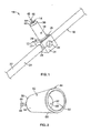
- a relief-valve assembly 10 is provided and includes a housing 12, an actuation device 14, and an engagement element 16.
- the relief-valve assembly 10 may be used with a conduit 18 and may selectively pierce the conduit 18 to vent a fluid disposed within the conduit 18.
- the conduit 18 may be a component of a closed-loop system such as, for example, a refrigeration system or a heating, ventilation, and air conditioning (HVAC) system, to carry and distribute refrigerant within the refrigeration system or HVAC system.
- HVAC heating, ventilation, and air conditioning
- the relief-valve assembly 10 will be described and shown in the drawings as being associated with a conduit 18 of a refrigeration system such as a HVAC system, the relief-valve assembly 10 of the present teachings could be used with any conduit to selectively vent a fluid disposed within the conduit.
- the term "fluid” refers to any fluid medium such as, but not limited to, a liquid and/or a gas.
- the housing 12 may include a unitary construction that is slidably received on an exterior surface 20 of the conduit 18.
- the housing 12 may include a multi-part construction that is matingly received by the conduit 18 and attached to the exterior surface 20. While the housing 12 may include a unitary construction or a multi-piece construction, the housing 12 will be described and shown hereinafter in the drawings as including a multi-part construction.
- the housing 12 includes a first half 22 and a second half 24 that are fixedly attached to one another by a plurality of fasteners 26 or any suitable attachment device.
- the conduit 18 is disposed generally between the first half 22 and the second half 24 when the first half 22 is attached to the second half 24 and is received within a first bore 28 of the housing 12.
- the first bore 28 extends generally along a length of the first half 22 and second half 24 and includes a diameter substantially equal to an outer diameter of the conduit 18 such that the conduit 18 is matingly received between the first half 22 and the second half 24 within the first bore 28.
- the fasteners 26 or other attachment device may be inserted into one or both of the first half 22 and second half 24 to engage the other of the first half 22 and second half 24 to fixedly attach the housing 12 to the conduit 18.
- the first bore 28 is described as including a diameter that is substantially equal to an outer diameter of the conduit 18, a surface 30 of the first bore 28 may engage the exterior surface 20 of the conduit 18 when the fasteners 26 are inserted in the first half 22 and second half 24 such that the first half 22 and second half 24 are clamped to the exterior surface 20 of the conduit 18. Clamping the first half 22 and second half 24 of the housing 12 to the exterior surface 20 of the conduit 18 prevents movement of the housing 12 relative to the conduit 18. Furthermore, while the housing 12 is attached to surface 20 of the conduit 18, the first bore 28 of the housing 12 is fluidly isolated from an interior 32 of the conduit 18.
- the housing 12 may further include a second bore 34 formed through the housing 12.
- the second bore may be substantially perpendicular to the first bore 28.
- the second bore 34 may extend across a length of the housing 12 or, alternatively, may only extend across a portion of the housing 12. In either configuration, the second bore 34 is in fluid communication with the first bore 28, but is fluidly isolated from the interior 32 of the conduit 18.
- An arm 36 extends generally from a junction of the first bore 28 and the second bore 34 and includes an opening 38 in fluid communication with the first bore 28 and a thin-walled section 40 disposed proximate to the opening 38.
- the first bore 28 extends along a length of the arm 36 from the opening 38 to the junction between the first bore 28 and the second bore 34.
- the arm 36 may be integrally formed with or fixedly attached to one of the first half 22 and second half 24. While the arm 36 may be integrally formed with or fixedly attached to one of the first half 22 and second half 24, the arm 36 will be described and shown in the drawings as being integrally formed with the first half 22 of the housing 12.
- the actuation device 14 is disposed within the first half 22 of the housing 12 generally within the arm 36 and includes an initiator 44 and a pyrotechnic charge 46 having a pair of leads 48 electrically coupled thereto.
- the pyrotechnic charge 46 may be ignited by supplying an electrical charge to the pyrotechnic charge 46 via at least one of the leads 48.
- the initiator 44 is disposed generally within the arm 36 between the pyrotechnic charge 46 and the engagement element 16 and includes a first end 50 disposed proximate to the pyrotechnic charge 46 and a second end 52 disposed adjacent to the engagement element 16.
- the first end 50 of the initiator 44 is open and may receive the pyrotechnic charge 46 therein such that the pyrotechnic charge 46 is disposed generally within an interior space of the initiator 44.
- the second end 52 of the initiator 44 is closed and includes an engagement surface 56 in an abutting relationship with the engagement element 16.
- the second end 52 of the initiator 44 is drawn into the interior space 54 of the initiator 44 and forms a cavity 58. At least a portion of the engagement element 16 is received within the cavity 58 of the initiator 44 and is in an abutting relationship with the engagement surface 56.
- the initiator 44 may be referred to as a "redrawn" initiator. While the second end 52 of the initiator 44 is redrawn such that the second end 52 is moved within the interior space 54 of the initiator 44 and towards the pyrotechnic charge 46, the interior space 54 of the initiator 44 is sealed generally between the pyrotechnic charge 46 and the second end 52. Therefore, when the pyrotechnic charge 46 is ignited, the byproduct of the pyrotechnic charge 46 is contained within the interior space 54 of the initiator 44 generally between the pyrotechnic charge 46 and the second end 52 of the initiator 44.
- the initiator 44 may include an outer diameter substantially equal to an inner diameter of the first bore 28 such that an outer surface 62 of the initiator 44 is in an abutting relationship with the inner surface 30 of the first bore 28.
- the initiator 44 may also be contained within the first bore 28 of the arm 36 by deforming the thin-walled section 40 of the arm 36 once the engagement element 16, and pyrotechnic charge 46 are disposed within the first bore 28 of the arm 36.
- the thin-walled section 40 may engage a housing 64 generally surrounding the pair of leads 48 to prevent removal of the initiator 44, pyrotechnic charge 46, and leads 48 from the first bore 28 of the housing 12.
- the engagement element 16 is slidably received within the first bore 28 of the arm 36 and includes a first end 66, a second end 68, and a central portion 70 disposed generally between the first end 66 and second end 68.
- the first end 66 is received within the cavity 58 of the initiator 44 such that the first end 66 is in an abutting relationship with the engagement surface 56 of the second end 52 of the initiator 44.
- the walls 60 of the initiator 44 at least partially axially surround the first end 66 of the engagement element 16 when the initiator 44 is in the pre-deployed state ( FIG. 3 ).
- the first end 66 may include a length that is substantially equal to a length of the cavity 58 such that the walls 60 of the initiator 44 engage a contact surface 72 of the engagement element 16.
- the contact surface 72 may be disposed at a junction between the first end 66 and the central portion 70 of the engagement element 16 and extends from the second end 68 substantially perpendicularly.
- the second end 68 is disposed on an opposite end of the engagement element 16 from the first end 66 and may include a cutting feature 74.
- the cutting feature 74 may include a sharped edge and/or an inclined surface that, when engaged with the conduit 18, pierces the conduit 18.
- the central portion 70 is disposed generally between the first end 66 and the second end 68 of the engagement element 16 and includes an outer diameter that is substantially equal to the inner diameter of the arm 36.
- the central portion 70 is slidingly received within the first bore 28 of the arm 36 to allow the engagement element 16 to translate relative to the housing 12 between a retracted position ( FIG. 3 ) and an extended position ( FIG. 5 ).
- the relative thickness of the first end 66 when compared to the central portion 70 defines a gap 71 ( FIG. 4 ) generally between an outer surface 78 of the first end 66 and the inner surface 30 of the first bore 28.
- the gap 71 formed between the outer surface 76 of the first end 66 and the surface 30 of the first bore 28 is substantially equal to two times a thickness of the walls 60 of the initiator 44.
- the second end 52 of the initiator 44 is in close proximity to the pyrotechnic charge 46 such that the cavity 58 is substantially filled with the first end 66 of the engagement element 16.
- the first end 66 of the engagement element 16 is in contact with the engagement surface 56 of the initiator 44.
- the contact surface 72 of the engagement element 16 is in contact with the walls 60 of the initiator 44 at a point where the walls 60 are redrawn.
- the engagement element 16 is spaced apart from or just in contact with the exterior surface 20 of the conduit 18.
- the interior 32 of the conduit 18 is fluidly isolated from the first bore 28 and second bore 34 of the housing 12 when the relief-valve assembly 10 is in the pre-deployed state.
- a force may be applied to the engagement element 16 to move the engagement element 16 from the retracted position ( FIG. 3 ) to the extended position ( FIG. 5 ) to contact and pierce the conduit 18. Movement of the engagement element 16 is accomplished by supplying an electrical charge to the pyrotechnic charge 46 via leads 48. The electrical charge ignites the pyrotechnic charge 46, thereby causing an increase in pressure within the interior space 54 of the initiator 44. The increase in pressure within the interior space 54 of the initiator 44 applies a force to the walls 60 of the initiator 44.
- the force applied to the walls 60 does not cause radial deformation of the walls 60 of the initiator 44, as the walls 60 are supported by the surface 30 of the first bore 28.
- the second end 52 is not supported by the surface 30 of the first bore 28 and is therefore moved relative to the arm 36 when the pressure within the interior space 54 is increased by initiation of the actuation device 14.
- Movement of the second end 52 of the initiator 44 relative to the arm 36 causes concurrent movement of the engagement element 16 relative to the arm 36 ( FIG. 4 ), as the engagement element 16 is in an abutting relationship with the second end 52 of the initiator 44.
- the relief-valve assembly 10 is shown incorporated into a HVAC system 80 of a vehicle 82.
- the HVAC system 80 includes the conduit 18 extending in a closed-loop fashion between a compressor 84, an evaporator 86, and a condenser 88.
- the relief-valve assembly 10 is positioned along the conduit 18 generally within an engine compartment 90 to prevent fluid communication of a fluid disposed within the conduit 18 with a passenger compartment 92 if the engagement element 16 pierces the conduit 18.
- the relief-valve assembly 10 may be in communication with a control module 94 such as a body controller 96 and/or a safety-system controller 98.
- the leads 48 are electrically coupled to the control module 94 to allow the control module 94 to selectively supply an electrical current to the pyrotechnic charge 46 via the leads 48 to control movement of the engagement element 16 from the retracted position to the extended position.
- control module 94 may be in communication with a sensor assembly that monitors operating parameters of the vehicle 82.
- the sensor assembly may include a refrigerant-detecting sensor 102 disposed within the passenger compartment 92 and/or an airbag sensor 104 that detects a vehicle crash event.
- control module 94 may be in communication with a refrigerant-detecting sensor 102 and/or an airbag sensor 104, operation of the relief-valve assembly 10 will be described in conjunction with a system including both a refrigerant-detecting sensor 102 and an airbag sensor 104.
- the control module 94 may send a signal to the pyrotechnic charge 46 to initiate the pyrotechnic charge 46 via the leads 48.
- supplying electrical charge to the leads 48 of the pyrotechnic charge 46 causes the pyrotechnic charge 46 to ignite and move the second end 52 of the initiator 44 relative to the arm 36.
- Such movement of the second end 52 of the initiator 44 relative to the arm 36 causes concurrent movement of the engagement element 16.
- Sufficient movement of the engagement element 16 relative to the arm 36 causes the engagement element 16 to pierce the conduit 18, thereby placing the interior 32 of the conduit 18 in fluid communication with the first bore 28 and the second bore 34 of the housing 12. Once the conduit 18 is pierced, fluid disposed within the conduit 18 is permitted to escape the conduit 18 and HVAC system 80 and related components 84, 86, 88 and vent through the second bore 34 of the housing 12.
- the control module 94 may similarly send a signal to the pyrotechnic charge 46 via the leads 48 to ignite the pyrotechnic charge 46 to cause movement of the initiator 44.
- movement of the second end 52 of the initiator 44 causes concurrent movement of the engagement element 16 relative to the arm 36 and causes the engagement element 16 to pierce the conduct 18.
- fluid was disposed within the conduit 18 and refrigerant and HVAC system 80 and related components 84, 86, 88 are vented into the engine compartment 90 of the vehicle 82 and are prevented from entering the passenger compartment 92.
- a tube 106 may be attached to the housing 12 at the second bore 34 to place the second bore 34 of the housing 12 in fluid communication with a particular area of the engine compartment 90.
- the tube 106 may extend from the second bore 34 of the housing 12 and to a wheel well 108, for example. Therefore, if the control module 94 causes the pyrotechnic charge 46 to fire and the engagement element 16 to pierce the conduit 18, refrigerant from the conduit 18 and HVAC system 80 will be vented to an area proximate the wheel well 108.
Landscapes
- Engineering & Computer Science (AREA)
- General Engineering & Computer Science (AREA)
- Mechanical Engineering (AREA)
- Physics & Mathematics (AREA)
- Thermal Sciences (AREA)
- Safety Valves (AREA)
Applications Claiming Priority (1)
| Application Number | Priority Date | Filing Date | Title |
|---|---|---|---|
| US11/832,678 US20090032113A1 (en) | 2007-08-02 | 2007-08-02 | Flameless relief valve |
Publications (1)
| Publication Number | Publication Date |
|---|---|
| EP2020548A1 true EP2020548A1 (de) | 2009-02-04 |
Family
ID=40001499
Family Applications (1)
| Application Number | Title | Priority Date | Filing Date |
|---|---|---|---|
| EP20080161321 Withdrawn EP2020548A1 (de) | 2007-08-02 | 2008-07-29 | Ventil zur flammenlosen Entlastung |
Country Status (2)
| Country | Link |
|---|---|
| US (1) | US20090032113A1 (de) |
| EP (1) | EP2020548A1 (de) |
Cited By (3)
| Publication number | Priority date | Publication date | Assignee | Title |
|---|---|---|---|---|
| AT516243A1 (de) * | 2014-08-26 | 2016-03-15 | Hirtenberger Automotive Safety | Pyrotechnische Trenneinrichtung für eine Klimaanlage |
| WO2016065286A1 (en) * | 2014-10-24 | 2016-04-28 | Key Safety Systems, Inc. | Tube cutter |
| AT516477A1 (de) * | 2014-10-31 | 2016-05-15 | Hirtenberger Automotive Safety | Pyrotechnisches Entlüftungselement |
Families Citing this family (4)
| Publication number | Priority date | Publication date | Assignee | Title |
|---|---|---|---|---|
| US8671967B2 (en) * | 2009-08-07 | 2014-03-18 | Autoliv Asp, Inc. | Relief valve |
| JP6375639B2 (ja) * | 2014-02-21 | 2018-08-22 | ダイキン工業株式会社 | 空気調和装置 |
| DE102015211928B3 (de) * | 2015-06-26 | 2016-05-25 | Bayerische Motoren Werke Aktiengesellschaft | Kältemittelablasseinrichtung für Fahrzeugklimatisierungseinrichtungen |
| DE102015212725A1 (de) * | 2015-07-08 | 2017-01-12 | Bayerische Motoren Werke Aktiengesellschaft | Kraftfahrzeug |
Citations (6)
| Publication number | Priority date | Publication date | Assignee | Title |
|---|---|---|---|---|
| DE877390C (de) * | 1951-07-17 | 1953-05-21 | Union Rheinische Braunkohlen | Schnelloeffnungsverschluss |
| US2959326A (en) * | 1959-05-04 | 1960-11-08 | Harvey N Pouliot | Fluid controlling means |
| US3495615A (en) * | 1967-07-27 | 1970-02-17 | Sealed Unit Parts Co Inc | Debrisless tap valve |
| US4111221A (en) * | 1976-01-28 | 1978-09-05 | Olsen Charles R | Low restriction, normally open valve construction having a deformable bladder |
| US4421005A (en) * | 1962-03-28 | 1983-12-20 | The United States Of America As Represented By The United States Department Of Energy | Explosive actuated valve |
| WO2007087992A1 (de) * | 2006-02-02 | 2007-08-09 | Thomas Magnete Gmbh | Expansionsventil für eine klimaanlage |
Family Cites Families (11)
| Publication number | Priority date | Publication date | Assignee | Title |
|---|---|---|---|---|
| US4409879A (en) * | 1961-12-27 | 1983-10-18 | Cobb Jr Lawrence L | Explosive actuated valves |
| US3404598A (en) * | 1966-12-30 | 1968-10-08 | Aai Corp | Cup-sealed actuator with obturating groove anchoring and sealing arrangement |
| BR7310655D0 (pt) * | 1973-12-20 | 1975-09-16 | Gebelius Sven Runo Vilhelm | Metodos de conexao de tubo para a conexao de tubos estendidos transversalmente a um tubo de transporte estendido longitudinalmente |
| US4478150A (en) * | 1983-01-12 | 1984-10-23 | The United States Of America As Represented By The Secretary Of The Army | Cartridge with elastic pusher cup |
| US4821775A (en) * | 1988-10-03 | 1989-04-18 | Us Sec Of The | One shot valve |
| IL105616A (en) * | 1993-05-05 | 1997-07-13 | Israel Benraft Ind Ltd | Squib valve |
| US5372071A (en) * | 1993-07-13 | 1994-12-13 | Tracor, Inc. | Thrusting separation system |
| US7044151B2 (en) * | 2001-01-16 | 2006-05-16 | Scot Incorporated | Piston-activated valve and methods and apparatus for restraining free play in a device |
| JP2003065453A (ja) * | 2001-08-28 | 2003-03-05 | Smc Corp | バルブ用ボディ及びその製造方法 |
| US6912860B2 (en) * | 2003-08-08 | 2005-07-05 | Delphi Technologies, Inc. | Method of operating a directed relief valve in an air conditioning system |
| US7373944B2 (en) * | 2004-12-27 | 2008-05-20 | Autoliv Asp, Inc. | Pyrotechnic relief valve |
-
2007
- 2007-08-02 US US11/832,678 patent/US20090032113A1/en not_active Abandoned
-
2008
- 2008-07-29 EP EP20080161321 patent/EP2020548A1/de not_active Withdrawn
Patent Citations (6)
| Publication number | Priority date | Publication date | Assignee | Title |
|---|---|---|---|---|
| DE877390C (de) * | 1951-07-17 | 1953-05-21 | Union Rheinische Braunkohlen | Schnelloeffnungsverschluss |
| US2959326A (en) * | 1959-05-04 | 1960-11-08 | Harvey N Pouliot | Fluid controlling means |
| US4421005A (en) * | 1962-03-28 | 1983-12-20 | The United States Of America As Represented By The United States Department Of Energy | Explosive actuated valve |
| US3495615A (en) * | 1967-07-27 | 1970-02-17 | Sealed Unit Parts Co Inc | Debrisless tap valve |
| US4111221A (en) * | 1976-01-28 | 1978-09-05 | Olsen Charles R | Low restriction, normally open valve construction having a deformable bladder |
| WO2007087992A1 (de) * | 2006-02-02 | 2007-08-09 | Thomas Magnete Gmbh | Expansionsventil für eine klimaanlage |
Cited By (4)
| Publication number | Priority date | Publication date | Assignee | Title |
|---|---|---|---|---|
| AT516243A1 (de) * | 2014-08-26 | 2016-03-15 | Hirtenberger Automotive Safety | Pyrotechnische Trenneinrichtung für eine Klimaanlage |
| AT516243B1 (de) * | 2014-08-26 | 2017-04-15 | Hirtenberger Automotive Safety Gmbh & Co Kg | Pyrotechnische Trenneinrichtung für eine Klimaanlage |
| WO2016065286A1 (en) * | 2014-10-24 | 2016-04-28 | Key Safety Systems, Inc. | Tube cutter |
| AT516477A1 (de) * | 2014-10-31 | 2016-05-15 | Hirtenberger Automotive Safety | Pyrotechnisches Entlüftungselement |
Also Published As
| Publication number | Publication date |
|---|---|
| US20090032113A1 (en) | 2009-02-05 |
Similar Documents
| Publication | Publication Date | Title |
|---|---|---|
| EP2020548A1 (de) | Ventil zur flammenlosen Entlastung | |
| KR100403948B1 (ko) | 가변 팽창 성능을 갖는 에어 백 모듈 및 에어백 모듈의 팽창율을 변경하기 위한 방법 | |
| JP5141386B2 (ja) | 作動ピンを有したアクチュエータ | |
| JP4243211B2 (ja) | 冷凍システム | |
| US7347448B2 (en) | Inflator device for airbag installations | |
| EP3228486B1 (de) | Sicherungsvorrichtung für ein fahrzeug | |
| EP2819890B1 (de) | Airbag mit mehrstufiger entlüftung | |
| JP2000233638A (ja) | 車両用空調装置の安全装置 | |
| US8671967B2 (en) | Relief valve | |
| US7444918B2 (en) | Pyrotechnic actuator | |
| JP3035831U (ja) | エアバッグのインフレータ | |
| EP1621376B1 (de) | Kältemittelentlastungsanlage | |
| EP3209921B1 (de) | Rohrschneider | |
| US6354509B1 (en) | Thermal expansion valve | |
| US20140049025A1 (en) | Inflator having a mechanically coupled two-piece housing | |
| KR101855833B1 (ko) | 자동차의 안전 장치 | |
| US6874384B1 (en) | Joining connection, method for producing the same, and a steering column for motor vehicles comprising such a joining connection | |
| EP2671763A1 (de) | Airbagmodul mit aktiver Belüftungsvorrichtung | |
| US20090085335A1 (en) | Inflator | |
| US12077125B2 (en) | Airbag deflation device, and vehicle seat | |
| JP4946984B2 (ja) | 作動ピンを有したアクチュエータ | |
| US7322210B2 (en) | Receiver drier with relief valve | |
| US12377810B2 (en) | Release mechanism of airbag mooring member | |
| JP3355548B2 (ja) | 車両用冷凍装置 | |
| WO2024109384A1 (zh) | 点火系统及其制造方法、气体发生器和安全气囊 |
Legal Events
| Date | Code | Title | Description |
|---|---|---|---|
| PUAI | Public reference made under article 153(3) epc to a published international application that has entered the european phase |
Free format text: ORIGINAL CODE: 0009012 |
|
| AK | Designated contracting states |
Kind code of ref document: A1 Designated state(s): AT BE BG CH CY CZ DE DK EE ES FI FR GB GR HR HU IE IS IT LI LT LU LV MC MT NL NO PL PT RO SE SI SK TR |
|
| AX | Request for extension of the european patent |
Extension state: AL BA MK RS |
|
| 17P | Request for examination filed |
Effective date: 20090716 |
|
| 17Q | First examination report despatched |
Effective date: 20090814 |
|
| AKX | Designation fees paid |
Designated state(s): AT BE BG CH CY CZ DE DK EE ES FI FR GB GR HR HU IE IS IT LI LT LU LV MC MT NL NO PL PT RO SE SI SK TR |
|
| STAA | Information on the status of an ep patent application or granted ep patent |
Free format text: STATUS: THE APPLICATION IS DEEMED TO BE WITHDRAWN |
|
| 18D | Application deemed to be withdrawn |
Effective date: 20091229 |