EP2020569A2 - Système de phare doté d'un dispositif de désembuage commandé et/ou réglé - Google Patents
Système de phare doté d'un dispositif de désembuage commandé et/ou réglé Download PDFInfo
- Publication number
- EP2020569A2 EP2020569A2 EP08013734A EP08013734A EP2020569A2 EP 2020569 A2 EP2020569 A2 EP 2020569A2 EP 08013734 A EP08013734 A EP 08013734A EP 08013734 A EP08013734 A EP 08013734A EP 2020569 A2 EP2020569 A2 EP 2020569A2
- Authority
- EP
- European Patent Office
- Prior art keywords
- headlamp
- headlight
- sensor system
- lens
- light
- Prior art date
- Legal status (The legal status is an assumption and is not a legal conclusion. Google has not performed a legal analysis and makes no representation as to the accuracy of the status listed.)
- Granted
Links
- 230000001105 regulatory effect Effects 0.000 title description 3
- 230000003287 optical effect Effects 0.000 claims abstract description 4
- 230000001419 dependent effect Effects 0.000 claims description 4
- 239000011521 glass Substances 0.000 description 31
- 238000009833 condensation Methods 0.000 description 16
- 230000005494 condensation Effects 0.000 description 16
- 238000001816 cooling Methods 0.000 description 12
- XLYOFNOQVPJJNP-UHFFFAOYSA-N water Substances O XLYOFNOQVPJJNP-UHFFFAOYSA-N 0.000 description 3
- 239000002131 composite material Substances 0.000 description 2
- 238000010521 absorption reaction Methods 0.000 description 1
- 238000009825 accumulation Methods 0.000 description 1
- 239000002274 desiccant Substances 0.000 description 1
- 230000006866 deterioration Effects 0.000 description 1
- 238000005265 energy consumption Methods 0.000 description 1
- 230000017525 heat dissipation Effects 0.000 description 1
- 238000010438 heat treatment Methods 0.000 description 1
- 238000005286 illumination Methods 0.000 description 1
- 230000008595 infiltration Effects 0.000 description 1
- 238000001764 infiltration Methods 0.000 description 1
- 239000012528 membrane Substances 0.000 description 1
- 239000002184 metal Substances 0.000 description 1
- 230000005855 radiation Effects 0.000 description 1
- 230000000284 resting effect Effects 0.000 description 1
- 229920006395 saturated elastomer Polymers 0.000 description 1
Images


Classifications
-
- F—MECHANICAL ENGINEERING; LIGHTING; HEATING; WEAPONS; BLASTING
- F21—LIGHTING
- F21V—FUNCTIONAL FEATURES OR DETAILS OF LIGHTING DEVICES OR SYSTEMS THEREOF; STRUCTURAL COMBINATIONS OF LIGHTING DEVICES WITH OTHER ARTICLES, NOT OTHERWISE PROVIDED FOR
- F21V29/00—Protecting lighting devices from thermal damage; Cooling or heating arrangements specially adapted for lighting devices or systems
- F21V29/90—Heating arrangements
-
- F—MECHANICAL ENGINEERING; LIGHTING; HEATING; WEAPONS; BLASTING
- F21—LIGHTING
- F21S—NON-PORTABLE LIGHTING DEVICES; SYSTEMS THEREOF; VEHICLE LIGHTING DEVICES SPECIALLY ADAPTED FOR VEHICLE EXTERIORS
- F21S45/00—Arrangements within vehicle lighting devices specially adapted for vehicle exteriors, for purposes other than emission or distribution of light
- F21S45/30—Ventilation or drainage of lighting devices
- F21S45/33—Ventilation or drainage of lighting devices specially adapted for headlamps
-
- F—MECHANICAL ENGINEERING; LIGHTING; HEATING; WEAPONS; BLASTING
- F21—LIGHTING
- F21S—NON-PORTABLE LIGHTING DEVICES; SYSTEMS THEREOF; VEHICLE LIGHTING DEVICES SPECIALLY ADAPTED FOR VEHICLE EXTERIORS
- F21S45/00—Arrangements within vehicle lighting devices specially adapted for vehicle exteriors, for purposes other than emission or distribution of light
- F21S45/40—Cooling of lighting devices
- F21S45/42—Forced cooling
- F21S45/43—Forced cooling using gas
- F21S45/435—Forced cooling using gas circulating the gas within a closed system
-
- F—MECHANICAL ENGINEERING; LIGHTING; HEATING; WEAPONS; BLASTING
- F21—LIGHTING
- F21S—NON-PORTABLE LIGHTING DEVICES; SYSTEMS THEREOF; VEHICLE LIGHTING DEVICES SPECIALLY ADAPTED FOR VEHICLE EXTERIORS
- F21S45/00—Arrangements within vehicle lighting devices specially adapted for vehicle exteriors, for purposes other than emission or distribution of light
- F21S45/60—Heating of lighting devices, e.g. for demisting
-
- F—MECHANICAL ENGINEERING; LIGHTING; HEATING; WEAPONS; BLASTING
- F21—LIGHTING
- F21V—FUNCTIONAL FEATURES OR DETAILS OF LIGHTING DEVICES OR SYSTEMS THEREOF; STRUCTURAL COMBINATIONS OF LIGHTING DEVICES WITH OTHER ARTICLES, NOT OTHERWISE PROVIDED FOR
- F21V29/00—Protecting lighting devices from thermal damage; Cooling or heating arrangements specially adapted for lighting devices or systems
- F21V29/50—Cooling arrangements
- F21V29/60—Cooling arrangements characterised by the use of a forced flow of gas, e.g. air
- F21V29/67—Cooling arrangements characterised by the use of a forced flow of gas, e.g. air characterised by the arrangement of fans
-
- F—MECHANICAL ENGINEERING; LIGHTING; HEATING; WEAPONS; BLASTING
- F21—LIGHTING
- F21V—FUNCTIONAL FEATURES OR DETAILS OF LIGHTING DEVICES OR SYSTEMS THEREOF; STRUCTURAL COMBINATIONS OF LIGHTING DEVICES WITH OTHER ARTICLES, NOT OTHERWISE PROVIDED FOR
- F21V29/00—Protecting lighting devices from thermal damage; Cooling or heating arrangements specially adapted for lighting devices or systems
- F21V29/50—Cooling arrangements
- F21V29/70—Cooling arrangements characterised by passive heat-dissipating elements, e.g. heat-sinks
- F21V29/83—Cooling arrangements characterised by passive heat-dissipating elements, e.g. heat-sinks the elements having apertures, ducts or channels, e.g. heat radiation holes
-
- F—MECHANICAL ENGINEERING; LIGHTING; HEATING; WEAPONS; BLASTING
- F21—LIGHTING
- F21V—FUNCTIONAL FEATURES OR DETAILS OF LIGHTING DEVICES OR SYSTEMS THEREOF; STRUCTURAL COMBINATIONS OF LIGHTING DEVICES WITH OTHER ARTICLES, NOT OTHERWISE PROVIDED FOR
- F21V31/00—Gas-tight or water-tight arrangements
- F21V31/03—Gas-tight or water-tight arrangements with provision for venting
-
- F—MECHANICAL ENGINEERING; LIGHTING; HEATING; WEAPONS; BLASTING
- F21—LIGHTING
- F21S—NON-PORTABLE LIGHTING DEVICES; SYSTEMS THEREOF; VEHICLE LIGHTING DEVICES SPECIALLY ADAPTED FOR VEHICLE EXTERIORS
- F21S41/00—Illuminating devices specially adapted for vehicle exteriors, e.g. headlamps
- F21S41/10—Illuminating devices specially adapted for vehicle exteriors, e.g. headlamps characterised by the light source
- F21S41/14—Illuminating devices specially adapted for vehicle exteriors, e.g. headlamps characterised by the light source characterised by the type of light source
- F21S41/141—Light emitting diodes [LED]
- F21S41/143—Light emitting diodes [LED] the main emission direction of the LED being parallel to the optical axis of the illuminating device
-
- F—MECHANICAL ENGINEERING; LIGHTING; HEATING; WEAPONS; BLASTING
- F21—LIGHTING
- F21S—NON-PORTABLE LIGHTING DEVICES; SYSTEMS THEREOF; VEHICLE LIGHTING DEVICES SPECIALLY ADAPTED FOR VEHICLE EXTERIORS
- F21S41/00—Illuminating devices specially adapted for vehicle exteriors, e.g. headlamps
- F21S41/10—Illuminating devices specially adapted for vehicle exteriors, e.g. headlamps characterised by the light source
- F21S41/14—Illuminating devices specially adapted for vehicle exteriors, e.g. headlamps characterised by the light source characterised by the type of light source
- F21S41/141—Light emitting diodes [LED]
- F21S41/151—Light emitting diodes [LED] arranged in one or more lines
-
- F—MECHANICAL ENGINEERING; LIGHTING; HEATING; WEAPONS; BLASTING
- F21—LIGHTING
- F21Y—INDEXING SCHEME ASSOCIATED WITH SUBCLASSES F21K, F21L, F21S and F21V, RELATING TO THE FORM OR THE KIND OF THE LIGHT SOURCES OR OF THE COLOUR OF THE LIGHT EMITTED
- F21Y2115/00—Light-generating elements of semiconductor light sources
- F21Y2115/10—Light-emitting diodes [LED]
Definitions
- the invention relates to a headlamp system having at least one headlamp whose interior is delimited at least in regions by means of at least one lens against the environment, with at least one light emitting diode as the light source and at least one arranged within the headlight conveyor.
- the present invention is therefore based on the problem to develop a headlamp with light-emitting diodes as light sources, in which a deterioration in luminosity can be eliminated by condensate quickly and with low energy consumption.
- the headlamp system includes a sensor system.
- the output signal of the sensor system is dependent on a characteristic value of the relative humidity in the interior of the headlight.
- the sensor system controls and / or regulates the conveying device by means of the output signal.
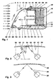
- the FIG. 1 shows a longitudinal section of a headlight (.10), for example, is part of a headlight system of a motor vehicle.
- the headlamp (10) comprises a headlamp housing (20) which in the light emission direction (5) by means of a, the vehicle contour delimiting lens (30) - in the embodiment, the lens (30), the headlight glass (30) - is closed.
- the headlight housing (20) is for example made of plastic, made of a composite material, etc. and formed, for example pot-shaped.
- headlight housing (20) has a mounting flange (21) on which the headlight glass (30), this consists eg of glass, plastic, etc., is attached.
- an insert plate (23) In the bottom (22) of the headlight housing (20) sits in this embodiment, an insert plate (23). This may include a condensate with a drain port not shown here.
- compensation openings (11) may be provided for air exchange, the total cross-section, for example, smaller than 100 square millimeters. The headlight (10) is thus at least largely closed.
- the single headlight (10) may comprise a plurality of headlight housings (20). Also, the headlight housing (20) may be divided into several sections. The headlight housing (20) may e.g. Having arranged on its outer side cooling elements for delivering the heat generated in the headlight (10) in the environment (1).
- the headlamp (10) In the interior (15) of the headlamp (10) are e.g. three light emitting diodes (40), e.g. Light-emitting diodes as light sources (40) arranged one above the other in each case in a module (90).
- the modules (90) serve for the mutual positioning of the light sources (40) and of e.g. one of the respective light source (40) optically downstream lens (43).
- a lens system can also be arranged here.
- the light-emitting chip (41) which is heated during operation of the light-emitting diode (40) is at least thermally conductively connected to a heat sink (50).
- the light-emitting chip (41) sits, for example, on a circuit board (42) to which it is electrically and thermally conductive, for example by means of a thermal paste, connected.
- At the light emitting diodes (40) facing away from the board (42) of the heat sink (50) is arranged. This includes, for example, parallel to each other vertically arranged Cooling channels (51) with eg square or rectangular cross section. It is produced, for example, as a cast component or as an extruded profile.
- a guide channel (12) is connected on the underside of the heat sink (50). This is e.g. bounded on three sides by means of a U-shaped profile (13) resting on the bottom (22). The bottom (22) bounds the underside of the guide channel (12).
- the U-shaped profile (13) may be made of metal, plastic, a composite material, etc ..
- a conveying device (70) e.g. an axial fan (71) is arranged. The latter can be attached to the heat sink (50) or to the headlight housing (20).
- a sensor system (80) is arranged in the region of the interior space (15) adjoining the headlight glass (30).
- the transmitter (81) is, for example, a light-emitting diode (81), for example enclosing with a normal to the inside (32) of the headlight glass (30) an angle of, for example 45 degrees.
- the receiver (82), eg a photodetector (82), is mirror-symmetrical to the transmitter (81). arranged, wherein the axis of symmetry is said normal.
- the angle subtended by the transmitter (81) and the receiver (82) with the normal may be greater than said angle.
- the area of the headlight glass (30) in which the normal impinges be mirrored.
- the transmitter (81) and the receiver (82) are arranged below a shading cap (83).
- This has an opening adjacent to the headlight glass (84).
- the dimming cap (83) By means of this dimming cap (83), the direct light entry from the light sources (40) to the receiver (82) can be reduced.
- the lower portion of the headlight glass (30) may be e.g. be darkly tinted.
- the sensor system (80) may comprise a condensation sensor attached, for example, to the inside (32) of the headlight glass (30), e.g. outputs a signal from an adjustable value of the relative humidity at the headlight glass.
- the signal output by the sensor system (80) may also be proportional to the relative humidity.
- the interior (15) of the headlamp (10) is e.g. heated to an operating temperature.
- the air in the interior (15) whose absolute humidity is e.g. initially lower than the absolute saturation air humidity at the operating temperature and the air pressure in the interior, absorbs moisture.
- the air pressure in the interior (15) corresponds for example to the air pressure of the environment (1).
- the relative humidity of the air in the interior (15) increases during cooling. If, during cooling, the relative humidity exceeds the absolute saturation air humidity as a function of the actual temperature - the relative humidity is then 100% - moisture condenses from the air first to the coldest section of the interior (15) of the headlamp (10), eg on the inside (32 ) of the headlight glass (30). The condensate, for example, penetrates through the opening (84) into the reflection region of the sensor system (80).
- the light-emitting diodes (40) first heat up.
- the heat generated by the light-emitting diodes (40) is conducted to the heat sinks (50) and emitted from the heat sinks (50) to the air in the interior (15) of the headlamp (10).
- the heat sinks (50) act as heat sources (50).
- the air temperature in the region of the heat sink (50) increases. With increasing temperature and, for example, constant air pressure, the ability of the air to absorb moisture increases.
- the fan (70) circulates the air in the interior (15) in the representation of FIG. 1 in the air conveying direction (75) counterclockwise to.
- the air flows through the heat sink (50), for example through the cooling channels (51) - the air is heated and passed above the modules (90) through the air duct (14) through the headlight glass (30).
- the air absorbs heat through this forced convection.
- the heated air can carry moisture from the environment, which enters eg through pressure equalization openings of the headlight (10) in this.
- the conveyor (70) thus promotes heat energy from the heat source (50) to the headlamp lens (30).
- By mixing the air inside the headlight (10) passes the absorbed moisture to the still cold headlight glass (30) and can condense there.
- the air flow (4) caused by the airstream (3) along the outside (31) of the headlight glass, which is directed counter to the air conveying direction (75), can increase the accumulation of condensate.
- Condensation of the moisture on the headlight glass (30) can also take place when the vehicle enters a cool parking garage, a tunnel, etc.
- the sensor system (80) When the ignition or the headlight (10) is switched on, the sensor system (80) is also switched on.
- the light-emitting diode (81) emits light (85) in the direction of the headlight glass (30). This light (85) is reflected both on the condensed water drops (86) and on the headlight glass (30).
- the receiver (82) receives a diffused, e.g. faint signal.
- the sensor system (80) thus communicates with the inside (32) of the headlight glass (30).
- the receiver (82) is connected to the control of the fan (70). If, for example, the light signal received by the receiver (82) falls below an adjustable lower threshold value of the level, for example, the output signal of the sensor system (80) causes the fan (70) to be switched on or to increase its speed.
- the volume flow conveyed by means of the fan (70) is amplified.
- the conveyed air flows - for example, with heat absorption on the heat sink (50) - on the headlight glass (30).
- the air flow strikes at least approximately in the entire width of the headlamp (10) on the headlight glass (30) in the upper region.
- the condensed on the headlight glass (30) moisture is displaced and / or carried by the air flow. For example, the higher the volume flow and / or the pressure and / or the temperature of the conveyed air, the higher is the deaeration.
- the control of the fan (70) may include a timer. If, for example, after a e.g. 15 seconds, the signal level received by the receiver (82) is still below the lower threshold, the controller may set the speed of the fan (70) e.g. to increase one more level. A dew on the inside (32) of the headlight glass (30) can thus be removed quickly.
- the upper threshold may be equal to the lower threshold.
- the output signal of the sensor system (80) causes the speed of the fan (70) to be maintained or lowered. If the speed is maintained, this is, for example, the speed required for further operation, which now depends on the maximum permissible operating temperature of the light-emitting diodes (40). This minimum cooling power is required so that the continuous operating temperature of the LEDs (40), for example, does not exceed 85 degrees Celsius. If the speed of the fan (70) is lowered, the amount of energy absorbed per unit time is also reduced.
- the conveying device (70) can be controlled by means of the sensor system (80) and regulated by means of the maximum permissible continuous operating temperature or vice versa. Also, a control and / or control by both parameters is conceivable.
- the insert plate (23) is designed as a condensation plate
- the air flows in the guide channel (12) along this condensation plate.
- the edge region of the air flow is cooled.
- the relative humidity - at least in the edge area of the air flow - exceeds the saturation limit, which depends on the temperature and the pressure.
- Moisture condenses on the condensation plate from the air flow.
- the condensation takes place for example as a film condensation.
- the absolute and the relative humidity of the headlight (10) promoted air is thereby reduced.
- the condensation can also take place as dropwise condensation.
- the resulting condensate is then passed, for example through a drain opening into the environment (1).
- a separate heat source can be arranged in the headlight (10).
- the fan (70) can heat the circulated air.
- a centrifugal fan can be used.
- a reversal of the conveying direction (75) is conceivable.
- the fan (70) can be above or be arranged below the heat sink (50). It is also conceivable to arrange a separate fan (70) only for removing the condensate.
- the heat dissipation of the light sources (40) can then take place, for example, by means of a further conveying device, which can be arranged inside or outside the spotlight housing (20). Also, a with the light sources (40) thermally connected heat sink outside the headlight housing (20) may be arranged.
- the heat generated by the light sources (40) can also be obtained by means of water cooling, e.g. be derived by means of a heat exchanger.
- a headlamp (10) constructed in this way then has, for example, a separate ventilator (70) which is actuated by means of a sensor system (80) as a function of the condensate infiltration of the headlight glass (30).
- a separate ventilator (70) which is actuated by means of a sensor system (80) as a function of the condensate infiltration of the headlight glass (30).
- an additional heat source in this headlight (10) by means of the sensor system (80) can be controlled.
- a headlight (10) with an axial fan (71) is shown, for example, is inclined at 45 degrees.
- the diameter of the axial fan (71) is for example 40% larger than the diameter of the in FIG. 1 illustrated fan (10).
- a conveyor device (70) can be used, which - compared to the embodiment according to FIG. 1 - Promotes a higher flow rate at the same speed.
- the functions of the sensor system (80) and the conveyor device (70) correspond to the functions of these devices, as in connection with the embodiment of the FIG. 1 are described.
- FIG. 5 shows a headlight (10) with eg six modules (90) and two heat sinks (50, 52). Three modules each (90) are arranged on one of the two, for example, at right angles to each other arranged heat sink (50, 52). Between the two heat sinks (50, 52) is arranged as a conveying device (70), a centrifugal fan (72). The air delivered by the centrifugal fan (72) can therefore already be preheated by means of the first heat source (50).
- the second heat sink (52) is e.g. constructed in two parts from a lower (53) and an upper heat sink part (54). These two heat sink parts (53, 54) surround, for example, eight air ducts (56). In an arrangement of the second heat sink (52) on the roof (24) of the headlight housing (20) may optionally be dispensed with the upper heat sink portion (54).
- All modules (90) can also be mounted on a common, e.g. curved board (42) can be arranged.
- the heat sinks (50, 52) can be interconnected e.g. be connected by means of a bypass, which bypasses the fan (70).
- the lower heat sink portion (53) of the second heat sink (52) is shown.
- the cross section of the individual air ducts (56) widens continuously from the inlet side (57) to the outlet side (58).
- the side surfaces of the individual ribs (59) are, for example, parabolic surface sections.
- the FIG. 7 shows a headlamp (1), which is similar to that in the FIG. 1 illustrated headlights.
- the insert plate (23) embodied here as a heat sink (60) is a condensation plate (61) with an electrical cooling element (65), eg a Peltier element.
- an electrical cooling element (65) eg a Peltier element.
- the inner surface (62) of the condensation plate (61) for example, by a temperature difference of 10 K cooler set as the temperature of the interior (15).
- the minimum temperature of the heat sink (60) is the temperature of the triple point of water at which all three phase states coexist. At temperatures below the triple point no condensation occurs. If the ambient temperature (1) is below this specific temperature, the risk of condensation on the headlight glass (30) does not increase - even if the outside temperatures continue to fall.
- the condensation takes place, as in connection with the embodiment of FIG. 1 described.
- the absolute amount of moisture of the air conveyed in the headlamp can be reduced, whereby also the relative humidity in the atmosphere of the interior (15) is reduced.
- a labyrinth 64
- a gas-permeable membrane etc.
- the Peltier element (65) can be switched off electrically as soon as the relative humidity in the interior (15) is below a threshold value. When approaching this threshold or when exceeding this threshold, the Peltier element (65) can be turned on again to reduce the amount of moisture in the headlight (10).
- the sensor system (80) and the conveyor (70) function as described in connection with FIG FIG. 1 described.
- a commercially available moisture sensor can also be used.
- the conveyor device (70) can suck in air from the environment (1) of the headlamp (10).
- the intake is connected to the engine pre-heating of the motor vehicle.
- filtered air enters the interior (15) of the headlamp (10).
- the air can be discharged into the environment (1) again after flowing along the lens (30).
- the headlamp system may include a sensor system disposed outside the headlamp (10).
- This sensor system can be arranged, for example, on the bumper of the motor vehicle.
- a characteristic value is determined, for example, from the temperature, the atmospheric pressure, the absolute or relative atmospheric humidity in the environment (1) and optionally a correction factor.
- the correction factor - it may be nonlinear or linear to change the measured parameters - takes into account e.g. a difference of the humidity of the interior (15) to the humidity of the environment (1).
- the output signal of the sensor system is then e.g. depending on the thus determined characteristic value of the relative humidity in the interior of the headlamp (10).
- the sensor system controls and / or regulates the conveying device.
- Such a headlamp system may comprise a plurality of headlights (10) whose conveying devices are controlled and / or regulated by means of a common sensor system.
- shielding plates can additionally be arranged against the heat radiation of the motor. These shielding plates may also be parts of the body and / or a front module.
Landscapes
- Engineering & Computer Science (AREA)
- General Engineering & Computer Science (AREA)
- Non-Portable Lighting Devices Or Systems Thereof (AREA)
- Arrangement Of Elements, Cooling, Sealing, Or The Like Of Lighting Devices (AREA)
- Lighting Device Outwards From Vehicle And Optical Signal (AREA)
Applications Claiming Priority (1)
| Application Number | Priority Date | Filing Date | Title |
|---|---|---|---|
| DE102007036486A DE102007036486A1 (de) | 2007-08-01 | 2007-08-01 | Scheinwerfersystem mit gesteuerter und/oder geregelter Fördervorrichtung |
Publications (3)
| Publication Number | Publication Date |
|---|---|
| EP2020569A2 true EP2020569A2 (fr) | 2009-02-04 |
| EP2020569A3 EP2020569A3 (fr) | 2010-03-10 |
| EP2020569B1 EP2020569B1 (fr) | 2011-10-19 |
Family
ID=39797436
Family Applications (1)
| Application Number | Title | Priority Date | Filing Date |
|---|---|---|---|
| EP08013734A Not-in-force EP2020569B1 (fr) | 2007-08-01 | 2008-07-31 | Système de phare doté d'un dispositif de désembuage commandé et/ou réglé |
Country Status (3)
| Country | Link |
|---|---|
| EP (1) | EP2020569B1 (fr) |
| DE (1) | DE102007036486A1 (fr) |
| SI (1) | SI2020569T1 (fr) |
Cited By (19)
| Publication number | Priority date | Publication date | Assignee | Title |
|---|---|---|---|---|
| JP2010108637A (ja) * | 2008-10-28 | 2010-05-13 | Harison Toshiba Lighting Corp | 車両用前照灯 |
| DE102009055681A1 (de) * | 2009-11-25 | 2011-05-26 | Bayerische Motoren Werke Aktiengesellschaft | Kraftfahrzeugleuchte |
| EP2306084A3 (fr) * | 2009-09-30 | 2011-07-06 | Valeo Vision | Dispositif d'éclairage et/ou de signalisation pour véhicule automobile |
| EP2375136A1 (fr) * | 2010-04-09 | 2011-10-12 | Odelo GmbH | Lampe de véhicule automobile |
| US8967842B2 (en) | 2013-06-26 | 2015-03-03 | Toyota Motor Engineering & Manufacturing North America, Inc. | Lamp condensation reduction system |
| EP2404110B1 (fr) * | 2009-03-05 | 2016-08-17 | OSRAM GmbH | Dispositif d'eclairage avec au mois une dissipateur thermique |
| EP3159596A1 (fr) * | 2015-08-04 | 2017-04-26 | LG Innotek Co., Ltd. | Lampe véhiculaire |
| FR3043171A1 (fr) * | 2015-11-04 | 2017-05-05 | Peugeot Citroen Automobiles Sa | Dispositif d’eclairage a diode pour vehicule automobile |
| FR3051889A1 (fr) * | 2016-05-31 | 2017-12-01 | Valeo Vision | Dispositif d'eclairage et/ou de signalisation pour vehicule automobile equipe d'un module lumineux refroidi au moyen d'un generateur d'un flux d'air |
| US9982857B2 (en) | 2015-10-20 | 2018-05-29 | Toyota Motor Engineering & Manufacturing North America, Inc. | Vehicle lights including moisture management apparatuses |
| EP3327335A1 (fr) * | 2016-11-28 | 2018-05-30 | Automotive Lighting Reutlingen GmbH | Phare et procédé de fonctionnement d'un phare |
| CN108397742A (zh) * | 2018-04-13 | 2018-08-14 | 华域视觉科技(上海)有限公司 | 防起雾车灯及汽车 |
| US10337690B2 (en) | 2016-11-22 | 2019-07-02 | Osram Sylvania Inc. | Automotive LED module with heat sink and fan |
| CN111795353A (zh) * | 2020-07-22 | 2020-10-20 | 上汽大众汽车有限公司 | 一种自动除雾的汽车智能前大灯 |
| EP3555523A4 (fr) * | 2016-12-16 | 2021-03-31 | Foshan Ichikoh Valeo Auto Lighting Systems Co., Ltd. | Ensemble de régulation d'une source de lumière, dispositif d'éclairage et/ou de signalisation, dispositif de réglage, dispositif d'éclairage et véhicule automobile, dispositif de lunette, dispositif de guidage de gaz, et dispositif d'éclairage et/ou de signalisation le contenant |
| WO2022063416A1 (fr) | 2020-09-28 | 2022-03-31 | HELLA GmbH & Co. KGaA | Lentille couvercle pour un dispositif d'éclairage de véhicule |
| CN114688498A (zh) * | 2022-03-29 | 2022-07-01 | 东风汽车集团股份有限公司 | 一种车灯除雾装置 |
| WO2023198372A1 (fr) * | 2022-04-12 | 2023-10-19 | Mercedes-Benz Group AG | Module de régulation de température et phare |
| DE102022122285A1 (de) | 2022-09-02 | 2024-03-07 | HELLA GmbH & Co. KGaA | Kunststoffabschlussscheibe für eine Beleuchtungseinrichtung eines Kraftfahrzeugs und Verfahren zur Herstellung einer Kunststoffabschlussscheibe |
Families Citing this family (6)
| Publication number | Priority date | Publication date | Assignee | Title |
|---|---|---|---|---|
| DE102009006093B4 (de) * | 2009-01-26 | 2018-06-14 | Dr. Ing. H.C. F. Porsche Aktiengesellschaft | Fahrzeugscheinwerfer |
| CN102009640B (zh) * | 2010-11-25 | 2012-05-23 | 奇瑞汽车股份有限公司 | 一种汽车大灯除雾装置及方法 |
| DE102011004746B4 (de) | 2011-02-25 | 2023-09-28 | Osram Gmbh | Halbleiter-Leuchtmodul und Fahrzeugleuchte |
| DE102012008089A1 (de) * | 2012-04-21 | 2013-10-24 | Volkswagen Aktiengesellschaft | Beleuchtungsvorrichtung für ein Kraftfahrzeug |
| DE102013001287A1 (de) * | 2013-01-25 | 2014-07-31 | GM Global Technology Operations LLC (n. d. Ges. d. Staates Delaware) | Kraftfahrzeugscheinwerfer |
| DE102017117555A1 (de) * | 2017-08-02 | 2019-02-07 | Automotive Lighting Reutlingen Gmbh | Scheinwerfer für ein Kraftfahrzeug |
Citations (1)
| Publication number | Priority date | Publication date | Assignee | Title |
|---|---|---|---|---|
| DE102005019651A1 (de) | 2005-04-26 | 2006-11-09 | Schefenacker Vision Systems Germany Gmbh | Scheinwerfer mit Trocknungsmittel |
Family Cites Families (5)
| Publication number | Priority date | Publication date | Assignee | Title |
|---|---|---|---|---|
| FR2701756B1 (fr) * | 1993-02-17 | 1995-05-19 | Peugeot | Bloc optique ventilé notamment pour véhicule automobile. |
| DE102004025624A1 (de) * | 2004-05-25 | 2005-12-15 | Hella Kgaa Hueck & Co. | Scheinwerfer mit Wärmetauscher zur Kühlung von Leuchtmitteln |
| DE102005027087A1 (de) * | 2005-06-11 | 2006-12-14 | Leopold Kostal Gmbh & Co. Kg | Beschlagsensor für ein Kraftfahrzeug |
| DE102005060736B4 (de) * | 2005-12-16 | 2008-11-20 | Odelo Gmbh | Scheinwerfer mit Kondensatabscheider |
| US8410402B2 (en) * | 2006-08-28 | 2013-04-02 | Dialight Corporation | Method and apparatus for using light emitting diodes for removing moisture |
-
2007
- 2007-08-01 DE DE102007036486A patent/DE102007036486A1/de not_active Ceased
-
2008
- 2008-07-31 EP EP08013734A patent/EP2020569B1/fr not_active Not-in-force
- 2008-07-31 SI SI200830497T patent/SI2020569T1/sl unknown
Patent Citations (1)
| Publication number | Priority date | Publication date | Assignee | Title |
|---|---|---|---|---|
| DE102005019651A1 (de) | 2005-04-26 | 2006-11-09 | Schefenacker Vision Systems Germany Gmbh | Scheinwerfer mit Trocknungsmittel |
Cited By (26)
| Publication number | Priority date | Publication date | Assignee | Title |
|---|---|---|---|---|
| JP2010108637A (ja) * | 2008-10-28 | 2010-05-13 | Harison Toshiba Lighting Corp | 車両用前照灯 |
| EP2404110B1 (fr) * | 2009-03-05 | 2016-08-17 | OSRAM GmbH | Dispositif d'eclairage avec au mois une dissipateur thermique |
| EP2306084A3 (fr) * | 2009-09-30 | 2011-07-06 | Valeo Vision | Dispositif d'éclairage et/ou de signalisation pour véhicule automobile |
| DE102009055681A1 (de) * | 2009-11-25 | 2011-05-26 | Bayerische Motoren Werke Aktiengesellschaft | Kraftfahrzeugleuchte |
| EP2375136A1 (fr) * | 2010-04-09 | 2011-10-12 | Odelo GmbH | Lampe de véhicule automobile |
| US8967842B2 (en) | 2013-06-26 | 2015-03-03 | Toyota Motor Engineering & Manufacturing North America, Inc. | Lamp condensation reduction system |
| US9829173B2 (en) | 2015-08-04 | 2017-11-28 | Lg Innotek Co., Ltd. | Vehicular lamp |
| EP3159596A1 (fr) * | 2015-08-04 | 2017-04-26 | LG Innotek Co., Ltd. | Lampe véhiculaire |
| US9982857B2 (en) | 2015-10-20 | 2018-05-29 | Toyota Motor Engineering & Manufacturing North America, Inc. | Vehicle lights including moisture management apparatuses |
| FR3043171A1 (fr) * | 2015-11-04 | 2017-05-05 | Peugeot Citroen Automobiles Sa | Dispositif d’eclairage a diode pour vehicule automobile |
| CN107448860B (zh) * | 2016-05-31 | 2022-02-01 | 法雷奥照明公司 | 设有借助气流发生器冷却的发光模块的机动车辆照明和/或信号设备 |
| EP3252369A1 (fr) * | 2016-05-31 | 2017-12-06 | Valeo Vision | Dispositif d'eclairage et/ou de signalisation pour vehicule automobile equipe d'un module lumineux refroidi au moyen d'un generateur d'un flux d'air |
| CN107448860A (zh) * | 2016-05-31 | 2017-12-08 | 法雷奥照明公司 | 设有借助气流发生器冷却的发光模块的机动车辆照明和/或信号设备 |
| US10228105B2 (en) | 2016-05-31 | 2019-03-12 | Valeo Vision | Lighting and/or signaling device for a motor vehicle, provided with a light module cooled by means of an air flow generator |
| FR3051889A1 (fr) * | 2016-05-31 | 2017-12-01 | Valeo Vision | Dispositif d'eclairage et/ou de signalisation pour vehicule automobile equipe d'un module lumineux refroidi au moyen d'un generateur d'un flux d'air |
| US10337690B2 (en) | 2016-11-22 | 2019-07-02 | Osram Sylvania Inc. | Automotive LED module with heat sink and fan |
| EP3327335A1 (fr) * | 2016-11-28 | 2018-05-30 | Automotive Lighting Reutlingen GmbH | Phare et procédé de fonctionnement d'un phare |
| EP3555523A4 (fr) * | 2016-12-16 | 2021-03-31 | Foshan Ichikoh Valeo Auto Lighting Systems Co., Ltd. | Ensemble de régulation d'une source de lumière, dispositif d'éclairage et/ou de signalisation, dispositif de réglage, dispositif d'éclairage et véhicule automobile, dispositif de lunette, dispositif de guidage de gaz, et dispositif d'éclairage et/ou de signalisation le contenant |
| CN108397742A (zh) * | 2018-04-13 | 2018-08-14 | 华域视觉科技(上海)有限公司 | 防起雾车灯及汽车 |
| CN111795353A (zh) * | 2020-07-22 | 2020-10-20 | 上汽大众汽车有限公司 | 一种自动除雾的汽车智能前大灯 |
| WO2022063416A1 (fr) | 2020-09-28 | 2022-03-31 | HELLA GmbH & Co. KGaA | Lentille couvercle pour un dispositif d'éclairage de véhicule |
| US12292175B2 (en) | 2020-09-28 | 2025-05-06 | HELLA GmbH & Co. KGaA | Cover lens for a vehicle lighting device |
| CN114688498A (zh) * | 2022-03-29 | 2022-07-01 | 东风汽车集团股份有限公司 | 一种车灯除雾装置 |
| WO2023198372A1 (fr) * | 2022-04-12 | 2023-10-19 | Mercedes-Benz Group AG | Module de régulation de température et phare |
| US12504146B2 (en) | 2022-04-12 | 2025-12-23 | Mercedes-Benz Group AG | Temperature control module and headlight |
| DE102022122285A1 (de) | 2022-09-02 | 2024-03-07 | HELLA GmbH & Co. KGaA | Kunststoffabschlussscheibe für eine Beleuchtungseinrichtung eines Kraftfahrzeugs und Verfahren zur Herstellung einer Kunststoffabschlussscheibe |
Also Published As
| Publication number | Publication date |
|---|---|
| EP2020569B1 (fr) | 2011-10-19 |
| EP2020569A3 (fr) | 2010-03-10 |
| DE102007036486A1 (de) | 2009-02-05 |
| SI2020569T1 (sl) | 2012-03-30 |
Similar Documents
| Publication | Publication Date | Title |
|---|---|---|
| EP2020569B1 (fr) | Système de phare doté d'un dispositif de désembuage commandé et/ou réglé | |
| DE102011084114B4 (de) | Kraftfahrzeugscheinwerfer | |
| EP1818609A2 (fr) | Dispositif de séchage pour appareils d'éclairage ou électronique | |
| EP2229555B1 (fr) | Dispositif de refroidissement de sources lumineuses à semi-conducteur et projecteur doté de ce dispositif | |
| DE102005019651B4 (de) | Scheinwerfer mit Trocknungsmittel | |
| EP0859188A2 (fr) | Dispositif pour éviter la formation de la rosée pour projecteur | |
| DE102005060736B4 (de) | Scheinwerfer mit Kondensatabscheider | |
| DE10346270B4 (de) | Fahrzeugscheinwerfer mit Heizung | |
| DE112013006307T5 (de) | Entfeuchtungseinrichtung | |
| DE102007057056A1 (de) | Scheinwerfer für ein Kraftfahrzeug mit Mitteln zum Wärmeaustausch zwischen dem Innenraum und der Außenseite des Scheinwerfers | |
| DE10213680A1 (de) | Scheinwerfer für Fahrzeuge | |
| DE19733000A1 (de) | Scheinwerferbetauungsschutz | |
| DE10255443B4 (de) | Fahrzeugscheinwerfer | |
| DE102017204641A1 (de) | Vorrichtung zur Messung von Umgebungsbedingungen unter gezielter Ausnutzung des Kamineffekts zur Belüftung der Vorrichtung | |
| WO2006034755A1 (fr) | Projecteurs de vehicules | |
| DE10331835A1 (de) | Leuchte für ein Fahrzeug mit einer Betauungsschutzvorrichtung | |
| EP4022216B1 (fr) | Projecteur de véhicule automobile et circuit de refroidissement d'un véhicule automobile | |
| EP2375136A1 (fr) | Lampe de véhicule automobile | |
| DE10319363A1 (de) | Leuchtvorrichtung für Fahrzeuge und Verfahren zum Steuern und/oder Regeln einer Betauungsschutzvorrichtung einer Leuchtvorrichtung für Fahrzeuge | |
| DE102020007598A1 (de) | Scheinwerfer mit einer beheizbaren Abdeckscheibe und Verfahren zum Betreiben des Scheinwerfers | |
| DE102009048662A1 (de) | Gekühltes Beleuchtungssystem mit oberflächenmontierter Lichtquelle | |
| EP3822536A1 (fr) | Phares pourvu de dispositif de protection contre la condensation | |
| DE102016217149B4 (de) | Verfahren zum Betreiben einer Beleuchtungsvorrichtung, Beleuchtungsvorrichtung für ein Kraftfahrzeug und Kraftfahrzeug | |
| DE102019123065A1 (de) | Verbund aus einem Wärmetauscher aufweisenden Scheinwerfer und einem Kühlkreislauf eines Kraftfahrzeugs | |
| DE10340073A1 (de) | Fahrzeugleuchte |
Legal Events
| Date | Code | Title | Description |
|---|---|---|---|
| PUAI | Public reference made under article 153(3) epc to a published international application that has entered the european phase |
Free format text: ORIGINAL CODE: 0009012 |
|
| AK | Designated contracting states |
Kind code of ref document: A2 Designated state(s): AT BE BG CH CY CZ DE DK EE ES FI FR GB GR HR HU IE IS IT LI LT LU LV MC MT NL NO PL PT RO SE SI SK TR |
|
| AX | Request for extension of the european patent |
Extension state: AL BA MK RS |
|
| PUAL | Search report despatched |
Free format text: ORIGINAL CODE: 0009013 |
|
| AK | Designated contracting states |
Kind code of ref document: A3 Designated state(s): AT BE BG CH CY CZ DE DK EE ES FI FR GB GR HR HU IE IS IT LI LT LU LV MC MT NL NO PL PT RO SE SI SK TR |
|
| AX | Request for extension of the european patent |
Extension state: AL BA MK RS |
|
| 17P | Request for examination filed |
Effective date: 20100909 |
|
| AKX | Designation fees paid |
Designated state(s): DE FR IT SI |
|
| GRAP | Despatch of communication of intention to grant a patent |
Free format text: ORIGINAL CODE: EPIDOSNIGR1 |
|
| RIC1 | Information provided on ipc code assigned before grant |
Ipc: F21Y 101/02 20060101ALN20110405BHEP Ipc: F21W 101/10 20060101ALN20110405BHEP Ipc: F21S 8/10 20060101ALI20110405BHEP Ipc: F21V 31/03 20060101AFI20110405BHEP |
|
| GRAS | Grant fee paid |
Free format text: ORIGINAL CODE: EPIDOSNIGR3 |
|
| GRAA | (expected) grant |
Free format text: ORIGINAL CODE: 0009210 |
|
| AK | Designated contracting states |
Kind code of ref document: B1 Designated state(s): DE FR IT SI |
|
| REG | Reference to a national code |
Ref country code: DE Ref legal event code: R096 Ref document number: 502008005217 Country of ref document: DE Effective date: 20111215 |
|
| PLBE | No opposition filed within time limit |
Free format text: ORIGINAL CODE: 0009261 |
|
| STAA | Information on the status of an ep patent application or granted ep patent |
Free format text: STATUS: NO OPPOSITION FILED WITHIN TIME LIMIT |
|
| 26N | No opposition filed |
Effective date: 20120720 |
|
| REG | Reference to a national code |
Ref country code: DE Ref legal event code: R097 Ref document number: 502008005217 Country of ref document: DE Effective date: 20120720 |
|
| PGFP | Annual fee paid to national office [announced via postgrant information from national office to epo] |
Ref country code: SI Payment date: 20130620 Year of fee payment: 6 |
|
| REG | Reference to a national code |
Ref country code: DE Ref legal event code: R082 Ref document number: 502008005217 Country of ref document: DE Representative=s name: KAUFMANN, URSULA, DIPL.-PHYS. DR.RER.NAT., DE Ref country code: DE Ref legal event code: R082 Ref document number: 502008005217 Country of ref document: DE Representative=s name: RPK PATENTANWAELTE REINHARDT, POHLMANN UND KAU, DE |
|
| REG | Reference to a national code |
Ref country code: DE Ref legal event code: R082 Ref document number: 502008005217 Country of ref document: DE Representative=s name: RPK PATENTANWAELTE REINHARDT, POHLMANN UND KAU, DE |
|
| REG | Reference to a national code |
Ref country code: SI Ref legal event code: KO00 Effective date: 20150318 |
|
| PG25 | Lapsed in a contracting state [announced via postgrant information from national office to epo] |
Ref country code: SI Free format text: LAPSE BECAUSE OF NON-PAYMENT OF DUE FEES Effective date: 20140801 |
|
| REG | Reference to a national code |
Ref country code: FR Ref legal event code: PLFP Year of fee payment: 9 |
|
| REG | Reference to a national code |
Ref country code: FR Ref legal event code: PLFP Year of fee payment: 10 |
|
| REG | Reference to a national code |
Ref country code: FR Ref legal event code: PLFP Year of fee payment: 11 |
|
| PGFP | Annual fee paid to national office [announced via postgrant information from national office to epo] |
Ref country code: IT Payment date: 20190730 Year of fee payment: 12 Ref country code: FR Payment date: 20190719 Year of fee payment: 12 Ref country code: DE Payment date: 20190719 Year of fee payment: 12 |
|
| REG | Reference to a national code |
Ref country code: DE Ref legal event code: R119 Ref document number: 502008005217 Country of ref document: DE |
|
| PG25 | Lapsed in a contracting state [announced via postgrant information from national office to epo] |
Ref country code: FR Free format text: LAPSE BECAUSE OF NON-PAYMENT OF DUE FEES Effective date: 20200731 |
|
| PG25 | Lapsed in a contracting state [announced via postgrant information from national office to epo] |
Ref country code: DE Free format text: LAPSE BECAUSE OF NON-PAYMENT OF DUE FEES Effective date: 20210202 |
|
| PG25 | Lapsed in a contracting state [announced via postgrant information from national office to epo] |
Ref country code: IT Free format text: LAPSE BECAUSE OF NON-PAYMENT OF DUE FEES Effective date: 20200731 |