EP2020576A2 - Collecteur solaire destiné au réchauffement d'un liquide - Google Patents
Collecteur solaire destiné au réchauffement d'un liquide Download PDFInfo
- Publication number
- EP2020576A2 EP2020576A2 EP20080161712 EP08161712A EP2020576A2 EP 2020576 A2 EP2020576 A2 EP 2020576A2 EP 20080161712 EP20080161712 EP 20080161712 EP 08161712 A EP08161712 A EP 08161712A EP 2020576 A2 EP2020576 A2 EP 2020576A2
- Authority
- EP
- European Patent Office
- Prior art keywords
- solar collector
- manifold
- collector according
- tubes
- wall
- Prior art date
- Legal status (The legal status is an assumption and is not a legal conclusion. Google has not performed a legal analysis and makes no representation as to the accuracy of the status listed.)
- Withdrawn
Links
Images

Classifications
-
- F—MECHANICAL ENGINEERING; LIGHTING; HEATING; WEAPONS; BLASTING
- F24—HEATING; RANGES; VENTILATING
- F24S—SOLAR HEAT COLLECTORS; SOLAR HEAT SYSTEMS
- F24S10/00—Solar heat collectors using working fluids
- F24S10/70—Solar heat collectors using working fluids the working fluids being conveyed through tubular absorbing conduits
- F24S10/73—Solar heat collectors using working fluids the working fluids being conveyed through tubular absorbing conduits the tubular conduits being of plastic material
-
- F—MECHANICAL ENGINEERING; LIGHTING; HEATING; WEAPONS; BLASTING
- F24—HEATING; RANGES; VENTILATING
- F24S—SOLAR HEAT COLLECTORS; SOLAR HEAT SYSTEMS
- F24S80/00—Details, accessories or component parts of solar heat collectors not provided for in groups F24S10/00-F24S70/00
- F24S80/30—Arrangements for connecting the fluid circuits of solar collectors with each other or with other components, e.g. pipe connections; Fluid distributing means, e.g. headers
-
- F—MECHANICAL ENGINEERING; LIGHTING; HEATING; WEAPONS; BLASTING
- F28—HEAT EXCHANGE IN GENERAL
- F28F—DETAILS OF HEAT-EXCHANGE AND HEAT-TRANSFER APPARATUS, OF GENERAL APPLICATION
- F28F1/00—Tubular elements; Assemblies of tubular elements
- F28F1/08—Tubular elements crimped or corrugated in longitudinal section
-
- Y—GENERAL TAGGING OF NEW TECHNOLOGICAL DEVELOPMENTS; GENERAL TAGGING OF CROSS-SECTIONAL TECHNOLOGIES SPANNING OVER SEVERAL SECTIONS OF THE IPC; TECHNICAL SUBJECTS COVERED BY FORMER USPC CROSS-REFERENCE ART COLLECTIONS [XRACs] AND DIGESTS
- Y02—TECHNOLOGIES OR APPLICATIONS FOR MITIGATION OR ADAPTATION AGAINST CLIMATE CHANGE
- Y02E—REDUCTION OF GREENHOUSE GAS [GHG] EMISSIONS, RELATED TO ENERGY GENERATION, TRANSMISSION OR DISTRIBUTION
- Y02E10/00—Energy generation through renewable energy sources
- Y02E10/40—Solar thermal energy, e.g. solar towers
- Y02E10/44—Heat exchange systems
Definitions
- the present invention relates to a solar collector for heating a liquid, comprising at least two distribution pipes made of plastic for supply and discharge of the liquid to be heated, each having a manifold wall, distributed over the length of a plurality of pipe connection piece made of plastic for the connection of collector pipes are, which connect the distribution pipes together.
- Such solar collectors are used in various embodiments for heating the water of swimming pools, permanently installed or freely deployable swimming pools, children's pools in the indoor or outdoor area, garden showers and the like.
- the solar collector is continuously flowed through by the water to be heated, the water flow absorbs heat from the solar collector and is continuously removed from it as heated water.
- the resulting temperature depends on the collector surface and amount of flowing water from the sunlight and is usually well below 50 ° C.
- a solar collector of this kind is in the DE 10 2005 061 008 B3 described.
- the solar collector has a mat-shaped arrangement formed of numerous collector tubes extending parallel to one another, through which the water to be heated flows.
- the collector pipes end on both sides in common distribution pipes.
- the water to be heated is supplied to the collector, distributed in the collector tubes and from it derived again.
- Distribution pipes therefore have a significantly larger internal diameter than collector pipes.
- the distribution pipes contribute because of their property as a lateral boundary of the mat-shaped collector arrangement for shape stabilization of the same and generally have a certain flexural rigidity. This also facilitates the production of watertight connections to the liquid supply and discharge, but makes it difficult to transport the tubes. Therefore, the distribution pipes are usually composed of shorter individual pieces, for example by gluing. All pipes of the known solar collector are made of plastic. It has also been shown that the frost resistance of the known solar collectors is insufficient.
- Another type of solar absorber which is not the subject of the invention, is used for heat generation or recovery in the field of domestic water heating and domestic heating.
- high temperatures are usually desired above 60 ° C, which is achieved by a discontinuous operation of the absorber by water or another heat transfer medium remains within the absorber and is heated therein until it has reached the target temperature.
- a solar absorber is from the DE 100 39 111 B4 known. It consists of metal and is composed of so-called strip absorbers, which consist of capillary tubes made of copper, which are connected to a collection tube made of stainless steel by soldering. In order to improve the frost resistance of the solar collector is proposed to form the manifold with corrugated pipe profile.
- Soldering the capillary tubes during the soldering process involves the risk that the wall of the collecting tube, which is designed as a corrugated tube and therefore thin, is impaired or even damaged.
- the thermal loading and the mechanical action of the additional solder material can adversely affect the course of force lines and lead to increased mechanical stresses in the region of the solder joint.
- the manifold is subject to pressure and temperature fluctuations when intended Use constantly deformations, which are still favored by the corrugated tube profile of the manifold. Prolonged deformation leads to fatigue of the material and eventually to breakage or cracking in the area of the solder joints.
- the tightness of the solder joint is to be checked later and its installation is relatively complex.
- the present invention has for its object to optimize solar collectors made of plastic in terms of ease of installation, frost resistance and fatigue strength.
- the previously used, rigid distribution pipes have a smooth outer wall.
- liquid-tight connections for the supply and discharge of the liquid to be heated can be attached relatively easily to the ends of the distributor tube, the smooth cylinder jacket surface serving as a sealing surface. This also withstands a radially inwardly directed contact pressure readily.
- the solar collector according to the invention differs therefrom in that at least one of the distributor pipes, preferably several, particularly preferably all distributor pipes of the solar collector, have a corrugated profile, as is also known from corrugated pipe.
- the manifold with corrugated tube profile is characterized by a certain flexibility and by a high structural rigidity against external pressure at relatively low wall thickness.
- the manifold with corrugated tube profile can be available in pieces of predetermined length or the manifold can be wound, for example, in roll form, which simplifies storage and facilitates transport to the job site.
- a mat-like, planar solar collector constructed using flexible distributor pipes also shows a certain flexibility in the direction of the mat normal.
- the areal arrangement of the collector tubes can therefore easily adapt to unevenness of the base.
- curved surfaces may be mentioned on which (wall) or around (pillars, towers) of the solar collector can rest over the entire surface, which is not only advantageous from an aesthetic point of view, but also prevents damage to only locally resting parts of the solar collector by acting bending forces.
- the collector pipes are attached, for example, to the pipe connection piece. It is important that manifold and pipe connection form an integral composite, that is, they are made in one piece.
- the pipe connection pieces are integrally connected to the outer wall of the manifold and are advantageously formed in the same operation. Examples include a continuous extrusion blow molding or a batch blow molding process.
- the integral composite has the advantage that the cost of the subsequent formation of a positive and tight connection between the manifold and pipe connection (such as by welding plastic parts) is eliminated as well as the usually associated with thermal stress of the manifold. A disturbance of the given during the production of the manifold pipe lines of force (with rather low mechanical stresses) by a subsequent attachment of parts is avoided, and thus the formation of voltage spikes.
- the integrally molded pipe socket therefore contributes to a lower susceptibility to cracking even with permanent deformation forces.
- the pipe connection pieces designed in this way show a certain flexibility, which in turn has an advantageous effect on the frost resistance of the solar collector.
- the corrugated profile of the pipe connection piece ensures on the one hand a high buckling and shape rigidity with comparatively small wall thickness, and the corrugated or ribbed surface of the socket secures the pushed-on collector pipe against slipping.
- the pipe connection pieces are arranged along a first longitudinal side of the distributor tube wall, and on the first longitudinal side opposite the second longitudinal side of the distributor tube wall, a plurality of embossing elements for shape stabilization are provided.
- the embossing elements are machine-made formations in the area of the distributor tube wall, each of which approximates a pipe connecting piece approximately, ideally exactly.
- the embossing elements are formed as annular depressions or elevations with the radial dimensions of the pipe connection piece.
- the embossing elements cause a compensation of mechanical stresses that would be generated as a result of the only one-sided integrated in the manifold pipe connection pipe, and they thus contribute to a better dimensional stability and density of the solar collector. In addition, they increase the rigidity of the corrugated pipe.
- each pipe connection piece on the first longitudinal side in each case a stamping element on the second longitudinal side of the manifold wall exactly opposite. Deviations from this ideal case usually lead to higher mechanical stresses within the manifold.
- embossing elements are an integral part of the manifold with corrugated profile.
- the embossing elements and the pipe connection piece are in this case integrally connected to the outer wall of the manifold and are formed in the same operation.
- the integral composite has the advantage that the expense of a subsequent generation of embossing elements and the associated disturbances of the line of force in the wall of the manifold can be avoided.
- the manifold is formed in one piece.
- the one-piece design of the at least one distributor tube is facilitated by its corrugated profile. Because of the flexibility of the "corrugated tube” this can be made available in wound form, as is already common for the collector tubes. A portion of the specified by the specific circumstances length of the manifold is quasi “cut off the role". A distributor tube on a roll can therefore be available "on site” in a greater length than was customary in the case of manifolds that have been previously pieced. Thus, the length of the flexible manifold can be adapted directly to the specific circumstances and eliminate the previously necessary work for liquid-tight bonding of sections of the manifold. The installation effort is lower.
- collector tubes are designed as corrugated tubes which have uniformly distributed marking regions with reduced outside diameter over their length.
- Collector pipes are often made in the form of corrugated pipes, and they are cut off during assembly of the solar collector as needed from the roll.
- the marking areas are distributed at a constant distance from each other - for example, every 50 cm - over the length of the collector tube, and they are visually recognizable by a reduced outer diameter.
- markings of another type may be provided, such as markings by color or embossing of the surface.
- One function of the marking areas is to facilitate measuring the pipe length when trimming.
- each stabilization profile over its length on several open, semicircular receptacles for the collector tubes.
- the size of the images is designed for the reduced outer diameter of the marking areas.
- the collector tubes are fixed in one or more stabilization profiles by means of their marking areas. A shift in the longitudinal axis direction is then possible only in the scope of the length of the marking area.
- the marking areas are formed as wall areas with finer waveform and thicker wall thickness.
- the collector tube shows a finer waveform in its marker areas - also referred to as “fine wave” or “fine wave” hereinafter - and otherwise a coarser waveform, which is also referred to below as “coarse wave” or “coarse wave”.
- the fine-wave areas are visually easily recognizable and they are characterized by a comparatively larger wall thickness and thus by a higher mechanical stability. This reduces the risk of mechanical damage if a fixation acts on these areas, such as by clipping into recordings of a stabilization profile, as described above.
- the manifold is associated with a rigid mold profile, which runs in a parallel distance of less than 50 cm to the manifold, and has open recordings over its length for a clip connection with the collector tubes.
- the manifold or the manifold of the solar collector according to the invention show due to their training with corrugated some flexibility and thus contribute to the dimensional stability of the mat-shaped arrangement of the collector tubes less than the traditional, rigid spine.
- To compensate for each flexible manifold is preferably associated with a rigid shape profile.
- the mold profile runs parallel and at a small distance to the respective manifold and thus contributes to the shape stabilization of the collector tube arrangement. It shows - usually upwards - open, semi-circular recesses for receiving the collector tubes. The diameter of the recesses is adapted to the diameter of the collector tubes.
- connection element which sealingly rests on a sealing ring which rests in a trough of the distributor tube corrugated profile.
- the ends of the manifold are either closed or they are provided with an inlet or outlet for the liquid to be heated.
- the connection with an inlet or outlet takes place via a connecting element, such as a sleeve or an angle piece, which engages around the distributor tube lateral surface, thereby abutting a sealing ring.
- the sealing ring is inserted according to the invention in a wave trough (a groove) of the corrugated profile.
- the corrugated profile thus serves to increase the flexibility of the manifold and it also provides a sealing surface and the fixation for a sealing ring available.
- the connecting element has a sealing ring cross-reaching end, which is provided with at least one radially inwardly projecting retaining pin which engages in a trough of the distributor tube corrugated profile.
- the radially inwardly projecting retaining pin of the connecting element engages in a groove of the corrugated profile; in the simplest case in the groove adjacent to the inset sealing ring.
- the distribution pipes and the collector pipes are made of the same plastic.
- the manifold has a clear width in the range of 40 mm to 75 mm.
- the in FIG. 1 illustrated solar collector is in the form of a diagonal absorber for use with a swimming pool according to the so-called Tichelmann principle executed.
- the absorber mat 1 consists essentially of two frontally arranged distribution pipes 3, 4, which are connected to one another via a plurality of parallel mutually extending collector pipes 2.
- the collector tubes 2 and the manifolds 3, 4 are made of polypropylene, which is stabilized against UV radiation and resistant to chlorine-containing water.
- the water to be heated passes through the inlet 5 into the distributor feed line 3, which extends over the entire inlet side of the absorber mat 1.
- the other side of the distributor supply line 3 is closed.
- the water to be heated distributes approximately uniformly in the collector tubes 2, flows through them with heat absorption in the direction indicated by the directional arrow "R" and enters the distributor outlet 4 on the opposite outlet side, from where it exits via the outlet 8 again the absorber mat 1 exits and enters a (not shown in the figure) swimming pool.
- the opposite end of the manifold-derivation 4 is closed
- the distributor supply line 3 and the distributor discharge line 4 are also referred to below as “distribution pipes” for short.
- the distribution pipes 3, 4 consist of a rigid smooth tube, which gives the mat-shaped arrangement 1 a certain mechanical stability.
- the solar collector according to the present invention distribution pipes 3, 4 are used, the wall is provided with a corrugated profile.
- the distribution pipes 3, 4 are made by means of an extrusion blow molding of the same polypropylene plastic as the collector pipes 2, but they have a much larger inside diameter.
- bead 10 in the wall of the manifold 3 4 are formed in regular pipe connection piece 11 and each pipe connection piece 11 exactly opposite one another.
- the corrugated profile which is provided both on the outer and on the inner wall of the distribution pipes 3, 4, gives the distribution pipes 3, 4 a certain flexibility.
- the flexible distribution pipes 3, 4 are wound as a roll brought in place and - as well as the collector tubes 2 - cut there to the predetermined length.
- the design of the distribution pipes 3, 4 made of "corrugated pipe” facilitates the transport and assembly and the flexibility of the corrugated pipe ensures a high frost resistance of the collector as a whole.
- the absorber mat 1 To stabilize the shape of the absorber mat 1 are each provided at a distance of about 30 cm from the distribution pipes 3, 4 rigid mold profiles 6 on both end faces.
- the two-sided shape profiles 6 extend over the entire width of the absorber mat 1, and they are parallel to the distribution pipes 3, 4. They have upwardly open, semi-circular recesses in which the collector tubes 2 are held by means of releasable clip connection.
- the collector tubes 2 have in the respective holding area (this corresponds to the marking area 60, see also FIG. 6 ) have a smaller outer diameter and a higher wall thickness, and they are provided with a finer corrugated profile and thus easy to recognize.
- Similar retaining profiles 7 are uniformly distributed over the length of the absorber mat 1 at a distance of 50 cm, the collector tubes 2 each being clipped into their recesses of the retaining profiles 7 with their marking areas 60. These retaining profiles 7 will be described below in connection with an exemplary description of preferred collector tubes 2 FIG. 6 explained in more detail.
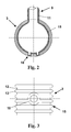
- manifolds 3, 4 are the example of the manifold 3 in the FIGS. 2 to 4 shown.
- FIG. 2 shows a radial section through the manifold 3.
- the clear width of the manifold 3 is 40 mm, the outer diameter 50 mm and the wall thickness is about 1 mm.
- the manifold wall 15 is inside like Externally provided with a corrugated profile. In the manifold 3 open at the same distance ribbed pipe connection piece 11 of a pipe connection. 9
- the pipe connection pieces 11 are provided on a common longitudinal side of the manifold wall 15 and on the opposite longitudinal side of the manifold wall 15 and each pipe connection piece 11 each exactly opposite a so-called bead 10 is provided which FIG. 3 in a plan view.
- the bead 10 contributes to the tension compensation and stiffening of the manifold 3 at. It is designed as a circular increase with approximately the radial dimensions of the pipe connection piece 11. Bead 10 and pipe fittings 11 are formed in a continuous extrusion blow molding process immediately upon extrusion of the manifold tubing 3 and form an integral part thereof. Out FIG. 3 is also the design of the manifold wall 15 to recognize well with a corrugated profile.
- the reference numeral 12 is a "wave trough" of the corrugated profile, and the reference numeral 13 denotes a "wave crest".
- a cheaper production of the manifold 3 is carried out by means of a batch blow molding process, but only pipe pieces with a length corresponding to the blow mold can be produced.
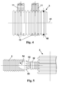
- the wall of the manifold 7 is provided with a plurality of pipe connection pieces 11, which have a center distance of about 35 mm from each other.
- the position of the pipe connection piece 11 and its outer diameter are chosen so that seen in the axial direction always exactly three wave troughs 12 of the corrugated profile are covered by a pipe connection piece 11 and between each three wave crests 13 remain free.
- the center distance of the wave crests is 5 mm.
- the connecting pieces 11 of the pipe connections 9 are also provided with a corrugated profile, which gives them a certain flexibility and at the same time counteracts slipping of the pushed-collector shaft 2.
- connection of a supply or discharge for the water to be heated is always via the distribution pipes 3, 4.
- the relevant ends of the manifold 6, 8 with the sleeve-shaped (in the FIG. 1 shown) connecting elements which are designed for example as a sleeve or elbow.
- the connecting element engages around the lateral surface of the distributor tube 3, 4 and rests with its inner wall on a sealing ring 40, which is inserted into the foremost "wave trough" 12 of the corrugated profile.
- the outermost free end of the connecting element has around its circumference evenly distributed, short longitudinal slots, so that the strip-shaped slot lugs thus produced can be elastically bent inwards in the direction of the longitudinal axis 41 of the distributor tube 3, 4.
- the slot lugs are provided on their inner side with retaining pins, which engage in the bend inwards into a rear trough of the distributor tube corrugated profile.
- FIG. 5 a preferred embodiment of a pipe connection 50 is shown, in which the connecting piece 51 is also formed with a flexible corrugated profile.
- the flexibility gained thereby contributes to improving the frost resistance of the solar collector 1 and prevents slippage of the collector tube 2, as already explained above.
- the free end of the pipe connection piece 51 is provided with a thin-walled, easily deformable thickening 52, which merges into a plurality of Sp Drahnen 53, the ends of which are provided with bead-like crests 55.
- a thin-walled, easily deformable thickening 52 which merges into a plurality of Sp Drahnen 53, the ends of which are provided with bead-like crests 55.
- an axial contact pressure is exerted on the thickening 52, which causes the spreader vanes 53 to spread outwards, against the inner wall 54 of the collector tube 2, and the crests 55 insert into the groove-shaped inner profile of the collector tube 2 and get caught up in it.
- the spreader vanes 53 thus prevent inadvertent release of the connection.
- the pipe connecting piece 51 can also be designed with a comparatively short length, which facilitates and accelerates the assembly of the solar collector.
- the spreading of the spreading tabs 53 is preferably reversible and can be eliminated by removing the pressure from the thickening 52 or by applying a back pressure, and then the collector tube 2 are withdrawn again.
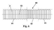
- FIG. 6 shows a longitudinal section of a preferred embodiment of a collector tube 2 for use in a solar collector according to the invention.
- the collector tube 2 is designed as a corrugated tube, and it is cut to length during assembly of the solar collector on site as required by the role.
- the collector tube 2 is provided with marking areas 60 which are distributed at a constant center distance of 50 cm from each other over the entire length of the collector tube 2.
- the marking areas 60 are visually recognizable from the remaining areas by a corrugated profile, which is designed as a fine profile 62 over a length of about 1 cm.
- the "wave crests" are 3 mm apart in the area of the fine profile 62 (as opposed to 5 mm for the coarse profile 61 in the remaining areas).
- the visually recognizable length marking facilitates assembly and reduces waste.
- the marking areas 60 are also used in conjunction with the retaining profiles 7 (see FIG. 1 ) used to stabilize the shape of the absorbent mat 1.
- the collector tube 2 m in the region of the fine wave 62 has a smaller outer diameter of 20 mm and a higher wall thickness of 1 mm, in comparison to the areas of the coarse shaft 61 with an outer diameter of 25 mm and a wall thickness of 0.8 mm.
- the areas of the fine wave 62 are thus characterized by a smaller outer diameter, However, by a comparatively larger wall thickness and by a higher mechanical stability.
- the collector tubes 2 are arranged so that their marking areas 60 each extend in straight lines parallel to the distribution tubes 3, 4. Along these lines, the holding profiles 7 - at a distance of 50 cm - according to the distance of the marking areas 60 from each other - arranged.
- the holding profiles 7 are provided at a distance corresponding to the mounting distance of the collector tubes 2, with semicircular recesses into which the collector tubes 2 are clipped with their Feinwellen- or marking areas 60.
- the collector tubes 2 are thus additionally fixed in the holding profiles 7, but a certain displacement in the direction of the longitudinal axis 63 remains possible. This contributes to the dimensional stability of the absorber mat 1, while maintaining some flexibility to compensate for thermal expansion. In particular, a gradual sliding of the absorber mat 1 is avoided, which is otherwise observed with inclined bearing surfaces, and which is due to the successive expansion and contraction of the collector tubes 2.
Landscapes
- Engineering & Computer Science (AREA)
- Physics & Mathematics (AREA)
- Life Sciences & Earth Sciences (AREA)
- Sustainable Development (AREA)
- Sustainable Energy (AREA)
- Thermal Sciences (AREA)
- Chemical & Material Sciences (AREA)
- Combustion & Propulsion (AREA)
- Mechanical Engineering (AREA)
- General Engineering & Computer Science (AREA)
- Rigid Pipes And Flexible Pipes (AREA)
- Heat-Exchange Devices With Radiators And Conduit Assemblies (AREA)
Applications Claiming Priority (1)
| Application Number | Priority Date | Filing Date | Title |
|---|---|---|---|
| DE102007036749A DE102007036749B4 (de) | 2007-08-03 | 2007-08-03 | Solarkollektor zum Erwärmen einer Flüssigkeit |
Publications (2)
| Publication Number | Publication Date |
|---|---|
| EP2020576A2 true EP2020576A2 (fr) | 2009-02-04 |
| EP2020576A3 EP2020576A3 (fr) | 2013-02-27 |
Family
ID=39938357
Family Applications (1)
| Application Number | Title | Priority Date | Filing Date |
|---|---|---|---|
| EP20080161712 Withdrawn EP2020576A3 (fr) | 2007-08-03 | 2008-08-04 | Collecteur solaire destiné au réchauffement d'un liquide |
Country Status (2)
| Country | Link |
|---|---|
| EP (1) | EP2020576A3 (fr) |
| DE (1) | DE102007036749B4 (fr) |
Cited By (3)
| Publication number | Priority date | Publication date | Assignee | Title |
|---|---|---|---|---|
| EP2284453A3 (fr) * | 2009-08-13 | 2014-01-15 | Roos Freizeitanlagen GmbH | Absorbeur destiné à chauffer un fluide |
| EP2811238A3 (fr) * | 2013-05-28 | 2015-03-11 | Roos Freizeitanlagen GmbH | Tuyau distributeur en tube plastique ondulé comme conduite de liquide pour un collecteur solaire |
| DE102014212481A1 (de) * | 2014-06-27 | 2015-12-31 | Witzenmann Gmbh | Wellrohr für eine Trinkwasserinstallation |
Families Citing this family (2)
| Publication number | Priority date | Publication date | Assignee | Title |
|---|---|---|---|---|
| DE102008058355B4 (de) * | 2008-11-20 | 2011-04-28 | Roos Freizeitanlagen Gmbh | Solarkollektor zum Erwärmen einer Flüssigkeit |
| DE102010016353B4 (de) * | 2010-04-07 | 2021-12-30 | Ihle Maschinenbau Gmbh | Vorrichtung und Verfahren zur Herstellung einer Kapillarrohrmatte |
Citations (2)
| Publication number | Priority date | Publication date | Assignee | Title |
|---|---|---|---|---|
| DE10039111B4 (de) | 2000-08-07 | 2006-03-09 | Triesch, Frank, Dr.-Ing. | Solarabsorber |
| DE102005061008B3 (de) | 2005-12-19 | 2007-03-29 | Roos Freizeitanlagen Gmbh | Solarkollektor zum Erwärmen von Wasser für einen Swimmingpool und dafür geeigneter Bausatz |
Family Cites Families (12)
| Publication number | Priority date | Publication date | Assignee | Title |
|---|---|---|---|---|
| US3578777A (en) * | 1969-06-11 | 1971-05-18 | Koppy Tool Corp | Corrugated tubing |
| US4046136A (en) * | 1975-05-26 | 1977-09-06 | Hitachi Chemical Company, Ltd. | Solar energy collecting device |
| CH621622A5 (en) * | 1978-05-03 | 1981-02-13 | Ind Sgi Ingenieurs Conseils So | Heat exchanger with fluid circulation |
| US4463755A (en) * | 1981-05-18 | 1984-08-07 | Terumo Corporation | Breathing circuit |
| DE8128174U1 (de) * | 1981-09-25 | 1982-01-21 | Verbund-Bau Element GmbH + Co KG, 7000 Stuttgart | Vorrichtung zur erwaermung einer fluessigkeit |
| US5564472A (en) * | 1994-01-10 | 1996-10-15 | Handy And Harman Automotive Group, Inc. | Reinforced flexible corrugated tubing |
| DE19952762A1 (de) * | 1999-11-02 | 2001-05-03 | Mth Moderne Wassertechnik Gmbh | Solaranlage zur Wassertemperierung |
| DE29923057U1 (de) * | 1999-12-31 | 2000-02-17 | Baumann, Roland, Dipl.-Ing. (FH), 89081 Ulm | Leitungssystem zur Verrohrung von Anlagenkomponenten im Bereich der Heizungstechnik |
| US20020017331A1 (en) * | 2000-06-30 | 2002-02-14 | Renaud Michel C. | Variable stiffness bellows |
| US6487768B2 (en) * | 2001-04-16 | 2002-12-03 | Fafco Incorporated | Heat exchanger manufacturing system |
| DE10250305A1 (de) * | 2002-07-08 | 2004-09-23 | Friedrich Udo Müller | Dichtendes Verbindungswellrohr für Solaranlagen und sonstige Anschlüsse |
| DE202006012678U1 (de) * | 2006-08-18 | 2006-11-02 | Gerlach, Joachim | Solarpaneel |
-
2007
- 2007-08-03 DE DE102007036749A patent/DE102007036749B4/de not_active Expired - Fee Related
-
2008
- 2008-08-04 EP EP20080161712 patent/EP2020576A3/fr not_active Withdrawn
Patent Citations (2)
| Publication number | Priority date | Publication date | Assignee | Title |
|---|---|---|---|---|
| DE10039111B4 (de) | 2000-08-07 | 2006-03-09 | Triesch, Frank, Dr.-Ing. | Solarabsorber |
| DE102005061008B3 (de) | 2005-12-19 | 2007-03-29 | Roos Freizeitanlagen Gmbh | Solarkollektor zum Erwärmen von Wasser für einen Swimmingpool und dafür geeigneter Bausatz |
Cited By (3)
| Publication number | Priority date | Publication date | Assignee | Title |
|---|---|---|---|---|
| EP2284453A3 (fr) * | 2009-08-13 | 2014-01-15 | Roos Freizeitanlagen GmbH | Absorbeur destiné à chauffer un fluide |
| EP2811238A3 (fr) * | 2013-05-28 | 2015-03-11 | Roos Freizeitanlagen GmbH | Tuyau distributeur en tube plastique ondulé comme conduite de liquide pour un collecteur solaire |
| DE102014212481A1 (de) * | 2014-06-27 | 2015-12-31 | Witzenmann Gmbh | Wellrohr für eine Trinkwasserinstallation |
Also Published As
| Publication number | Publication date |
|---|---|
| EP2020576A3 (fr) | 2013-02-27 |
| DE102007036749B4 (de) | 2009-08-20 |
| DE102007036749A1 (de) | 2009-02-05 |
Similar Documents
| Publication | Publication Date | Title |
|---|---|---|
| EP1815073B1 (fr) | Absorbeur pour structure de tuyaux ou de canaux et structure de tuyaux ou de canaux muni d'un tel absorbeur | |
| DE3050690C2 (de) | Wärmetauscher mit einer Wärmetauschermatte aus elastomerem Material | |
| DE102008013013A1 (de) | Wärmeübertragendes Rohr | |
| DE102017012049B4 (de) | Erdwärmesonde in Form einer Koaxialsonde mit Doppelrohr-Schlauch und Herstellungsverfahren hierfür | |
| EP2020576A2 (fr) | Collecteur solaire destiné au réchauffement d'un liquide | |
| DE102012213306A1 (de) | Wärmenutzung in Abwasserkanälen | |
| DE102008058355B4 (de) | Solarkollektor zum Erwärmen einer Flüssigkeit | |
| EP1724508B1 (fr) | Tuyau | |
| DE102009048086A1 (de) | Dacheindeckungsplatte zur Gewinnung von Wärmeenergie aus Sonneneinstrahlung | |
| DE202005019499U1 (de) | Beheizung eines Tanks für Harnstoffwasserlösung | |
| CH640932A5 (de) | Waermeuebertragungssystem. | |
| EP2811238B1 (fr) | Tuyau distributeur en tube plastique ondulé comme conduite de liquide pour un collecteur solaire et aussi système de tuyaux distributeurs | |
| EP2520728A1 (fr) | Module encastrable et procédé de montage d'une introduction de lignes d'un dispositif de drainage | |
| EP0374367A1 (fr) | Collecteur solaire | |
| DE102008017659A1 (de) | Speicherbehälter, insbesondere Pufferspeicher für Heizungen | |
| DE4040495A1 (de) | Adapter zum verbinden eines rohres mit einem schlauch | |
| DE102009037064B4 (de) | Absorber zum Erwärmen eines Fluids | |
| DE20219220U1 (de) | Anordnung zum Verbinden von Leitungsabschnitten | |
| DE3205571A1 (de) | Vorrichtung, bei welcher waerme durch hohlfaeden uebertragen wird | |
| DE102010015851A1 (de) | Solarheizung | |
| DE19920457A1 (de) | Verfahren zur Herstellung einer Bauplatte sowie Bauplatte | |
| AT516384B1 (de) | Wärmetauscher | |
| EP0036192A2 (fr) | Installation pour le trasnfert d'une énergie thermique | |
| AT4034U1 (de) | Solaranlage | |
| DE10134271B4 (de) | Rohrprofil für biegsame Leitungen mit ovalen Querschnitt |
Legal Events
| Date | Code | Title | Description |
|---|---|---|---|
| PUAI | Public reference made under article 153(3) epc to a published international application that has entered the european phase |
Free format text: ORIGINAL CODE: 0009012 |
|
| AK | Designated contracting states |
Kind code of ref document: A2 Designated state(s): AT BE BG CH CY CZ DE DK EE ES FI FR GB GR HR HU IE IS IT LI LT LU LV MC MT NL NO PL PT RO SE SI SK TR |
|
| AX | Request for extension of the european patent |
Extension state: AL BA MK RS |
|
| PUAL | Search report despatched |
Free format text: ORIGINAL CODE: 0009013 |
|
| RIC1 | Information provided on ipc code assigned before grant |
Ipc: F24J 2/46 20060101ALI20130109BHEP Ipc: F28F 9/00 20060101ALN20130109BHEP Ipc: F28F 21/00 20060101ALN20130109BHEP Ipc: F24J 2/52 20060101ALN20130109BHEP Ipc: F24J 2/24 20060101AFI20130109BHEP Ipc: F28F 1/00 20060101ALN20130109BHEP |
|
| AK | Designated contracting states |
Kind code of ref document: A3 Designated state(s): AT BE BG CH CY CZ DE DK EE ES FI FR GB GR HR HU IE IS IT LI LT LU LV MC MT NL NO PL PT RO SE SI SK TR |
|
| AX | Request for extension of the european patent |
Extension state: AL BA MK RS |
|
| RIC1 | Information provided on ipc code assigned before grant |
Ipc: F24J 2/24 20060101AFI20130118BHEP Ipc: F28F 21/00 20060101ALN20130118BHEP Ipc: F24J 2/52 20060101ALN20130118BHEP Ipc: F24J 2/46 20060101ALI20130118BHEP Ipc: F28F 1/00 20060101ALN20130118BHEP Ipc: F28F 9/00 20060101ALN20130118BHEP |
|
| 17P | Request for examination filed |
Effective date: 20130817 |
|
| RBV | Designated contracting states (corrected) |
Designated state(s): AT BE BG CH CY CZ DE DK EE ES FI FR GB GR HR HU IE IS IT LI LT LU LV MC MT NL NO PL PT RO SE SI SK TR |
|
| AKX | Designation fees paid |
Designated state(s): AT CH FR GB LI |
|
| REG | Reference to a national code |
Ref country code: DE Ref legal event code: R108 |
|
| REG | Reference to a national code |
Ref country code: DE Ref legal event code: R108 Effective date: 20131030 |
|
| RIC1 | Information provided on ipc code assigned before grant |
Ipc: F28F 21/00 20060101ALN20150317BHEP Ipc: F28F 9/00 20060101ALN20150317BHEP Ipc: F28F 1/08 20060101ALN20150317BHEP Ipc: F24J 2/24 20060101AFI20150317BHEP Ipc: F24J 2/52 20060101ALN20150317BHEP Ipc: F28F 1/00 20060101ALN20150317BHEP Ipc: F24J 2/46 20060101ALI20150317BHEP |
|
| RIC1 | Information provided on ipc code assigned before grant |
Ipc: F28F 21/00 20060101ALN20150415BHEP Ipc: F24J 2/24 20060101AFI20150415BHEP Ipc: F28F 9/00 20060101ALN20150415BHEP Ipc: F28F 1/00 20060101ALN20150415BHEP Ipc: F24J 2/46 20060101ALI20150415BHEP Ipc: F24J 2/52 20060101ALN20150415BHEP Ipc: F28F 1/08 20060101ALN20150415BHEP |
|
| RIC1 | Information provided on ipc code assigned before grant |
Ipc: F24J 2/24 20060101AFI20150521BHEP Ipc: F28F 1/00 20060101ALN20150521BHEP Ipc: F24J 2/52 20060101ALN20150521BHEP Ipc: F28F 1/08 20060101ALN20150521BHEP Ipc: F28F 21/00 20060101ALN20150521BHEP Ipc: F28F 9/00 20060101ALN20150521BHEP Ipc: F24J 2/46 20060101ALI20150521BHEP |
|
| RIC1 | Information provided on ipc code assigned before grant |
Ipc: F28F 1/00 20060101ALN20150526BHEP Ipc: F24J 2/46 20060101ALI20150526BHEP Ipc: F28F 1/08 20060101ALN20150526BHEP Ipc: F28F 9/00 20060101ALN20150526BHEP Ipc: F24J 2/52 20060101ALN20150526BHEP Ipc: F24J 2/24 20060101AFI20150526BHEP Ipc: F28F 21/00 20060101ALN20150526BHEP |
|
| GRAP | Despatch of communication of intention to grant a patent |
Free format text: ORIGINAL CODE: EPIDOSNIGR1 |
|
| INTG | Intention to grant announced |
Effective date: 20150924 |
|
| RIC1 | Information provided on ipc code assigned before grant |
Ipc: F24J 2/24 20060101AFI20151111BHEP Ipc: F28F 1/08 20060101ALN20151111BHEP Ipc: F28F 9/00 20060101ALN20151111BHEP Ipc: F28F 1/00 20060101ALN20151111BHEP Ipc: F28F 21/00 20060101ALN20151111BHEP Ipc: F24J 2/52 20060101ALN20151111BHEP Ipc: F24J 2/46 20060101ALI20151111BHEP |
|
| INTG | Intention to grant announced |
Effective date: 20151202 |
|
| STAA | Information on the status of an ep patent application or granted ep patent |
Free format text: STATUS: THE APPLICATION IS DEEMED TO BE WITHDRAWN |
|
| 18D | Application deemed to be withdrawn |
Effective date: 20160413 |