EP2020586B1 - Dispositif de support pour une charge d'explosifs d'un pénétrateur - Google Patents
Dispositif de support pour une charge d'explosifs d'un pénétrateur Download PDFInfo
- Publication number
- EP2020586B1 EP2020586B1 EP08013492.7A EP08013492A EP2020586B1 EP 2020586 B1 EP2020586 B1 EP 2020586B1 EP 08013492 A EP08013492 A EP 08013492A EP 2020586 B1 EP2020586 B1 EP 2020586B1
- Authority
- EP
- European Patent Office
- Prior art keywords
- penetrator
- charge
- supporting device
- explosive charge
- dividing wall
- Prior art date
- Legal status (The legal status is an assumption and is not a legal conclusion. Google has not performed a legal analysis and makes no representation as to the accuracy of the status listed.)
- Not-in-force
Links
- 239000002360 explosive Substances 0.000 title claims description 69
- 238000005474 detonation Methods 0.000 claims description 28
- 239000000463 material Substances 0.000 claims description 13
- 230000001133 acceleration Effects 0.000 claims description 9
- 238000000034 method Methods 0.000 claims description 4
- 238000007493 shaping process Methods 0.000 claims description 3
- 238000005304 joining Methods 0.000 claims description 2
- 230000002787 reinforcement Effects 0.000 claims description 2
- 230000003213 activating effect Effects 0.000 claims 1
- 239000012634 fragment Substances 0.000 claims 1
- 238000005192 partition Methods 0.000 description 49
- 230000000977 initiatory effect Effects 0.000 description 19
- 230000015572 biosynthetic process Effects 0.000 description 11
- 238000005755 formation reaction Methods 0.000 description 11
- 206010041662 Splinter Diseases 0.000 description 8
- 230000000694 effects Effects 0.000 description 7
- 239000008188 pellet Substances 0.000 description 7
- 239000012791 sliding layer Substances 0.000 description 6
- 229910052751 metal Inorganic materials 0.000 description 4
- 239000002184 metal Substances 0.000 description 4
- 238000006073 displacement reaction Methods 0.000 description 3
- 150000002739 metals Chemical class 0.000 description 3
- 239000004033 plastic Substances 0.000 description 3
- 229920003023 plastic Polymers 0.000 description 3
- 230000035939 shock Effects 0.000 description 3
- RTAQQCXQSZGOHL-UHFFFAOYSA-N Titanium Chemical compound [Ti] RTAQQCXQSZGOHL-UHFFFAOYSA-N 0.000 description 2
- 238000004049 embossing Methods 0.000 description 2
- 230000000149 penetrating effect Effects 0.000 description 2
- 230000008569 process Effects 0.000 description 2
- 230000009467 reduction Effects 0.000 description 2
- 239000010936 titanium Substances 0.000 description 2
- 229910052719 titanium Inorganic materials 0.000 description 2
- RYGMFSIKBFXOCR-UHFFFAOYSA-N Copper Chemical compound [Cu] RYGMFSIKBFXOCR-UHFFFAOYSA-N 0.000 description 1
- 239000004809 Teflon Substances 0.000 description 1
- 229920006362 Teflon® Polymers 0.000 description 1
- 230000009471 action Effects 0.000 description 1
- 238000004026 adhesive bonding Methods 0.000 description 1
- 239000011449 brick Substances 0.000 description 1
- 230000008859 change Effects 0.000 description 1
- 229910052802 copper Inorganic materials 0.000 description 1
- 239000010949 copper Substances 0.000 description 1
- 238000005336 cracking Methods 0.000 description 1
- 230000006378 damage Effects 0.000 description 1
- 230000001934 delay Effects 0.000 description 1
- 230000003111 delayed effect Effects 0.000 description 1
- 230000007613 environmental effect Effects 0.000 description 1
- 238000002474 experimental method Methods 0.000 description 1
- 239000010410 layer Substances 0.000 description 1
- 238000004519 manufacturing process Methods 0.000 description 1
- 238000009304 pastoral farming Methods 0.000 description 1
- 230000035515 penetration Effects 0.000 description 1
- 239000011435 rock Substances 0.000 description 1
- 230000035945 sensitivity Effects 0.000 description 1
- 238000004513 sizing Methods 0.000 description 1
- 238000003466 welding Methods 0.000 description 1
Images

Classifications
-
- F—MECHANICAL ENGINEERING; LIGHTING; HEATING; WEAPONS; BLASTING
- F42—AMMUNITION; BLASTING
- F42B—EXPLOSIVE CHARGES, e.g. FOR BLASTING, FIREWORKS, AMMUNITION
- F42B1/00—Explosive charges characterised by form or shape but not dependent on shape of container
- F42B1/02—Shaped or hollow charges
- F42B1/024—Shaped or hollow charges provided with embedded bodies of inert material
-
- F—MECHANICAL ENGINEERING; LIGHTING; HEATING; WEAPONS; BLASTING
- F42—AMMUNITION; BLASTING
- F42B—EXPLOSIVE CHARGES, e.g. FOR BLASTING, FIREWORKS, AMMUNITION
- F42B12/00—Projectiles, missiles or mines characterised by the warhead, the intended effect, or the material
- F42B12/02—Projectiles, missiles or mines characterised by the warhead, the intended effect, or the material characterised by the warhead or the intended effect
- F42B12/04—Projectiles, missiles or mines characterised by the warhead, the intended effect, or the material characterised by the warhead or the intended effect of armour-piercing type
-
- F—MECHANICAL ENGINEERING; LIGHTING; HEATING; WEAPONS; BLASTING
- F42—AMMUNITION; BLASTING
- F42B—EXPLOSIVE CHARGES, e.g. FOR BLASTING, FIREWORKS, AMMUNITION
- F42B12/00—Projectiles, missiles or mines characterised by the warhead, the intended effect, or the material
- F42B12/02—Projectiles, missiles or mines characterised by the warhead, the intended effect, or the material characterised by the warhead or the intended effect
- F42B12/04—Projectiles, missiles or mines characterised by the warhead, the intended effect, or the material characterised by the warhead or the intended effect of armour-piercing type
- F42B12/10—Projectiles, missiles or mines characterised by the warhead, the intended effect, or the material characterised by the warhead or the intended effect of armour-piercing type with shaped or hollow charge
-
- F—MECHANICAL ENGINEERING; LIGHTING; HEATING; WEAPONS; BLASTING
- F42—AMMUNITION; BLASTING
- F42B—EXPLOSIVE CHARGES, e.g. FOR BLASTING, FIREWORKS, AMMUNITION
- F42B12/00—Projectiles, missiles or mines characterised by the warhead, the intended effect, or the material
- F42B12/02—Projectiles, missiles or mines characterised by the warhead, the intended effect, or the material characterised by the warhead or the intended effect
- F42B12/20—Projectiles, missiles or mines characterised by the warhead, the intended effect, or the material characterised by the warhead or the intended effect of high-explosive type
- F42B12/201—Projectiles, missiles or mines characterised by the warhead, the intended effect, or the material characterised by the warhead or the intended effect of high-explosive type characterised by target class
- F42B12/204—Projectiles, missiles or mines characterised by the warhead, the intended effect, or the material characterised by the warhead or the intended effect of high-explosive type characterised by target class for attacking structures, e.g. specific buildings or fortifications, ships or vehicles
Definitions
- the invention relates to a support device for an explosive charge of a penetrator, the explosive charge consists of at least one front and one rear part charge, which are arranged inside the shell of the penetrator behind the other, wherein between the part charges a cross-section of the explosive charge covering and attached to the shell of the penetrator Partition is arranged and the ignition of the explosive charge emanates from the rear part of the charge.
- Penetrators are active systems which, due to their structural design, are suitable for penetrating resistant structures such as building walls made of brick or concrete or even rock.
- penetrator equipped with a hollow charge When combating such structures by a penetrator equipped with a hollow charge, the effect of the directed hollow charge is no longer in the foreground. Rather, it is of interest that the penetrator after penetrating the structure is still able to unfold in the space behind the structure as high as possible Blast- and / or splintering performance. Otherwise, the mission can not be adequately fulfilled.
- the invention is based on the problem that on the one hand high-strength and thick structures must be perforated. This requires fast and slim long penetrators with a correspondingly long explosive charge.
- the penetrator and thus also the explosive charge during perforation undergoes a very high negative acceleration, which causes the explosive charge to the penetrator tip moves as far as allow the cavities present in the Penetratorspitze. In particular, the cavity located in front of the shaped charge liner is affected. This movement of the explosive charge towards the penetrator tip and thus away from the ignition device involves the risk that distances in particular from the booster charge to Explosive charge become too large and a safe initiation of the explosive charge is no longer guaranteed.
- a support of the explosive charge by the usually made of soft and ductile metal insert of the shaped charge fails because of their insufficient resistance to the accelerations occurring.
- the load of the insert through the long explosive column in the penetrator would lead to an inversion of the insert, at most until it rests against the inner wall of the shell.
- the invention is based on the idea to find a suitable support of the explosive charge with respect to the acceleration forces occurring.
- the rear explosive charge from which the ignition emanates, is designed as a shaped charge with a metallic insert. Although this insert supports the rear explosive charge at rest, it is dimensioned so that it would fold in the direction of the tip of the active charge in the case of a target penetration. In this case, since the explosive charge would move together with the liner, a clearance is created between the ignition distributor plate and the explosive, and the explosive charge can no longer be properly initiated.
- the DE 695 09 332 T2 describes a projectile for the destruction of hard targets.
- a Penetratorgeophuse several explosive charges are arranged, which are equipped with their own ignition devices. The ignition of the explosive charges is inevitably serial from back to front.
- the individual explosive charges are partitioned off from one another by partitions. The partitions serve to support the individual explosive charges with each other and are in terms of sizing and material selection such that when initiating one of the explosive charges in any case, the shell is destroyed before the partition. Only in this way, at the same time a blast or splintering effect of the individual explosive charges and at the same time a propulsion of the remaining Penetratorteils be achieved. However, the achievable effect is limited to the implementable amount of explosive each successive detonated charges. A simultaneous initiation of all individual explosive charges is not possible hereby. Thus, this embodiment of a support for solving the above problems is not suitable.
- the invention has for its object to find a support for the explosive charge of a penetrator, which avoids the problems mentioned and allows the deployment of the power of the entire explosive charge of the penetrator at a desired time.
- the object of the present invention is that at least one separating wall serving as a supporting device and dividing the explosive charge into partial charges (HE1, HE2) and supporting itself against the envelope in the case of a high negative acceleration of the penetrator is shaped and / or formed such a material is that upon initiation of the back partial charge in each case, the partition wall is disassembled in front of the shell.
- the partition wall is not an obstacle to the detonation front, so that the entire partial charges are completely detonated.
- a sliding layer is advantageously arranged between the front part charge and the shell, which extends from the partition to the top of the Penetrators extends and which upon impact of the penetrator on the target, the movement of the front part of the charge into the tip of the penetrator supported.
- the sliding layer may also have an embossing on the surface adjacent to the shell, whereby splinters of desired size can be generated.
- a plurality of spaced-apart partitions may be provided in the explosive charge, which support the entire explosive charge and only the foremost small part charge is held by the insert. In this case, no sliding layer is used.
- the explosive charge of a penetrator is divided into at least two partial charges, which are separated by a respective weaker against the shell partition designed, the partitions are firmly connected to the shell to be able to support the onloading partial charge.
- the support must of course be able to hold only this part of the explosive charge.
- the partition in the direction of the rear partial charge is simply or multiply convex, wherein the formation of the partition can be made, for example, conical or hemispherical.
- the function of the hooking of the partition in the shell is supported.
- the inherently elastic explosive charge column is axially stabilized in itself.
- the dividing wall has a detonation waveguide in the respective central area.
- This can be realized as a separate component or else in that the partition has a greater thickness in the respective central region than in the outer region. so that can focus the detonation wave striking the bulkhead from behind onto the next section of the explosive charge.
- auxiliary charge is integrated in the partition wall. These may be arranged as a circle around the center of the insert around as evenly distributed individual charges. An embodiment in the form of a single annular charge can just as well be used. The initiation takes place by means of the detonation wave coming from behind onto the dividing wall.
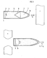
- FIG. 1 For understanding the processes occurring at the moment of the impact of a penetrator on a target Z is described in the FIG. 1 in the upper half of a penetrator 1 before the target passage and in the lower half of a penetrator after the target passage in each case in a sectional view.
- the ignition system 3 Within the shell 2 of the penetrator is located at the rear of the ignition system 3, which ignites the explosive charge 5 in the case of initiation on the booster charge 4. It is assumed in the example of only one explosive charge within the shell 2 of the penetrator 1 .
- the insert 6 With the explosive charge 5, the insert 6 is positively connected, so that explosive charge and insert together form a shaped charge with effect in the direction of the tip 2a of the penetrator.
- the insert is made of relatively soft and ductile copper and is therefore unable to withstand higher loads. It is also assumed that the envelope of the penetrator is long and slender.
- the penetrator hits the target Z at a speed v 0 , perforates it and then moves on at the significantly reduced speed v 1 . Due to the enormous delay that occurs, the pressure of the explosive charge 5 on the insert 6 can become so great that it comes loose from its holder and inverts in the direction of the tip 2a. The explosive charge slides together with the deforming insert forward until the previously existing cavity 7, which actually serves the formation of the shaped charge spine, is filled. With lower delays different intermediate states are possible. This creates on the back of the explosive charge 5, a new cavity 8, whose volume is about as large as the volume loss of the front cavity 7.
- a structurally offering change in the form of a reinforced support of the insert on the shell 2 is not a solution, since it would be a significant reduction in performance of the shaped charge would be connected.
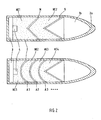
- the explosive charge 5 is off FIG. 1 divided into two or more partial charges HE1, ..., HE4 whose Loads so each serving as supports dividing walls A, A1, ..., A3 is divided.
- the number of dividing walls depends on the length of the penetrator and on the expected negative accelerations in use.
- the partitions cover the entire inner cross section of the shell 2 of the penetrator. With regard to the shape of a variety of configurations are possible.
- the partitions do not pose an obstacle to the shockwave entering the bulkhead after initiation of the explosive charge (generated by the detonation front of the explosive charge) as the shockwave front continues within the bulkhead materials and triggers a new detonation on the exit side in the explosive charge.
- FIG. 2 initially the cone or dome-shaped partition shown.
- Other examples are in the FIGS. 4 and 5 shown without the design of the partition would be limited to the examples shown.
- the dividing walls A, A1,..., A3 used as supports open in the direction of the insert 6, so that the edge of the dividing wall can be supported in each case against the shell 2 of the penetrator and can catch it.
- the entire, in itself very elastic explosive charge is stabilized by the partitions axially in itself.
- the material for the partitions high strength and low density metals such as titanium or other materials having similar properties are well suited.
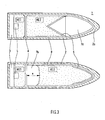
- FIG. 3 Especially with long penetrators, which are exposed to high negative accelerations, offers a solution, as in the FIG. 3 is shown. It is deliberately omitted to support the entire explosive charge. Instead, the explosive charge is divided by means of a correspondingly designed partition A into two different sized partial charges HE1 and HE2. Thus, only the smaller rear partial charge HE1 is supported independently of the front partial charge HE2. So the partition A does not have to be made particularly massive. Rather, a constructive secure support must be achieved. This is achieved for example by a circumferential reinforcement of the edge of the partition. As a connection to the shell itself usually sufficient gluing, welding or other joining technique with similar strength.
- the front partial charge HE2 due to strong negative acceleration slips forward until it rests against the inner wall of the tip 2a of the penetrator, it is expedient to support this process by means of a thin sliding layer 8.
- This sliding layer 8 usually clothes the interior of the penetrator from the partition wall A to the tip 2a.
- Suitable materials for this overlay are plastics with a low coefficient of friction on the surface such as Teflon.
- the sliding layer may have on its outer surface an embossing, which supports the formation of splitters of desired size upon detonation of the partial charge HE2.
- the initiation of the rear partial charge HE1 via the booster charge takes place. since the partition wall A supports this partial charge HE1 in the target passage, a reliable initiation of this partial charge HE1 is ensured. Due to the displacement into the previously existing cavity 7a in the tip 2a and the simultaneous formation of a further cavity 7b behind the partial charge HE2, the front partial charge HE2 now has a distance x from the dividing wall A. This distance is so great that it can not be bridged by a booster charge 4. However, since the rear partial charge HE1 can be safely initiated, the detonation shock generated by this partial charge for the inevitable follow-up initiation of the front partial charge HE2 over the Partition A off.
- the partition allows this type of ignition by their nature in terms of dimensioning and the choice of material. Both factors are chosen so that in each case the partition A is decomposed in front of the shell 2. Thus, the ignition takes place prior to the disassembly of the shell 2.
- the effect of the initiated partial charges HE1 and HE2 in the target is then no longer the spike formation of a shaped charge as shown in FIG FIG. 3 upper half, but the radial splitter delivery.
- splinter generation is limited only in the area of the cavity 7b. For this, however, the area of the cavity 7a existing before the displacement of the partial charge HE2 is included in the splinter formation. Overall, there is thus no reduction in performance due to the shift.
- the two partial charges do not necessarily consist of the same explosive charge. In this advantageous manner, a vote between initiation sensitivity and performance can be made.
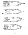
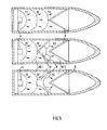
- FIG. 4 It is shown how the design of the partition A can influence the support of the initiation.
- Various examples are in the four drawings of FIG. 4 illustrated, other embodiments are of course conceivable.
- the top example corresponds to the configuration from the FIG. 3 ,
- the partition may be designed as a flat plate A10, which acts at short distances x as a flying plate. At longer distances natural splinters form. Splinter formation can be influenced by a further material layer applied to the dividing wall.
- the two lower drawings of the FIG. 5 show, however, that the same principle is also applicable to penetrators with at least one partition A.
- the partition wall A is fitted in its central region with a detonation shaft 9 or the partition A itself is formed in its central part so that the deflection of the detonation front takes place as in a detonation 9.
- the with a detonation shaft 9 supplemented partition A is conveniently placed in the vicinity of the insert.
- at least the edge of the partition is inclined towards the tip of the penetrator.
- Other partitions in the above-described design can also be used depending on the length of the penetrator.
- the course of the detonation fronts 21, 22, 23 and 31, 32, 33 is shown in dashed lines. In both cases, the detonation front approximately perpendicular to the insert 6, so that the optimum performance can be implemented.
- a partial charge HE1 designed for blast action in the rear area of the penetrator in order to achieve a preferably radial effect after the passage of the target.
- Their typical detonation pressures are lower than those of explosive charges designed for use with shaped charges.
- the latter is particularly well suited for the front partial charge HE2. In this way, not only the performance of the total charge is optimized, but it must also be the detonation shaft 9 is not disproportionately strong.
- pellets ie compact explosive charges
- FIG. 6 An extension of the lower drawing of the FIG. 5 illustrated embodiment is in two exemplary variants in the FIG. 6 played.
- pellets ie compact explosive charges
- the advantages of the pellets can be utilized.
- front partial charge HE2 detonation fronts emanating from the pellets form, which strike the insert 6 approximately perpendicularly.
- the section A '- B' shows an example of a possible arrangement of the pellets in the partition A. It should be noted, however, that on the one hand enough pellets are provided to achieve the most homogeneous detonation front and on the other hand, the strength of the partition is not limited too much.
Landscapes
- Engineering & Computer Science (AREA)
- General Engineering & Computer Science (AREA)
- Chemical & Material Sciences (AREA)
- Combustion & Propulsion (AREA)
- Portable Nailing Machines And Staplers (AREA)
- Crushing And Pulverization Processes (AREA)
Claims (11)
- Dispositif de protection pour une charge explosive (5) d'une cartouche perforante (1) dont la charge perforante se compose d'au moins une charge partielle avant (HE2) et d'une charge partielle arrière (HE1), lesquelles sont disposées l'une derrière l'autre à l'intérieur de l'enveloppe (2) de la cartouche perforante, une paroi de séparation recouvrant la section transversale de la charge explosive et fixée à l'enveloppe (2) de la cartouche perforante étant disposée entre les charges partielles et l'allumage de la charge explosive partant de la charge partielle arrière (HE1), caractérisé en ce qu'au moins une paroi de séparation (A, A1, A2, A3) servant de dispositif de protection et divisant la charge explosive en charges partielles (HE1, HE2) et s'appuyant contre l'enveloppe (2) dans le cas d'une accélération négative élevée de la cartouche perforante est façonnée de telle sorte et/ou se compose d'un tel matériau que lors de l'initiation (3, 4) de la charge partielle arrière (HE1), la paroi de séparation (A, A1, A2, A3) est dans tous les cas détruite avant l'enveloppe (2).
- Dispositif de protection selon la revendication 1, caractérisé en ce que dans le cas de l'appui seulement d'une charge partielle (HE1), une couche de glissement (8) est disposée entre la charge partielle avant (HE2) et l'enveloppe (2) de la cartouche perforante, laquelle s'étend de la paroi de séparation (A) jusque dans la pointe (2a) de la cartouche perforante (1).
- Dispositif de protection selon la revendication 2, caractérisé en ce que la couche de glissement (8) présente une pré-gravure pour former des tailles de fragments définies.
- Dispositif de protection selon l'une des revendications 1 à 3, caractérisé en ce que plusieurs parois de séparation (A1, A2, A3) espacées les unes des autres sont prévues dans la charge explosive.
- Dispositif de protection selon l'une des revendications 1 à 4, caractérisé en ce que la paroi de séparation (A) présente sur le bord un renfort périphérique et elle est fixée à demeure avec l'enveloppe (2) de la cartouche perforante au moyen d'un collage, d'un soudage ou d'une autre technique d'assemblage qui présente une solidité équivalente.
- Dispositif de protection selon l'une des revendications 1 à 5, caractérisé en ce que la paroi de séparation (A) est de forme convexe simple (A11) ou multiple (A13) en direction de la charge partielle arrière (HE1).
- Dispositif de protection selon la revendication 6, caractérisé en ce que le façonnage de la paroi de séparation (A) est réalisé en forme conique (A12) ou en forme de demi-sphère.
- Dispositif de protection selon l'une des revendications 1 à 6, caractérisé en ce que la paroi de séparation (A) présente un guide d'onde de détonation (9) dans la zone centrale correspondante.
- Dispositif de protection selon l'une des revendications 1 à 6, caractérisé en ce que la paroi de séparation (A) présente dans la zone centrale correspondante une épaisseur supérieure à celle dans la zone extérieure.
- Dispositif de protection selon l'une des revendications 1 à 9, caractérisé en ce qu'au moins une charge auxiliaire (10) compacte est disposée dans la zone extérieure de la paroi de séparation (A).
- Dispositif de protection selon la revendication 10, caractérisé en ce que la charge auxiliaire (10) compacte est configurée en forme d'anneau.
Applications Claiming Priority (1)
| Application Number | Priority Date | Filing Date | Title |
|---|---|---|---|
| DE200710035551 DE102007035551B4 (de) | 2007-07-28 | 2007-07-28 | Stützvorrichtung für eine Sprengladung eines Penetrators |
Publications (3)
| Publication Number | Publication Date |
|---|---|
| EP2020586A2 EP2020586A2 (fr) | 2009-02-04 |
| EP2020586A3 EP2020586A3 (fr) | 2012-12-05 |
| EP2020586B1 true EP2020586B1 (fr) | 2014-01-15 |
Family
ID=39944429
Family Applications (1)
| Application Number | Title | Priority Date | Filing Date |
|---|---|---|---|
| EP08013492.7A Not-in-force EP2020586B1 (fr) | 2007-07-28 | 2008-07-26 | Dispositif de support pour une charge d'explosifs d'un pénétrateur |
Country Status (3)
| Country | Link |
|---|---|
| EP (1) | EP2020586B1 (fr) |
| DE (1) | DE102007035551B4 (fr) |
| ES (1) | ES2457417T3 (fr) |
Families Citing this family (3)
| Publication number | Priority date | Publication date | Assignee | Title |
|---|---|---|---|---|
| DE202009015942U1 (de) | 2009-11-21 | 2010-02-25 | TDW Gesellschaft für verteidigungstechnische Wirksysteme mbH | Zündvorrichtung für die Sprengladung eines Penetrators |
| DE102010018187B4 (de) | 2010-04-26 | 2012-04-19 | TDW Gesellschaft für verteidigungstechnische Wirksysteme mbH | Zündvorrichtung für einen Penetrator |
| DE102012012409B4 (de) * | 2012-06-25 | 2015-05-13 | TDW Gesellschaft für verteidigungstechnische Wirksysteme mbH | Penetrator mit einer Hohlladung |
Citations (1)
| Publication number | Priority date | Publication date | Assignee | Title |
|---|---|---|---|---|
| DE69509332T2 (de) * | 1994-09-06 | 1999-12-02 | Rockwell International Corp., Seal Beach | Geschoss für die Zerstörung von harten Zielen, die tief vergraben sind |
Family Cites Families (10)
| Publication number | Priority date | Publication date | Assignee | Title |
|---|---|---|---|---|
| FR971379A (fr) * | 1940-04-24 | 1951-01-16 | Obus de rupture perfectionné | |
| US2426997A (en) * | 1941-03-10 | 1947-09-09 | John C Gray | Projectile |
| GB1301081A (en) * | 1943-03-22 | 1972-12-29 | William Beardmore & Co Ltd | Improvements in or relating to gun fired high explosive projectiles |
| FR2410243A1 (fr) * | 1977-11-24 | 1979-06-22 | Serat | Perfectionnements apportes aux charges creuses |
| DE3800975A1 (de) * | 1988-01-15 | 1989-07-27 | Bongers Hermann | Panzergeschoss mit additiver durchschlagswirkung |
| DE19517610C2 (de) * | 1995-05-13 | 1997-04-17 | Diehl Gmbh & Co | Lenkrakete mit einem Splittergefechtskopf |
| EP0950870B1 (fr) | 1998-04-18 | 2003-12-03 | TDW Gesellschaft für verteidigungstechnische Wirksysteme mbH | Charge militaire à effet multiple |
| SE519758C2 (sv) * | 2000-07-03 | 2003-04-08 | Bofors Weapon Sys Ab | Arrangemang för att bekämpa mål med eller utav RSV- effektuerande verkan |
| US6601517B1 (en) * | 2001-10-31 | 2003-08-05 | The United States Of America As Represented By The Secretary Of The Navy | Super-cavitating penetrator warhead |
| US7363862B2 (en) * | 2005-05-27 | 2008-04-29 | United States Of America As Represented By The Secretary Of The Army | Multi-purpose single initiated tandem warhead |
-
2007
- 2007-07-28 DE DE200710035551 patent/DE102007035551B4/de not_active Expired - Fee Related
-
2008
- 2008-07-26 ES ES08013492T patent/ES2457417T3/es active Active
- 2008-07-26 EP EP08013492.7A patent/EP2020586B1/fr not_active Not-in-force
Patent Citations (1)
| Publication number | Priority date | Publication date | Assignee | Title |
|---|---|---|---|---|
| DE69509332T2 (de) * | 1994-09-06 | 1999-12-02 | Rockwell International Corp., Seal Beach | Geschoss für die Zerstörung von harten Zielen, die tief vergraben sind |
Also Published As
| Publication number | Publication date |
|---|---|
| ES2457417T3 (es) | 2014-04-25 |
| DE102007035551B4 (de) | 2010-04-22 |
| EP2020586A3 (fr) | 2012-12-05 |
| DE102007035551A1 (de) | 2009-01-29 |
| EP2020586A2 (fr) | 2009-02-04 |
Similar Documents
| Publication | Publication Date | Title |
|---|---|---|
| DE19825260B4 (de) | Anordnung zum Schutz von Objekten gegen geformte Ladungen | |
| DE3628622C1 (de) | Vorrichtung zur Erzeugung sprenggeformter Projektile | |
| EP1893935B1 (fr) | Projectile ou ogive | |
| EP1912037B1 (fr) | Charge d'action cylindrique | |
| DE2107102A1 (de) | Sprengkopf mit zundungsabhangiger Steuerung der Richtung der Sprengwirkung | |
| EP2239536B1 (fr) | Système d'allumage réglable pour une tête militaire | |
| DE3235404A1 (de) | Sprengladung | |
| EP2024706B1 (fr) | Projectile, corps actif ou ogive destiné à combattre des objectifs massifs, structurés et plats | |
| EP2325596B1 (fr) | Pénétrateur avec un chargement explosif et un dispositif d'allumage | |
| DE102007035551B4 (de) | Stützvorrichtung für eine Sprengladung eines Penetrators | |
| DE1910779C3 (de) | Hohlladung | |
| DE3501649C2 (fr) | ||
| DE4135392C2 (de) | Gefechtskopf | |
| DE102007063681B4 (de) | Stützvorrichtung für eine Sprengladung eines Penetrators | |
| DE2841040A1 (de) | Sprengkoerper mit einer durch einen zuender zuendbaren sprengladung | |
| EP1936319B1 (fr) | Pénétrateur et procédé de production d'un tel pénétrateur | |
| DE4126793C1 (de) | Tandemgefechtskopf | |
| DE102010027580B4 (de) | Gefechtskopf | |
| DE102011010351A1 (de) | Umschaltbare Wirkladung | |
| DE102005057254B4 (de) | Penetrationsgeschoss und Verfahren zur Erzeugung eines solchen Geschosses | |
| DE10222184B4 (de) | Gefechtskopf | |
| DE102010018187B4 (de) | Zündvorrichtung für einen Penetrator | |
| DE3932825C2 (fr) | ||
| DE3920015C1 (de) | Gefechtskopf | |
| DE1106646B (de) | Hohlladung |
Legal Events
| Date | Code | Title | Description |
|---|---|---|---|
| PUAI | Public reference made under article 153(3) epc to a published international application that has entered the european phase |
Free format text: ORIGINAL CODE: 0009012 |
|
| AK | Designated contracting states |
Kind code of ref document: A2 Designated state(s): AT BE BG CH CY CZ DE DK EE ES FI FR GB GR HR HU IE IS IT LI LT LU LV MC MT NL NO PL PT RO SE SI SK TR |
|
| AX | Request for extension of the european patent |
Extension state: AL BA MK RS |
|
| PUAL | Search report despatched |
Free format text: ORIGINAL CODE: 0009013 |
|
| AK | Designated contracting states |
Kind code of ref document: A3 Designated state(s): AT BE BG CH CY CZ DE DK EE ES FI FR GB GR HR HU IE IS IT LI LT LU LV MC MT NL NO PL PT RO SE SI SK TR |
|
| AX | Request for extension of the european patent |
Extension state: AL BA MK RS |
|
| RIC1 | Information provided on ipc code assigned before grant |
Ipc: F42B 1/024 20060101ALN20121101BHEP Ipc: F42B 12/10 20060101ALN20121101BHEP Ipc: F42B 12/20 20060101AFI20121101BHEP Ipc: F42B 12/04 20060101ALI20121101BHEP |
|
| 17P | Request for examination filed |
Effective date: 20130511 |
|
| AKX | Designation fees paid |
Designated state(s): AT BE BG CH CY CZ DE DK EE ES FI FR GB GR HR HU IE IS IT LI LT LU LV MC MT NL NO PL PT RO SE SI SK TR |
|
| RIC1 | Information provided on ipc code assigned before grant |
Ipc: F42B 1/024 20060101ALN20130722BHEP Ipc: F42B 12/10 20060101ALN20130722BHEP Ipc: F42B 12/04 20060101ALI20130722BHEP Ipc: F42B 12/20 20060101AFI20130722BHEP |
|
| GRAP | Despatch of communication of intention to grant a patent |
Free format text: ORIGINAL CODE: EPIDOSNIGR1 |
|
| INTG | Intention to grant announced |
Effective date: 20130913 |
|
| GRAS | Grant fee paid |
Free format text: ORIGINAL CODE: EPIDOSNIGR3 |
|
| GRAA | (expected) grant |
Free format text: ORIGINAL CODE: 0009210 |
|
| AK | Designated contracting states |
Kind code of ref document: B1 Designated state(s): AT BE BG CH CY CZ DE DK EE ES FI FR GB GR HR HU IE IS IT LI LT LU LV MC MT NL NO PL PT RO SE SI SK TR |
|
| REG | Reference to a national code |
Ref country code: CH Ref legal event code: EP Ref country code: GB Ref legal event code: FG4D Free format text: NOT ENGLISH |
|
| REG | Reference to a national code |
Ref country code: AT Ref legal event code: REF Ref document number: 650027 Country of ref document: AT Kind code of ref document: T Effective date: 20140215 |
|
| REG | Reference to a national code |
Ref country code: IE Ref legal event code: FG4D Free format text: LANGUAGE OF EP DOCUMENT: GERMAN |
|
| REG | Reference to a national code |
Ref country code: DE Ref legal event code: R096 Ref document number: 502008011222 Country of ref document: DE Effective date: 20140227 |
|
| REG | Reference to a national code |
Ref country code: ES Ref legal event code: FG2A Ref document number: 2457417 Country of ref document: ES Kind code of ref document: T3 Effective date: 20140425 |
|
| REG | Reference to a national code |
Ref country code: SE Ref legal event code: TRGR |
|
| REG | Reference to a national code |
Ref country code: NL Ref legal event code: VDEP Effective date: 20140115 |
|
| REG | Reference to a national code |
Ref country code: LT Ref legal event code: MG4D |
|
| PG25 | Lapsed in a contracting state [announced via postgrant information from national office to epo] |
Ref country code: LT Free format text: LAPSE BECAUSE OF FAILURE TO SUBMIT A TRANSLATION OF THE DESCRIPTION OR TO PAY THE FEE WITHIN THE PRESCRIBED TIME-LIMIT Effective date: 20140115 Ref country code: IS Free format text: LAPSE BECAUSE OF FAILURE TO SUBMIT A TRANSLATION OF THE DESCRIPTION OR TO PAY THE FEE WITHIN THE PRESCRIBED TIME-LIMIT Effective date: 20140515 Ref country code: NO Free format text: LAPSE BECAUSE OF FAILURE TO SUBMIT A TRANSLATION OF THE DESCRIPTION OR TO PAY THE FEE WITHIN THE PRESCRIBED TIME-LIMIT Effective date: 20140415 |
|
| PG25 | Lapsed in a contracting state [announced via postgrant information from national office to epo] |
Ref country code: FI Free format text: LAPSE BECAUSE OF FAILURE TO SUBMIT A TRANSLATION OF THE DESCRIPTION OR TO PAY THE FEE WITHIN THE PRESCRIBED TIME-LIMIT Effective date: 20140115 Ref country code: NL Free format text: LAPSE BECAUSE OF FAILURE TO SUBMIT A TRANSLATION OF THE DESCRIPTION OR TO PAY THE FEE WITHIN THE PRESCRIBED TIME-LIMIT Effective date: 20140115 Ref country code: CY Free format text: LAPSE BECAUSE OF FAILURE TO SUBMIT A TRANSLATION OF THE DESCRIPTION OR TO PAY THE FEE WITHIN THE PRESCRIBED TIME-LIMIT Effective date: 20140115 Ref country code: PT Free format text: LAPSE BECAUSE OF FAILURE TO SUBMIT A TRANSLATION OF THE DESCRIPTION OR TO PAY THE FEE WITHIN THE PRESCRIBED TIME-LIMIT Effective date: 20140515 |
|
| PG25 | Lapsed in a contracting state [announced via postgrant information from national office to epo] |
Ref country code: LV Free format text: LAPSE BECAUSE OF FAILURE TO SUBMIT A TRANSLATION OF THE DESCRIPTION OR TO PAY THE FEE WITHIN THE PRESCRIBED TIME-LIMIT Effective date: 20140115 Ref country code: HR Free format text: LAPSE BECAUSE OF FAILURE TO SUBMIT A TRANSLATION OF THE DESCRIPTION OR TO PAY THE FEE WITHIN THE PRESCRIBED TIME-LIMIT Effective date: 20140115 |
|
| REG | Reference to a national code |
Ref country code: DE Ref legal event code: R097 Ref document number: 502008011222 Country of ref document: DE |
|
| PG25 | Lapsed in a contracting state [announced via postgrant information from national office to epo] |
Ref country code: RO Free format text: LAPSE BECAUSE OF FAILURE TO SUBMIT A TRANSLATION OF THE DESCRIPTION OR TO PAY THE FEE WITHIN THE PRESCRIBED TIME-LIMIT Effective date: 20140115 Ref country code: DK Free format text: LAPSE BECAUSE OF FAILURE TO SUBMIT A TRANSLATION OF THE DESCRIPTION OR TO PAY THE FEE WITHIN THE PRESCRIBED TIME-LIMIT Effective date: 20140115 Ref country code: CZ Free format text: LAPSE BECAUSE OF FAILURE TO SUBMIT A TRANSLATION OF THE DESCRIPTION OR TO PAY THE FEE WITHIN THE PRESCRIBED TIME-LIMIT Effective date: 20140115 Ref country code: EE Free format text: LAPSE BECAUSE OF FAILURE TO SUBMIT A TRANSLATION OF THE DESCRIPTION OR TO PAY THE FEE WITHIN THE PRESCRIBED TIME-LIMIT Effective date: 20140115 |
|
| PLBE | No opposition filed within time limit |
Free format text: ORIGINAL CODE: 0009261 |
|
| STAA | Information on the status of an ep patent application or granted ep patent |
Free format text: STATUS: NO OPPOSITION FILED WITHIN TIME LIMIT |
|
| PG25 | Lapsed in a contracting state [announced via postgrant information from national office to epo] |
Ref country code: PL Free format text: LAPSE BECAUSE OF FAILURE TO SUBMIT A TRANSLATION OF THE DESCRIPTION OR TO PAY THE FEE WITHIN THE PRESCRIBED TIME-LIMIT Effective date: 20140115 Ref country code: SK Free format text: LAPSE BECAUSE OF FAILURE TO SUBMIT A TRANSLATION OF THE DESCRIPTION OR TO PAY THE FEE WITHIN THE PRESCRIBED TIME-LIMIT Effective date: 20140115 |
|
| 26N | No opposition filed |
Effective date: 20141016 |
|
| REG | Reference to a national code |
Ref country code: DE Ref legal event code: R097 Ref document number: 502008011222 Country of ref document: DE Effective date: 20141016 |
|
| PG25 | Lapsed in a contracting state [announced via postgrant information from national office to epo] |
Ref country code: LU Free format text: LAPSE BECAUSE OF FAILURE TO SUBMIT A TRANSLATION OF THE DESCRIPTION OR TO PAY THE FEE WITHIN THE PRESCRIBED TIME-LIMIT Effective date: 20140726 |
|
| REG | Reference to a national code |
Ref country code: IE Ref legal event code: MM4A |
|
| PG25 | Lapsed in a contracting state [announced via postgrant information from national office to epo] |
Ref country code: SI Free format text: LAPSE BECAUSE OF FAILURE TO SUBMIT A TRANSLATION OF THE DESCRIPTION OR TO PAY THE FEE WITHIN THE PRESCRIBED TIME-LIMIT Effective date: 20140115 |
|
| REG | Reference to a national code |
Ref country code: FR Ref legal event code: PLFP Year of fee payment: 8 |
|
| PG25 | Lapsed in a contracting state [announced via postgrant information from national office to epo] |
Ref country code: IE Free format text: LAPSE BECAUSE OF NON-PAYMENT OF DUE FEES Effective date: 20140726 |
|
| REG | Reference to a national code |
Ref country code: AT Ref legal event code: MM01 Ref document number: 650027 Country of ref document: AT Kind code of ref document: T Effective date: 20140726 |
|
| PG25 | Lapsed in a contracting state [announced via postgrant information from national office to epo] |
Ref country code: AT Free format text: LAPSE BECAUSE OF NON-PAYMENT OF DUE FEES Effective date: 20140726 |
|
| PG25 | Lapsed in a contracting state [announced via postgrant information from national office to epo] |
Ref country code: MC Free format text: LAPSE BECAUSE OF FAILURE TO SUBMIT A TRANSLATION OF THE DESCRIPTION OR TO PAY THE FEE WITHIN THE PRESCRIBED TIME-LIMIT Effective date: 20140115 |
|
| PG25 | Lapsed in a contracting state [announced via postgrant information from national office to epo] |
Ref country code: BG Free format text: LAPSE BECAUSE OF FAILURE TO SUBMIT A TRANSLATION OF THE DESCRIPTION OR TO PAY THE FEE WITHIN THE PRESCRIBED TIME-LIMIT Effective date: 20140115 |
|
| PG25 | Lapsed in a contracting state [announced via postgrant information from national office to epo] |
Ref country code: IT Free format text: LAPSE BECAUSE OF FAILURE TO SUBMIT A TRANSLATION OF THE DESCRIPTION OR TO PAY THE FEE WITHIN THE PRESCRIBED TIME-LIMIT Effective date: 20140115 Ref country code: GR Free format text: LAPSE BECAUSE OF FAILURE TO SUBMIT A TRANSLATION OF THE DESCRIPTION OR TO PAY THE FEE WITHIN THE PRESCRIBED TIME-LIMIT Effective date: 20140416 Ref country code: MT Free format text: LAPSE BECAUSE OF FAILURE TO SUBMIT A TRANSLATION OF THE DESCRIPTION OR TO PAY THE FEE WITHIN THE PRESCRIBED TIME-LIMIT Effective date: 20140115 |
|
| REG | Reference to a national code |
Ref country code: FR Ref legal event code: PLFP Year of fee payment: 9 |
|
| PG25 | Lapsed in a contracting state [announced via postgrant information from national office to epo] |
Ref country code: HU Free format text: LAPSE BECAUSE OF FAILURE TO SUBMIT A TRANSLATION OF THE DESCRIPTION OR TO PAY THE FEE WITHIN THE PRESCRIBED TIME-LIMIT; INVALID AB INITIO Effective date: 20080726 Ref country code: TR Free format text: LAPSE BECAUSE OF FAILURE TO SUBMIT A TRANSLATION OF THE DESCRIPTION OR TO PAY THE FEE WITHIN THE PRESCRIBED TIME-LIMIT Effective date: 20140115 Ref country code: BE Free format text: LAPSE BECAUSE OF FAILURE TO SUBMIT A TRANSLATION OF THE DESCRIPTION OR TO PAY THE FEE WITHIN THE PRESCRIBED TIME-LIMIT Effective date: 20140731 |
|
| PGFP | Annual fee paid to national office [announced via postgrant information from national office to epo] |
Ref country code: CH Payment date: 20160721 Year of fee payment: 9 Ref country code: GB Payment date: 20160721 Year of fee payment: 9 Ref country code: DE Payment date: 20160722 Year of fee payment: 9 |
|
| PGFP | Annual fee paid to national office [announced via postgrant information from national office to epo] |
Ref country code: FR Payment date: 20160721 Year of fee payment: 9 Ref country code: SE Payment date: 20160720 Year of fee payment: 9 |
|
| PGFP | Annual fee paid to national office [announced via postgrant information from national office to epo] |
Ref country code: ES Payment date: 20160715 Year of fee payment: 9 |
|
| REG | Reference to a national code |
Ref country code: DE Ref legal event code: R119 Ref document number: 502008011222 Country of ref document: DE |
|
| REG | Reference to a national code |
Ref country code: CH Ref legal event code: PL |
|
| REG | Reference to a national code |
Ref country code: SE Ref legal event code: EUG |
|
| GBPC | Gb: european patent ceased through non-payment of renewal fee |
Effective date: 20170726 |
|
| REG | Reference to a national code |
Ref country code: FR Ref legal event code: ST Effective date: 20180330 |
|
| PG25 | Lapsed in a contracting state [announced via postgrant information from national office to epo] |
Ref country code: CH Free format text: LAPSE BECAUSE OF NON-PAYMENT OF DUE FEES Effective date: 20170731 Ref country code: SE Free format text: LAPSE BECAUSE OF NON-PAYMENT OF DUE FEES Effective date: 20170727 Ref country code: LI Free format text: LAPSE BECAUSE OF NON-PAYMENT OF DUE FEES Effective date: 20170731 Ref country code: GB Free format text: LAPSE BECAUSE OF NON-PAYMENT OF DUE FEES Effective date: 20170726 Ref country code: DE Free format text: LAPSE BECAUSE OF NON-PAYMENT OF DUE FEES Effective date: 20180201 |
|
| PG25 | Lapsed in a contracting state [announced via postgrant information from national office to epo] |
Ref country code: FR Free format text: LAPSE BECAUSE OF NON-PAYMENT OF DUE FEES Effective date: 20170731 |
|
| REG | Reference to a national code |
Ref country code: ES Ref legal event code: FD2A Effective date: 20181105 |
|
| PG25 | Lapsed in a contracting state [announced via postgrant information from national office to epo] |
Ref country code: ES Free format text: LAPSE BECAUSE OF NON-PAYMENT OF DUE FEES Effective date: 20170727 |