EP2020630A2 - Module de batterie, système informatique doté de celui-ci et procédé de commande du système informatique - Google Patents
Module de batterie, système informatique doté de celui-ci et procédé de commande du système informatique Download PDFInfo
- Publication number
- EP2020630A2 EP2020630A2 EP08153748A EP08153748A EP2020630A2 EP 2020630 A2 EP2020630 A2 EP 2020630A2 EP 08153748 A EP08153748 A EP 08153748A EP 08153748 A EP08153748 A EP 08153748A EP 2020630 A2 EP2020630 A2 EP 2020630A2
- Authority
- EP
- European Patent Office
- Prior art keywords
- voltage level
- temperature
- clock frequency
- computer system
- comparator
- Prior art date
- Legal status (The legal status is an assumption and is not a legal conclusion. Google has not performed a legal analysis and makes no representation as to the accuracy of the status listed.)
- Ceased
Links
Images


Classifications
-
- G—PHYSICS
- G06—COMPUTING OR CALCULATING; COUNTING
- G06F—ELECTRIC DIGITAL DATA PROCESSING
- G06F1/00—Details not covered by groups G06F3/00 - G06F13/00 and G06F21/00
- G06F1/26—Power supply means, e.g. regulation thereof
- G06F1/32—Means for saving power
- G06F1/3203—Power management, i.e. event-based initiation of a power-saving mode
- G06F1/3234—Power saving characterised by the action undertaken
- G06F1/324—Power saving characterised by the action undertaken by lowering clock frequency
-
- G—PHYSICS
- G06—COMPUTING OR CALCULATING; COUNTING
- G06F—ELECTRIC DIGITAL DATA PROCESSING
- G06F1/00—Details not covered by groups G06F3/00 - G06F13/00 and G06F21/00
- G06F1/16—Constructional details or arrangements
- G06F1/20—Cooling means
- G06F1/206—Cooling means comprising thermal management
-
- G—PHYSICS
- G06—COMPUTING OR CALCULATING; COUNTING
- G06F—ELECTRIC DIGITAL DATA PROCESSING
- G06F1/00—Details not covered by groups G06F3/00 - G06F13/00 and G06F21/00
- G06F1/26—Power supply means, e.g. regulation thereof
-
- G—PHYSICS
- G06—COMPUTING OR CALCULATING; COUNTING
- G06F—ELECTRIC DIGITAL DATA PROCESSING
- G06F1/00—Details not covered by groups G06F3/00 - G06F13/00 and G06F21/00
- G06F1/26—Power supply means, e.g. regulation thereof
- G06F1/28—Supervision thereof, e.g. detecting power-supply failure by out of limits supervision
-
- G—PHYSICS
- G06—COMPUTING OR CALCULATING; COUNTING
- G06F—ELECTRIC DIGITAL DATA PROCESSING
- G06F1/00—Details not covered by groups G06F3/00 - G06F13/00 and G06F21/00
- G06F1/26—Power supply means, e.g. regulation thereof
- G06F1/30—Means for acting in the event of power-supply failure or interruption, e.g. power-supply fluctuations
Definitions
- aspects of the present invention relate to battery modules, computer systems having the same, and control methods of the computer system.
- Such an electronic device may either use an external power source supplied through an AC/DC adapter or a secondary battery charged by the adapter.
- EBL extended battery life
- NVDC narrow voltage direct current
- a maximum consumable power discharged from the battery may vary according to the number and characteristics of battery cells provided therein. If power discharged from the battery is more than the maximum consumable power, an internal temperature of the battery rapidly increases. For example, when operations that require substantial power are performed, the temperature of the battery increases quickly. Such demanding operations include reproducing a recordable medium, operating a computer game, and the like.
- the maximum consumable power refers to the maximum value within a range in which the battery can stably supply current to a load.
- a logical fuse, a positive thermal coefficient (PTC) element, etc. which are susceptive to temperatures are cut off one after another, so that a system using the battery suddenly stops. In such case, the system may fail and unsaved data may be lost.
- PTC positive thermal coefficient
- Another aim of preferred embodiments of the present invention is to provide a computer system and a control method thereof, which are capable of preventing a system error and a data loss due to sudden power-off.
- aspects of the present invention provide a computer system including a device which operates according to a predetermined clock frequency; a battery unit, which comprises a plurality of battery cells, to supply power to the device; a temperature sensor to sense a temperature of the battery cells; and a controller to control the clock frequency of the device according to at least the sensed temperature, wherein the controller decreases the clock frequency if the sensed temperature is beyond a first preset critical point.
- the computer system may include a current sensor which senses current output from the battery unit, wherein the controller decreases the clock frequency if the sensed current is beyond a second preset critical point.
- the controller may include a first comparator which compares a voltage level corresponding to the sensed temperature with a voltage level corresponding to the first critical point; a second comparator which may compare a voltage level corresponding to the sensed current with a voltage level corresponding to the second critical point; and a logical sum operator which may include a first input terminal connected to an output terminal of the first comparator and a second input terminal connected to an output terminal of the second comparator, and outputs a clock control signal to the device.
- the same reference voltage level may be input to the first comparator and the second comparator.
- the controller may further include a scaling factor unit that scales at least one of the voltage level corresponding to the sensed temperature and the voltage level corresponding to the sensed current as a dimension of the reference voltage level.
- the device may include a thermal throttling circuit to control the clock frequency according to temperature, and the thermal throttling circuit is controlled according to a clock control signal applied to the thermal throttling circuit by the controller.
- the thermal throttling circuit may include a divider to divide the clock frequency.
- aspects of the present invention provide a computer system including a device which operates depending on a predetermined clock frequency; a battery unit which supplies power to the device; and a controller which controls the clock frequency if at least one of current output and temperature of the battery unit is beyond a preset critical range.
- the device may include a thermal throttling circuit to adjust the clock frequency according to temperature, and the controller enables the thermal throttling circuit.
- the battery module includes a battery unit which includes a plurality of battery cells and supplies power to the system part; a temperature sensor which senses temperature of the battery cells; a current sensor which senses current output from the battery unit; a scaling factor unit which scales at least one of a voltage level corresponding to the sensed temperature and a voltage level corresponding to the sensed current as a dimension of a reference voltage level; a first comparator which compares a voltage level corresponding to the sensed temperature with the reference voltage level; a second comparator which compares a voltage level corresponding to the sensed current with the reference voltage level; and a logical sum operator which includes a first input terminal connected to an output terminal of the first comparator and a second input terminal connected to an output terminal of the second comparator, and outputs a clock control signal to the system part.
- aspects of the present invention provide a power control method of a computer system that includes a battery unit and a device operating depending on a predetermined clock frequency, the power control method including sensing temperature of the battery unit; and decreasing the clock frequency if the sensed temperature is beyond a first preset critical point.
- the power control method may further include sensing current output from the battery unit; and decreasing the clock frequency if the sensed current is beyond a second preset critical point.
- the device may include a thermal throttling circuit to control the clock frequency according to temperature, and the decreasing the clock frequency includes enabling the thermal throttling circuit; and dividing the clock frequency.
- aspects of the present invention provide a power control method of a computer system that comprises a battery unit and a device operating according to a clock frequency, the power control method comprising: sensing a temperature of the battery unit; sensing a current output from the battery unit; and decreasing the clock frequency if the sensed temperature is beyond a first preset critical point or if the sensed current is beyond a second preset critical point.
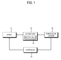
- FIG. 1 is a control block diagram of a computer system according to an exemplary embodiment of the present invention.
- a computer system includes a device 10; a battery unit 20 including battery cells 25; a temperature sensor 30; and a controller 40 to control the device 10, the battery unit 20, and the temperature sensor 30.
- the device 10 operates depending on a predetermined clock frequency and causes the computer system to perform various operations.
- the device 10 may include a central processing unit (CPU), a graphic chip, or the like, which includes an independent controller and operate and process data.
- the device 10 operates and processes data depending on a core clock or a similar clock.
- the speed of operating and processing data increases as the frequency of the core clock increases.
- an interior temperature of the device 10 increases as the speed of operating and processing data increases.
- the device 10 can independently control the clock frequency.
- the device 10 according to aspects of the present embodiment has a throttling function that changes the clock frequency to control the temperature and power.
- the battery unit 20 includes the battery cells 25 and supplies the device with power.
- a rechargeable auxiliary power source such as the battery unit 20, is necessary to a portable computer, such as a notebook computer, a personal digital assistant (PDA), etc.
- the battery cells 25 are connected in series or parallel and output power at various voltage levels. The more battery cells 25 the battery unit 20 includes, the greater the maximum consumable power that is output.
- the maximum consumable power refers to the maximum value within a range in which the battery can stably supply current to a load. As the speed of operating and processing data in the device 10 increases, the power consumption increases and a power supply which supplies the device 10 with the power, particularly, the battery unit 20 used as the auxiliary power source, increases in temperature.
- the battery unit 20 discharges power at a level greater than the maximum consumable power, the interior temperature of the battery unit 20 increases so rapidly that internal elements of the computer system, such as a logical fuse, a positive thermal coefficient (PTC) element, etc., are cut off one after another. Accordingly, it is beneficial to make the battery unit 20 output the power stably.
- PTC positive thermal coefficient
- the temperature sensor 30 senses the temperature of the battery unit 20, i.e., the battery cells 25, and outputs the sensed temperature to the controller 40.
- the temperature sensor 30 may output to the controller 40 a voltage level corresponding to the sensed temperature.
- the temperature sensor 30 may convert analog information about the sensed temperature into digital data and output the digital data corresponding to the sensed temperature to the controller 40.
- the controller 40 decreases the clock frequency of the device 10.
- the controller 40 may directly decrease the clock frequency of the device 10 or enable the throttling function of the device 10.
- the critical point is set to be lower than a temperature managed in the battery unit 20.
- a smarter battery which may be used as the battery unit 20, stops supplying power in order to protect itself when the interior temperature thereof reaches a certain temperature (about 80°C).
- the predetermined critical point may be set in a range from 45°C to 60°C.
- the controller 40 may decrease the clock frequency of the device 10 so as to stably supply the power and preliminarily protect the computer system.
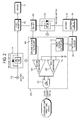
- FIG. 2 is a control block diagram of a computer system according to an exemplary embodiment of the present invention.
- the computer system in this embodiment includes an adapter 110, a battery 120, a first switch 131, a second switch 132, a DC/DC converter 140, a cell temperature sensor 200, a current sensor 300, and a controller 400 to control the foregoing and/or other elements.
- the controller 400 includes a first scaling factor unit 410, a second scaling factor unit 420, a first comparator 430, a second comparator 440, and an OR gate 450, and operates similar to the controller in the above-described embodiment associated with FIG.1 .
- the adapter 110 is used as a main power source to supply DC power converted from AC power to the device 10.
- the AC power input through the adapter 110 is converted into the DC power by the DC/DC converter 140, and the DC power is supplied to the system such as the device 10 or the like. Further, the adapter 110 supplies the battery 120 with power for charging the battery 120 via a predetermined path (not shown).
- the battery 120 includes a plurality of battery cells 125 and supplies the device 10 with auxiliary power. If the amount of current output from the battery 120 increases, the temperature of the battery cells 125 increases. The temperature of the battery cells 125 may increase by a malfunction or the like in addition to or instead of to the temperature increase in proportion to the increased current amount.
- the first switch 131 and the second switch 132 are provided as OR logic switches to supply the device 10 with the power from either of the adapter 110 or the battery 120. If the device 10 is supplied with the power from the adapter 110, the power from the battery 120 is cut off. However, if there is no power from the adapter 110, the battery 120 supplies the power to the device 10. As shown in FIG. 2 , the first switch 131 and the second switch 132 are provided as a field effect transistor (FET); however, the first switch 131 and the second switch 132 are not limited thereto. Additionally, the computer system may include a switch controller (not shown) to sense whether the power is supplied from the adapter 110 and transmits a control signal A to each of the first switch 131 and second switch 132.
- FET field effect transistor
- the computer system includes a cell temperature sensor 200 corresponding to the temperature sensor 30 of the above embodiment of FIG.1 .
- the current sensor 300 senses the amount of current output from the battery 120.
- the current sensor 300 according to this embodiment outputs a voltage level corresponding to the sensed current, but not limited thereto.
- the current sensor 300 may output a digital signal corresponding to the sensed current.
- the first scaling factor unit 410 scales the voltage level corresponding to the temperature sensed by the cell temperature sensor 200 as a dimension of a reference voltage level Vref
- the second scaling factor unit 420 scales the voltage level corresponding to the current sensed by the current sensor 300 as a dimension of the reference voltage level Vref.
- the first scaling factor unit 410 and the second scaling factor unit 420 may be provided as resistors.
- the same reference voltage level Vref is input to the first comparator 430 and the second comparator 440 as a reference.
- the voltage level input to each comparator 430 and 440 is scaled as a dimension of the reference voltage level Vref.
- the cell temperature sensor 200 and the current sensor 300 may output information, such as temperature and current, instead of the voltage level.
- the first scaling factor unit 410 and second scaling factor unit 420 may include a lookup table or the like to convert the temperature and the current into the dimension of the reference voltage.
- the lookup table includes information about the voltage level corresponding to the input temperature and the input current, and each of the first scaling factor unit 410 and second scaling factor unit 420 outputs a scaled value corresponding to the temperature and the current.
- the first comparator 430 compares a voltage level corresponding to temperature input through a non-inversion terminal with the reference voltage level input through an inversion terminal and outputs a predetermined signal through an output terminal if the voltage level corresponding to the sensed temperature is higher than the reference voltage level Vref.
- the second comparator 440 compares a voltage level corresponding to current input through the non-inversion terminal with the reference voltage level input through the inversion terminal and outputs a predetermined signal through an output terminal if the voltage level corresponding to the sensed current is higher than the reference voltage level Vref.
- the OR gate 450 is an element that implements a logical sum, of which a first input terminal connected to the output terminal of the first comparator 430 and a second input terminal connected to the output terminal of the second comparator 440.
- the OR gate 450 outputs a control signal if it receives the signal from either of the first comparator 430 or second comparator 440.
- the control signal output from the OR gate 450 is used as a clock control signal to enable the throttling function to lower the clock frequency of the device 10, such as the CPU or the graphic chip.
- the controller 400 outputs the clock control signal to enable the throttling function of the CPU or the graphic chip if either of the sensed current or the sensed temperature is beyond the critical point.
- FIG. 3 is a control block diagram of the device according to an exemplary embodiment of the present invention, which explains a throttling function of the device 10.
- the device 10 includes a silicon temperature sensor 11, an internal comparator 12, an auto mode/on-demand mode selector 13, and a thermal throttling circuit 14.
- the thermal throttling circuit 14 includes a thermal control circuit 15 and a throttling enabler 16.
- the internal comparator 12 compares the temperature input from the silicon temperature sensor 11 with an internal reference value Vref', and activates the thermal control circuit 15 when the sensed temperature is higher than the reference value Vref'.
- the auto mode/on-demand mode selector 13 operates depending on a basic input/output system (BIOS) to thereby switch operation of the thermal control circuit 15 between an auto mode and an on-demand mode.
- the thermal control circuit 15 operates when the auto mode/on-demand mode selector 13 outputs an enable signal.
- the enable signal output from the auto mode/on-demand mode selector 13 is a precondition for operating the thermal throttling circuit 14.
- the thermal control circuit 15 outputs an enable signal to the throttling enabler 16 if the clock control signal is output from the OR gate 45 (refer to FIG. 2 ), and controls the throttling enabler 16 to lower the clock frequency.
- the throttling enabler 16 changes the clock frequency and may be realized as a time-sharing divider that divides the clock frequency.
- FIG. 4 shows waveforms to explain a decrease in a clock frequency according to the exemplary embodiment of the present invention.
- (a) illustrates the core clock frequency of the CPU or the graphic chip, which typically ranges about from 1GHz to 2GHz; and (b) through (d) indicate that various divisions are applied to the core clock frequency. Specifically, (b), (c), and (d) indicate that divisions of 1/8, 1/2 and 7/8 are applied to the clock frequency having a certain period T, respectively. In the auto mode, the division of 1/2 is applied to the clock frequency (refer to (c)).
- (e) denotes the core clock frequency for two periods, which is divided like (c) and in which waveforms of (a) and (c)are synthesized. The clock frequency is enabled and output for a half of the certain period T, but disabled and not output for the other half. While the clock frequency is disabled, the CPU or the graphic chip temporarily becomes idle and thus power consumption decreases. Accordingly, the temperature of the battery 120 is decreased.
- FIGs. 5A through 5D are graphs showing a throttling effect according to an exemplary embodiment of the present invention.
- FIG. 5A shows a power consumption in the battery 120 and a temperature change of the battery cell 125 as time passes in the case that the throttling function is disabled. If a power of about 50W, on average, 53.4W is continuously consumed from the battery cells 125, the temperature of the battery cells 125 increases as time progresses.
- FIG. 5B is a graph showing the power consumption and the temperature change in the battery 120 in the case that the throttling function is enabled when the battery cells 125 are maintained at a temperature of about 45°C or more for approximately four minutes
- FIG. 5C is a graph showing the power consumption and the temperature change in the battery 120 in the case that the throttling function is enabled when the battery cells 125 are maintained at a temperature of about 50°C or more for approximately four minutes.
- FIGs. 5B and 5C if the throttling function is enabled, a temperature increase rate of the battery cells 125 is lowered, and the power consumption is rapidly decreased.
- an average power consumption was about 44.86W.
- an average power consumption was about 45.81W.
- the power consumption based on the enabled throttling function is less than that based on the disabled throttling function, so that the battery 120 can stably supply power and increase in lifespan.
- the throttling function is disabled if the battery cells 125 are maintained for a predetermined time at a temperature that is lower than the temperature causing the throttling function to be enabled.
- the clock frequency may increase if the battery cells 125 are maintained for about two minutes or more under the temperature of 40°C and below; and in the case shown in FIG. 5C , the clock frequency may increase if the battery cells 125 are maintained for about two minutes or more under the temperature of 45°C and below.
- the temperatures of the battery cells 125 for each of the above-described throttling situations are compared. As can be seen in FIG. 5D , when the throttling function is disabled, the temperature of the battery cells 125 continues to rise. When the throttling function is enabled at the temperatures of 45°C and 50°C, it can be seen that the temperatures of the battery cells 125 increases less than when the throttling function is disabled.
- FIG. 6 is a control flowchart that explains a control method of the computer system according to the second exemplary embodiment of the present invention.
- the controller 400 operates as follows: First, the cell temperature sensor 200 senses the temperature of the battery cells 125 at operation S10, and the current sensor 300 senses the current output from the battery 120 at operation S20.
- the voltage level corresponding to the sensed temperature and the voltage level corresponding to the sensed current are scaled as the dimension of the reference voltage level by the first scaling factor unit 410 and the second scaling factor unit 420, respectively.
- the first comparator 430 and the second comparator 440 determine whether the scaled voltage level corresponding to the temperature and the scaled voltage level corresponding to the current are beyond the reference voltage level, respectively.
- the controller 400 enables the thermal throttling circuit 14 provided in the device 10 at operation S70.
- the thermal control circuit 15 of the thermal throttling circuit 14 receives the clock control signal corresponding to the enable signal, and controls the throttling enabler 16 to divide the clock frequency at operation S80.
- the temperature control circuit 15 may control the throttling enabler 16 according to a logical sum between an activation signal from the internal comparator 12 and the clock control signal from the controller 400, but the temperature control circuit 15 is not limited thereto as such control is not necessary.
- the reference voltage levels Vref input to the first comparator 430 and the second comparator 440 may be different from each other.
- the reference voltage level Vref to be input to the first comparator 430 is set as a level corresponding to a critical temperature at which consumable power output from the battery 120 is not higher than the maximum consumable power.
- the reference voltage level Vref to be input to the second comparator 440 is set as a level corresponding to a critical current at which consumable power output from the battery 120 is not higher than the maximum consumable power. Accordingly, at least one of the first scaling factor unit 410 and the second scaling factor unit 420 may be not needed.
- the adapter 110, the switches 131 and 132, and the DC/DC converter 140 may be separated from the computer system and may be provided in a battery module.
- the clock control signal output from the controller 400 may be transmitted to the device 10 via a general system bus.
- other elements except the battery 120 may be provided in the computer system.
Landscapes
- Engineering & Computer Science (AREA)
- Theoretical Computer Science (AREA)
- Physics & Mathematics (AREA)
- General Engineering & Computer Science (AREA)
- General Physics & Mathematics (AREA)
- Human Computer Interaction (AREA)
- Power Sources (AREA)
Applications Claiming Priority (1)
| Application Number | Priority Date | Filing Date | Title |
|---|---|---|---|
| KR1020070076336A KR20090012479A (ko) | 2007-07-30 | 2007-07-30 | 배터리 모듈, 이를 포함하는 컴퓨터 시스템 및 그전원제어방법 |
Publications (2)
| Publication Number | Publication Date |
|---|---|
| EP2020630A2 true EP2020630A2 (fr) | 2009-02-04 |
| EP2020630A3 EP2020630A3 (fr) | 2012-11-07 |
Family
ID=39877906
Family Applications (1)
| Application Number | Title | Priority Date | Filing Date |
|---|---|---|---|
| EP08153748A Ceased EP2020630A3 (fr) | 2007-07-30 | 2008-03-31 | Module de batterie, système informatique doté de celui-ci et procédé de commande du système informatique |
Country Status (3)
| Country | Link |
|---|---|
| US (2) | US8433938B2 (fr) |
| EP (1) | EP2020630A3 (fr) |
| KR (1) | KR20090012479A (fr) |
Cited By (1)
| Publication number | Priority date | Publication date | Assignee | Title |
|---|---|---|---|---|
| EP3340009A1 (fr) * | 2016-12-23 | 2018-06-27 | Samsung Electronics Co., Ltd. | Dispositif électronique et procédé de commande de chaleur sur la base de la température d'une batterie dans un dispositif électronique |
Families Citing this family (14)
| Publication number | Priority date | Publication date | Assignee | Title |
|---|---|---|---|---|
| JP2010259254A (ja) | 2009-04-27 | 2010-11-11 | Panasonic Corp | 電流制御装置及び保護装置 |
| KR101230353B1 (ko) | 2010-01-28 | 2013-02-06 | 주식회사 엘지화학 | 전지 내부 저항을 이용한 저온 성능 개선 전지팩 시스템 |
| US8943335B2 (en) | 2010-12-22 | 2015-01-27 | Atmel Corporation | Battery management and protection system using a module in a sleepwalking mode to monitor operational characteristics of a battery |
| US9054528B2 (en) | 2010-12-22 | 2015-06-09 | Atmel Corporation | Event system and timekeeping for battery management and protection system |
| JP6189159B2 (ja) * | 2013-09-26 | 2017-08-30 | 株式会社東芝 | 電子機器、方法及びプログラム |
| US20180233430A1 (en) * | 2015-08-25 | 2018-08-16 | Nec Corporation | Processing device and processing system |
| KR102693757B1 (ko) * | 2016-08-19 | 2024-08-13 | 삼성전자주식회사 | 전자 장치와 이의 동작 방법 |
| US12079051B2 (en) * | 2018-11-28 | 2024-09-03 | Intel Corporation | Battery heat balancing apparatus and method during peak mode |
| US11126232B2 (en) * | 2018-11-28 | 2021-09-21 | Intel Corporation | Battery heat balancing during peak power mode |
| CN111552360B (zh) * | 2019-02-25 | 2022-04-19 | 研祥智能科技股份有限公司 | 工控机降温方法、装置、计算机设备及存储介质 |
| US11209879B2 (en) * | 2019-07-01 | 2021-12-28 | Dell Products L.P. | Method and apparatus for adjusting a workload to perform power management to extend battery cycle life |
| US12341163B2 (en) * | 2021-04-22 | 2025-06-24 | Apple Inc. | Battery temperature management |
| KR102474573B1 (ko) * | 2021-11-19 | 2022-12-06 | 주식회사 오토실리콘 | 싱글-셀 배터리 모니터링 회로, 싱글-셀 배터리 모니터링 반도체 집적회로 및 이를 구비한 배터리 유닛, 배터리 모듈 및 배터리 팩 |
| JP2023136721A (ja) * | 2022-03-17 | 2023-09-29 | 株式会社東芝 | 充電制御方法、充電制御装置及び電池搭載機器 |
Citations (5)
| Publication number | Priority date | Publication date | Assignee | Title |
|---|---|---|---|---|
| EP0926796A2 (fr) * | 1997-12-26 | 1999-06-30 | Hitachi, Ltd. | Dispositif de protection pour accumulateur |
| EP1225504A1 (fr) | 2001-01-18 | 2002-07-24 | Hewlett-Packard Company | Réduction de courant de décharge de batterie par étranglement de puissance CPU |
| US20020099962A1 (en) * | 2001-01-25 | 2002-07-25 | Kabushiki Kaisha Toshiba | Information processing apparatus suitably controlling activation and stoppage of power consumption reducing function and power consumption controlling method of the apparatus |
| EP1471593A1 (fr) | 2002-01-29 | 2004-10-27 | Sony Corporation | Regulateur d'alimentation, procede de regulation d'alimentation, unite de traitement d'informations et programme de regulation d'alimentation |
| US20040236969A1 (en) | 2003-05-21 | 2004-11-25 | Lippert Kurt J. | Method and system for dynamically adjusting power consumption of an information handling system |
Family Cites Families (28)
| Publication number | Priority date | Publication date | Assignee | Title |
|---|---|---|---|---|
| US5563496A (en) * | 1990-12-11 | 1996-10-08 | Span, Inc. | Battery monitoring and charging control unit |
| US5230074A (en) * | 1991-01-25 | 1993-07-20 | International Business Machines Corporation | Battery operated computer power management system |
| CN1119054A (zh) * | 1993-03-05 | 1996-03-20 | 摩托罗拉公司 | 具有存储器的存储充电过程的电池 |
| US5581206A (en) * | 1995-07-28 | 1996-12-03 | Micron Quantum Devices, Inc. | Power level detection circuit |
| US6448821B1 (en) * | 2000-02-25 | 2002-09-10 | National Semiconductor Corporation | Comparator circuit for comparing differential input signal with reference signal and method |
| US6531848B1 (en) * | 2000-05-26 | 2003-03-11 | Arris International, Inc. | Battery voltage regulation circuit |
| JP4566392B2 (ja) * | 2000-11-16 | 2010-10-20 | レノボ シンガポール プライヴェート リミテッド | 温度制御に伴うアクションレベルを決定する電池、電池パック、コンピュータ装置、電気機器、および電池の温度制御方法 |
| KR100867589B1 (ko) | 2002-04-17 | 2008-11-10 | 엘지전자 주식회사 | 배터리 잔량에 따른 휴대용 기기의 열 관리방법 |
| TWI262380B (en) * | 2002-04-25 | 2006-09-21 | Quanta Comp Inc | Dynamic adjustment method for power consumption of computer system |
| US20040070371A1 (en) * | 2002-10-11 | 2004-04-15 | Compaq Information Technologies Group, L.P. | Power management of a battery operated computer system based on battery status |
| TW200416522A (en) * | 2003-02-25 | 2004-09-01 | Asustek Comp Inc | Portable computer carrying desktop computer processor and power management method thereof |
| TWI280475B (en) | 2003-06-16 | 2007-05-01 | Wistron Corp | Method of controlling operation mode of a computer system |
| US7406623B2 (en) * | 2003-09-29 | 2008-07-29 | Hitachi Computer Peripherals Co., Ltd. | DC backup power supply system and disk array using same |
| US7171577B2 (en) * | 2003-10-06 | 2007-01-30 | Texas Instruments Incorporated | Methods and apparatus for a system clock divider |
| US7057372B2 (en) * | 2003-10-17 | 2006-06-06 | Research In Motion Limited | Battery management system and method |
| US7233127B2 (en) * | 2003-10-17 | 2007-06-19 | Research In Motion Limited | Battery management system and method |
| US7386737B2 (en) * | 2004-11-02 | 2008-06-10 | Intel Corporation | Method and apparatus to control temperature of processor |
| JP2006145285A (ja) * | 2004-11-17 | 2006-06-08 | Ricoh Co Ltd | 電池残量検出装置 |
| KR200382190Y1 (ko) | 2004-12-02 | 2005-04-19 | 신영지 | 상처 보호용 밴드 |
| TWI301568B (en) * | 2005-05-11 | 2008-10-01 | Quanta Comp Inc | Temperature control system |
| CN100412755C (zh) * | 2005-09-02 | 2008-08-20 | 鸿富锦精密工业(深圳)有限公司 | 中央处理器频率即时调整电路 |
| JP4327143B2 (ja) * | 2005-09-30 | 2009-09-09 | パナソニックEvエナジー株式会社 | 二次電池用の制御装置及び二次電池の出力制御方法及び二次電池の出力制御実行プログラム |
| US7443176B2 (en) * | 2005-11-22 | 2008-10-28 | Stmicroelectronics, Inc. | Test mode and test method for a temperature tamper detection circuit |
| US7514904B2 (en) * | 2005-12-20 | 2009-04-07 | Caterpillar Inc. | System and method for determining battery temperature |
| EP2089788A4 (fr) * | 2006-10-27 | 2012-01-25 | Ecosol Solar Technologies Ltd | Dispositif d'alimentation-mémoire en combinaison |
| US8001400B2 (en) * | 2006-12-01 | 2011-08-16 | Apple Inc. | Power consumption management for functional preservation in a battery-powered electronic device |
| US7737662B2 (en) * | 2006-12-26 | 2010-06-15 | O2Micro International Ltd. | Power management circuit for battery pack |
| US20080158220A1 (en) * | 2007-01-03 | 2008-07-03 | Himax Technologies Limited | Power-on-reset circuit and method therefor |
-
2007
- 2007-07-30 KR KR1020070076336A patent/KR20090012479A/ko not_active Ceased
-
2008
- 2008-03-31 EP EP08153748A patent/EP2020630A3/fr not_active Ceased
- 2008-07-22 US US12/177,200 patent/US8433938B2/en active Active
-
2013
- 2013-04-02 US US13/855,380 patent/US9405352B2/en active Active
Patent Citations (5)
| Publication number | Priority date | Publication date | Assignee | Title |
|---|---|---|---|---|
| EP0926796A2 (fr) * | 1997-12-26 | 1999-06-30 | Hitachi, Ltd. | Dispositif de protection pour accumulateur |
| EP1225504A1 (fr) | 2001-01-18 | 2002-07-24 | Hewlett-Packard Company | Réduction de courant de décharge de batterie par étranglement de puissance CPU |
| US20020099962A1 (en) * | 2001-01-25 | 2002-07-25 | Kabushiki Kaisha Toshiba | Information processing apparatus suitably controlling activation and stoppage of power consumption reducing function and power consumption controlling method of the apparatus |
| EP1471593A1 (fr) | 2002-01-29 | 2004-10-27 | Sony Corporation | Regulateur d'alimentation, procede de regulation d'alimentation, unite de traitement d'informations et programme de regulation d'alimentation |
| US20040236969A1 (en) | 2003-05-21 | 2004-11-25 | Lippert Kurt J. | Method and system for dynamically adjusting power consumption of an information handling system |
Cited By (2)
| Publication number | Priority date | Publication date | Assignee | Title |
|---|---|---|---|---|
| EP3340009A1 (fr) * | 2016-12-23 | 2018-06-27 | Samsung Electronics Co., Ltd. | Dispositif électronique et procédé de commande de chaleur sur la base de la température d'une batterie dans un dispositif électronique |
| US10698461B2 (en) | 2016-12-23 | 2020-06-30 | Samsung Electronics Co., Ltd. | Electronic device and heat control method based on temperature of battery in electronic device |
Also Published As
| Publication number | Publication date |
|---|---|
| US8433938B2 (en) | 2013-04-30 |
| KR20090012479A (ko) | 2009-02-04 |
| EP2020630A3 (fr) | 2012-11-07 |
| US20130227322A1 (en) | 2013-08-29 |
| US20090037754A1 (en) | 2009-02-05 |
| US9405352B2 (en) | 2016-08-02 |
Similar Documents
| Publication | Publication Date | Title |
|---|---|---|
| EP2020630A2 (fr) | Module de batterie, système informatique doté de celui-ci et procédé de commande du système informatique | |
| US9430008B2 (en) | Apparatus and method for optimizing use of NVDC chargers | |
| EP1856593B1 (fr) | Systemes et procedes permettant de reguler la consommation d'electricite dans un systeme informatique | |
| US7608942B2 (en) | Power management system | |
| US7781908B2 (en) | Output power port management control | |
| US8350408B2 (en) | Power management circuit | |
| EP2485117A2 (fr) | Procédé et appareil pour régler la tension et la fréquence afin de minimiser la dissipation de puissance dans un système multiprocesseur | |
| US8232762B2 (en) | Computer and battery charging method thereof | |
| EP1081838B1 (fr) | Méthode et dispositif de contrôle de puissance, et alimentation de puissance | |
| KR20080011088A (ko) | 정전압 전원 회로 | |
| JP2018517955A (ja) | 高速のスタートアップのスタンドバイモードを有するクロック生成回路 | |
| EP4016789A1 (fr) | Dispositif de gestion de batterie | |
| US20150089260A1 (en) | Electronic Apparatus, Method, and Storage Medium | |
| KR20150085642A (ko) | 전원 공급 장치, 이를 포함하는 전자 장치 및 전원 공급 방법 | |
| KR101557921B1 (ko) | 적응형 전압 스케일링(avs)을 수행하기 위한 방법 및 avs를 수행하도록 구성되는 집적 회로 | |
| US7701178B2 (en) | Charge control that keeps constant input voltage supplied to battery pack | |
| US7012408B2 (en) | Electronic apparatus capable of effectively using power of an AC/DC adaptor | |
| US20240396350A1 (en) | Power supply circuit | |
| US6597153B1 (en) | Fast transient charging circuit | |
| US20070150765A1 (en) | Information processing apparatus having electronic device whose operating speed is controlled, and method of controlling the operating speed of the electronic device | |
| KR100534110B1 (ko) | Usb전원공급장치 | |
| JP2003195988A (ja) | 消費電力管理装置およびその方法 | |
| CN116593022A (zh) | 温度感测装置 | |
| US6137279A (en) | Adjustable power control module and applications thereof | |
| US20070094521A1 (en) | Current-sensing control system for a microprocessor |
Legal Events
| Date | Code | Title | Description |
|---|---|---|---|
| PUAI | Public reference made under article 153(3) epc to a published international application that has entered the european phase |
Free format text: ORIGINAL CODE: 0009012 |
|
| AK | Designated contracting states |
Kind code of ref document: A2 Designated state(s): AT BE BG CH CY CZ DE DK EE ES FI FR GB GR HR HU IE IS IT LI LT LU LV MC MT NL NO PL PT RO SE SI SK TR |
|
| AX | Request for extension of the european patent |
Extension state: AL BA MK RS |
|
| RAP1 | Party data changed (applicant data changed or rights of an application transferred) |
Owner name: SAMSUNG ELECTRONICS CO., LTD. |
|
| PUAL | Search report despatched |
Free format text: ORIGINAL CODE: 0009013 |
|
| AK | Designated contracting states |
Kind code of ref document: A3 Designated state(s): AT BE BG CH CY CZ DE DK EE ES FI FR GB GR HR HU IE IS IT LI LT LU LV MC MT NL NO PL PT RO SE SI SK TR |
|
| AX | Request for extension of the european patent |
Extension state: AL BA MK RS |
|
| RIC1 | Information provided on ipc code assigned before grant |
Ipc: G06F 1/32 20060101ALN20121001BHEP Ipc: G06F 1/20 20060101AFI20121001BHEP |
|
| 17P | Request for examination filed |
Effective date: 20130507 |
|
| AKX | Designation fees paid |
Designated state(s): DE FR GB |
|
| 17Q | First examination report despatched |
Effective date: 20130614 |
|
| STAA | Information on the status of an ep patent application or granted ep patent |
Free format text: STATUS: THE APPLICATION HAS BEEN REFUSED |
|
| 18R | Application refused |
Effective date: 20160312 |