EP2020664B1 - Handgriff für einen gekapselten Leistungsschalter und Leistungsschaltereinheit mit derartigem Handgriff - Google Patents
Handgriff für einen gekapselten Leistungsschalter und Leistungsschaltereinheit mit derartigem Handgriff Download PDFInfo
- Publication number
- EP2020664B1 EP2020664B1 EP07425489A EP07425489A EP2020664B1 EP 2020664 B1 EP2020664 B1 EP 2020664B1 EP 07425489 A EP07425489 A EP 07425489A EP 07425489 A EP07425489 A EP 07425489A EP 2020664 B1 EP2020664 B1 EP 2020664B1
- Authority
- EP
- European Patent Office
- Prior art keywords
- handgrip
- circuit breaker
- box
- piece
- type casing
- Prior art date
- Legal status (The legal status is an assumption and is not a legal conclusion. Google has not performed a legal analysis and makes no representation as to the accuracy of the status listed.)
- Active
Links
Images

Classifications
-
- H—ELECTRICITY
- H01—ELECTRIC ELEMENTS
- H01H—ELECTRIC SWITCHES; RELAYS; SELECTORS; EMERGENCY PROTECTIVE DEVICES
- H01H9/00—Details of switching devices, not covered by groups H01H1/00 - H01H7/00
- H01H9/02—Bases, casings, or covers
- H01H9/0264—Protective covers for terminals
-
- H—ELECTRICITY
- H01—ELECTRIC ELEMENTS
- H01H—ELECTRIC SWITCHES; RELAYS; SELECTORS; EMERGENCY PROTECTIVE DEVICES
- H01H71/00—Details of the protective switches or relays covered by groups H01H73/00 - H01H83/00
- H01H71/02—Housings; Casings; Bases; Mountings
- H01H71/0264—Mountings or coverplates for complete assembled circuit breakers, e.g. snap mounting in panel
-
- H—ELECTRICITY
- H01—ELECTRIC ELEMENTS
- H01H—ELECTRIC SWITCHES; RELAYS; SELECTORS; EMERGENCY PROTECTIVE DEVICES
- H01H73/00—Protective overload circuit-breaking switches in which excess current opens the contacts by automatic release of mechanical energy stored by previous operation of a hand reset mechanism
- H01H73/02—Details
- H01H73/06—Housings; Casings; Bases; Mountings
- H01H73/08—Plug-in housings
Definitions
- the present invention relates to the technical sector of electrical circuit breakers and in particular it relates to a handgrip for an electrical molded case circuit breaker.
- Document EP 1 739 704 discloses a device according to the preamble of claim 1.
- the object of the present invention is to provide a handgrip that can be associated to a molded case circuit breaker which, besides facilitating manual grasping of the breaker, is also such as to prevent dangerous access to the electricalally conductive and exposed parts of the circuit breaker.
- a further object of the present invention is a circuit breaker unit as defined in the attached claim 13.
- circuit breaker unit comprising a handgrip according to a preferred embodiment of the present invention.
- the circuit breaker unit comprises a molded case circuit breaker 1, for example a three-pole circuit breaker with thermal and magnetic protection.
- a molded case circuit breaker as opposed to a circuit breaker of the so-called "air" type, has a box-type casing 2 generally parallelepiped and made of insulating material, which acts as support for the mechanisms inside the circuit breaker.
- molded case circuit breakers are generally used in the industrial automation and advanced tertiary sectors for interrupting currents for example with values up to 1500 A.
- the front face 3 of the box-type casing 2 having a substantially quadrangular shape, is provided with an opening through which a rotating lever 4 passes for controlling the circuit breaker 1.
- a first group of three terminals for electrical connection 6 is provided, for connecting the circuit breaker 1 to an electrical circuit outside the breaker 1, for example to an electrical circuit upstream of the breaker 1.
- a similar group of electrical connection terminals 8 is provided on one lower horizontal face 7 of the box-type casing 2, for connecting the breaker 1 to an electrical circuit outside the breaker 1, for example downstream of the breaker 1.
- the electrical terminals 6 are at least partially housed in respective recesses 9 provided in the box-type casing 2 near the upper face 5.
- said recesses 9 house a substantially plate-shaped end portion of the electrical terminals 6.
- the electrical terminals 6 have a conductive bar perpendicular to the plate-shaped end portion and have an opposite rounded end portion, such as to be engaged with a corresponding connection terminal provided in a control panel or insertion board.
- the conductive bar of the terminals 6 juts out from the horizontal face 5 projecting towards the rear face 34 of the box-type casing 2.
- the connection terminals 6 could be common screw terminals housed in the recesses 9 and such as to be connected to cable conductors for connection of the breaker 1 to an external circuit.
- Each housing recess 9 is provided with an open end portion 10 on the front face 3 of the box-type casing 2.
- connection terminals 8 Similar housing recesses, not visible in the drawings, are provided in the box-type casing 2 near the lower horizontal face 7 for housing, at least partially, the other electrical terminals 8 of the breaker 1. Said recesses are also provided with an open end portion 11 on the front face 3 of the box-type casing 2 of the breaker 1. As far as the connection terminals 8 are concerned, the same applies as that described for the connection terminals 6.
- the housing recesses 9 have one open side on the upper horizontal face 5 of the box-type casing 2. Similar open sides are provided in the recesses, not visible, arranged on the lower horizontal face 7.
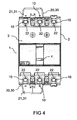
- a handgrip 20, 30 is associated to the breaker 1, conveniently made of electrically insulating material and comprising a gripping organ 21, 31 intended to project from the main casing 2 of the associated breaker 1, to facilitate manual grasping of the breaker 1.
- the handgrip 20, 30 comprises an array of protective elements 22 in insulating material.
- Each of said protective elements 22 is such as to be engaged with a corresponding recess 9 of the box-type casing 2 so as to prevent dangerous access to the connection terminal 6 through the open end portion 10 of the recess 9.
- the protective elements 22 are made in the shape of bars having a substantially disc-shaped end portion.
- each protective element 22 can be engaged with the respective recess 9 by axially crossing through the open end portion 10 of said recess 9, as indicate by the arrow IV in figure 1 .
- Axial direction means a direction perpendicular to the front face 3 of the box-type casing 2 of the breaker 1.
- the handgrip 20, 30 comprises a bar 23 at the base of the gripping organ 21.
- Said bar 23 extends transversally compared to the axial direction of the recesses 9 and the array of protective elements 22 juts out from the bar 23 on the opposite side from the gripping organ 21, 31.
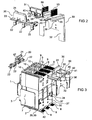
- the handgrip is essentially made of two distinct and combinable pieces 20, 30, shown disassembled in said figure.
- the handgrip comprises a front piece 20 comprising the array of protective elements 22 and a rear piece 30 essentially "L" shaped and including:
- the first part 32 of the rear piece of the handgrip 30 is, for example, provided with one or more openings 36 to permit fixing, by means of screws, the rear piece 30 to the rear face 34 of the box-type casing 2.
- the second part 35 of the rear piece of the handgrip 30 comprises guided coupling means 38, for coupling the rear piece 30 to the horizontal face 5 of the box-type casing 3, interacting with combined guided coupling means 39 provided in the box-type casing 2 on the horizontal face 5.
- the guided coupling means 38 comprise at least one cursor 38 which slides into a respective counter-shaped slot 39 provided in the box-type casing 2 ( figure 1 ).
- the cursor 38 is preferably made with a dovetail section so as to firmly engage the first part 35 of the rear piece of the handgrip 30 to the horizontal face 5.
- the arrow V in figure 1 indicates the direction and insertion direction of the cursors 38 into the slots 39.
- the second part 35 of the rear handgrip piece 30 is such as to be juxtaposed to the horizontal face 5 in order to prevent any possible access to the terminals 6 from the side of the horizontal face 5.
- the second part 35 of the rear handgrip piece 30 preferably includes a plurality of grooves 40, each defining a slot with insulating walls intended to receive a respective terminal bar 6 or, alternatively, a terminal cable, coming out from the horizontal face 5. More preferably, the grooves 40 terminate with an end portion 41 facing the rear face of the box-type casing 2 which is open so it can be crossed by a terminal bar 6, or terminal cable.
- end portion 41 is intended to be crossed by a terminal bar 6, it is possible to provide an insulating and projecting collar 42 such as to be received in an opening which accesses the terminal into which the terminal 6 is to be inserted.
- end portions of terminals 6 must be provided which project beyond said collar 52, so that the electrical connection can be made between the terminal 6 and a corresponding terminal, provided for example in an insertion board.
- the gripping organ 21, 31 is essentially shaped like a trapezoidal plate and comprises two juxtaposed plates provided in the front piece of the handgrip 20 and in the rear piece of the handgrip 30 respectively.
- the two plates form a single plate 21, 31 projecting from the casing 2 of the circuit breaker 1 and such as to facilitate manual grasping of the breaker.
- further removable fixing means can optionally be provided in order to ensure safe coupling of the two pieces 20, 30 of the handgrip, such as screws, bolts and similar.
- the handgrip 20, 30 can further be provided with centering and guiding means, for example a pair of projecting fins 50, such as to facilitate the insertion of a circuit breaker into an insertion board provided with combined insertion and guiding means, for example in the form of guiding grooves, not shown in the drawings, and such as to interact with a respective fin 50.
- centering and guiding means for example a pair of projecting fins 50, such as to facilitate the insertion of a circuit breaker into an insertion board provided with combined insertion and guiding means, for example in the form of guiding grooves, not shown in the drawings, and such as to interact with a respective fin 50.
- a handgrip according to the present invention makes it possible to entirely satisfy the above-described requirements with reference to the prior art.
- a handgrip according to the present invention facilitates and makes safe the operations of installation/removal of the circuit breaker, also preventing access to the exposed conductive parts of the circuit breaker when the breaker is installed and fed.
Landscapes
- Breakers (AREA)
- Switch Cases, Indication, And Locking (AREA)
Claims (13)
- Handgriff (20, 30), der mit einem elektrischen Formgehäuse-Stromtrennschalter (1) verbunden werden kann, wobei der Trennschalter zumindest eine erste Einheit von elektrischen Verbindungsanschlüssen (6) und ein mit zumindest einer ersten Vielzahl von Aussparungen (9) zum Aufnehmen der elektrischen Anschlüsse (6) versehenes behälterförmiges Gehäuse (2) umfasst, wobei jede Aussparung mit einem offenen Endabschnitt (10) an einer vorderen Fläche (3) des behälterförmigen Gehäuses (2) versehen ist, wobei der Handgriff (20, 30) ein Greifmittel (21, 31) umfasst, das vom Hauptgehäuse (2) hervorsteht, um ein manuelles Greifen des Trennschalters (1) zu erleichtern,
dadurch gekennzeichnet, dass
der Handgriff (20, 30) weiter eine Anordnung von Schutzelementen (22) in einem Isoliermaterial aufweist, wobei jedes derart mit einer entsprechenden Aussparung (9) in Eingriff ist, um einen Zugang zum Verbindungsanschluss (6) durch den offenen Endabschnitt (10) zu verhindern. - Handgriff (20, 30) gemäß Anspruch 1, bei dem jedes Schutzelement (22) axial mit dem offenen Endabschnitt (10) einer entsprechenden Aussparung (9) in Eingriff gebracht werden kann.
- Handgriff (20, 30) gemäß Anspruch 1, wobei der Handgriff eine Schiene (23) an der Basis des Greifmittels (21, 31) aufweist, wobei sich die Schiene quer verglichen mit der Axialrichtung der Gehäuseaussparung (9) erstreckt, wobei die Anordnung der Schutzelemente (22) von der Seite gegenüber dem Greifmittel (21, 31) von der Schiene (23) hervorsteht.
- Handgriff (20, 30) gemäß Anspruch 3, bei dem die Schutzelemente einen von der Schiene (23) entfernt gelegenen Endabschnitt umfassen, der im Wesentlichen scheibenförmig ist.
- Handgriff (20, 30) gemäß einem der vorangegangenen Ansprüche, bei dem der Handgriff im Wesentlichen als zwei eigene und kombinierbare Stücken (20, 30) gefertigt ist, von denen ein vorderes Handgriffstück (20) die Anordnung der Schutzelemente (22) umfasst, und ein hinteres Handgriffstück (30) im Wesentlichen L-förmig ist und aufweist:einen ersten Teil (32), der im Wesentlichen plattenförmig ist, und neben eine hintere Fläche (34) des behälterförmigen Gehäuses (2) gebracht werden soll,einen zweiten Teil (35), der im rechten Winkel zum ersten Teil (32) befindlich ist, und der eine mit dem ersten Teil (32) verbundene erste Endsektion (32) und einen gegenüberliegenden Endabschnitt aufweist, der mit dem vorderen Handgriffstück (20) interagieren soll.
- Handgriff (20, 30) gemäß Anspruch 5, bei dem die Gehäuseaussparung (9) an einer Seitenfläche (5, 7) des behälterförmigen Gehäuses (2) eine offene Seite aufweist, und bei dem die Verbindungsanschlüsse (6) Schienen oder Kabel umfassen, die außerhalb des behälterförmigen Gehäuses (2) hervorstehen, und die sich parallel zur Seitenfläche (5, 7) in Richtung der hinteren Fläche (34) erstrecken, wobei der zweite Teil (35) des hinteren Handgriffstücks (30) derart ist, dass er neben die Seitenfläche (5) gebracht wird, um einen Zugang zu den Schienen oder Kabeln von der Seitenfläche (5) zu verhindern.
- Handgriff (20, 30) gemäß Anspruch 6, bei dem der zweite Teil (35) des hinteren Handgriffstücks (30) eine Vielzahl von Nuten (40) aufweist, von denen jede einen Schlitz definiert, um eine/ ein entsprechende/s, hervorstehende/s Schiene oder Kabel zu empfangen.
- Handgriff (20, 30) gemäß Anspruch 7, bei dem die Nuten mit einem zur hinteren Fläche des Stromtrennschalters weisenden offenen Endabschnitt derart enden, dass das hintere Handgriffstück (32) durch die Schienen oder Kabel gekreuzt werden kann.
- Handgriff (20, 30) gemäß einem der vorangegangenen Ansprüche 5 bis 8, bei dem das Greifmittel zwei nebeneinander befindliche Platten (21, 31) umfasst, die entsprechend im vorderen Handgriffstück (20) und im hinteren Handgriffstück (30) vorgesehen sind.
- Handgriff (20, 30) gemäß einem der vorangegangenen Ansprüche 6 bis 9, bei dem der zweite Teil (35) des hinteren Handgriffstücks (30) ein geführtes Kopplungsmittel (38) zum Koppeln des hinteren Stücks (30) mit der Seitenfläche (5) des behälterförmigen Gehäuses (2) umfasst, die mit einem in dem behälterförmigen Gehäuse (2) an der Seitenfläche (5) vorgesehenen, kombiniert-geführten Koppelmittel (39) interagieren können.
- Handgriff (20, 30) gemäß Anspruch 10, bei dem das geführte Koppelmittel zumindest einen Positionsanzeiger (38) mit schwalbenschwanzförmiger Sektion umfasst.
- Handgriff (20, 30) gemäß einem der vorangegangenen Ansprüche, wobei der Handgriff weiter ein geführtes Zentriermittel (50) umfasst, um das Einführen des Stromtrennschalters (1) in eine mit einem kombinierten Einführ- und Führungsmittel versehene Einführplatte zu erleichtern.
- Stromtrennschaltereinheit (1, 20, 30), umfassend einen Formgehäuse-Stromtrennschalter (1) und zumindest einen Handgriff (20, 30) gemäß einem der vorangegangenen Ansprüche.
Priority Applications (5)
| Application Number | Priority Date | Filing Date | Title |
|---|---|---|---|
| DE602007005247T DE602007005247D1 (de) | 2007-07-31 | 2007-07-31 | Handgriff für einen gekapselten Leistungsschalter und Leistungsschaltereinheit mit derartigem Handgriff |
| EP07425489A EP2020664B1 (de) | 2007-07-31 | 2007-07-31 | Handgriff für einen gekapselten Leistungsschalter und Leistungsschaltereinheit mit derartigem Handgriff |
| AT07425489T ATE460740T1 (de) | 2007-07-31 | 2007-07-31 | Handgriff für einen gekapselten leistungsschalter und leistungsschaltereinheit mit derartigem handgriff |
| ES07425489T ES2342212T3 (es) | 2007-07-31 | 2007-07-31 | Asa para disyuntor de circuito electrico en carcasa moldeada y unidad de disyuntor de circuito que comprende dicho asa. |
| PL07425489T PL2020664T3 (pl) | 2007-07-31 | 2007-07-31 | Ręczny uchwyt do wyłącznika elektrycznego z formowaną obudową i wyłącznik elektryczny zawierający wspomniany ręczny uchwyt |
Applications Claiming Priority (1)
| Application Number | Priority Date | Filing Date | Title |
|---|---|---|---|
| EP07425489A EP2020664B1 (de) | 2007-07-31 | 2007-07-31 | Handgriff für einen gekapselten Leistungsschalter und Leistungsschaltereinheit mit derartigem Handgriff |
Publications (2)
| Publication Number | Publication Date |
|---|---|
| EP2020664A1 EP2020664A1 (de) | 2009-02-04 |
| EP2020664B1 true EP2020664B1 (de) | 2010-03-10 |
Family
ID=38697518
Family Applications (1)
| Application Number | Title | Priority Date | Filing Date |
|---|---|---|---|
| EP07425489A Active EP2020664B1 (de) | 2007-07-31 | 2007-07-31 | Handgriff für einen gekapselten Leistungsschalter und Leistungsschaltereinheit mit derartigem Handgriff |
Country Status (5)
| Country | Link |
|---|---|
| EP (1) | EP2020664B1 (de) |
| AT (1) | ATE460740T1 (de) |
| DE (1) | DE602007005247D1 (de) |
| ES (1) | ES2342212T3 (de) |
| PL (1) | PL2020664T3 (de) |
Families Citing this family (1)
| Publication number | Priority date | Publication date | Assignee | Title |
|---|---|---|---|---|
| USD904987S1 (en) * | 2018-10-19 | 2020-12-15 | Lsis Co., Ltd. | Molded case circuit breaker |
Family Cites Families (2)
| Publication number | Priority date | Publication date | Assignee | Title |
|---|---|---|---|---|
| US6541722B1 (en) * | 2001-10-19 | 2003-04-01 | Eaton Corporation | Finger barrier for electric power switches and electric power switch incorporating the same |
| US7403088B2 (en) * | 2005-06-29 | 2008-07-22 | Eaton Corporation | Handle apparatus and electrical switching apparartus employing the same |
-
2007
- 2007-07-31 ES ES07425489T patent/ES2342212T3/es active Active
- 2007-07-31 PL PL07425489T patent/PL2020664T3/pl unknown
- 2007-07-31 DE DE602007005247T patent/DE602007005247D1/de not_active Expired - Fee Related
- 2007-07-31 EP EP07425489A patent/EP2020664B1/de active Active
- 2007-07-31 AT AT07425489T patent/ATE460740T1/de not_active IP Right Cessation
Also Published As
| Publication number | Publication date |
|---|---|
| DE602007005247D1 (de) | 2010-04-22 |
| PL2020664T3 (pl) | 2010-07-30 |
| ATE460740T1 (de) | 2010-03-15 |
| ES2342212T3 (es) | 2010-07-02 |
| EP2020664A1 (de) | 2009-02-04 |
Similar Documents
| Publication | Publication Date | Title |
|---|---|---|
| CA2124007C (en) | Panelboard interior assembly and method of making same | |
| US9490086B2 (en) | Molded case circuit breaker accessory wiring improvement | |
| AU2022279544B2 (en) | Universal tap-off box | |
| CN101540247B (zh) | 用于低压开关设备的适配器装置 | |
| US5204798A (en) | Metering accessory for molded case circuit breakers | |
| CA2039033C (en) | Adapter providing unitary mounting capability for standard circuit breaker | |
| US4668035A (en) | Distribution system and column for electric switching apparatus | |
| EP1975966B1 (de) | Elektrisches Schaltgerät und Verriegelung der Phasentrennung dafür | |
| US6137068A (en) | Combined handle-guard and grip for plug-in circuit breakers | |
| US6424519B2 (en) | Plug-in draw out unit | |
| EP1739704B1 (de) | Griffanordnung und und damit versehene elektrische Schaltvorrichtung | |
| US6323448B1 (en) | Circuit breaker stab contact assembly with spring clip | |
| EP3227896B1 (de) | Flache, schmelzbare trennschaltervorrichtung | |
| EP2020664A1 (de) | Handgriff für einen gekapselten Leistungsschalter und Leistungsschaltereinheit mit derartigem Handgriff | |
| CA2103312C (en) | Protective cover for electrical terminals and method of using same | |
| US7173811B2 (en) | Power circuit breakers with offset vertical quick disconnect adapters to allow plugging onto a line and a load bus in different planes | |
| GB2230901A (en) | Electrical distribution board equipped with disconnectors | |
| CN111048370B (zh) | 一种断路器用高分段灭弧室 | |
| US4781627A (en) | Bus bar stab and insulator assembly | |
| CN101577195B (zh) | 模块化电装置 | |
| EP2269204B1 (de) | Modulare elektrische vorrichtung mit schutzmitteln zur verhinderung von elektrischen bogen | |
| CA2901430C (en) | Handle tie apparatus for g-frame 1 pole breakers | |
| ITRM20070417A1 (it) | Maniglia di presa per interruttore elettrico scatolato e gruppo interruttore comprendente tale maniglia | |
| US20060061439A1 (en) | Circuit breaker with a moveable plug contact | |
| US20210050715A1 (en) | Wire organization apparatus and method |
Legal Events
| Date | Code | Title | Description |
|---|---|---|---|
| PUAI | Public reference made under article 153(3) epc to a published international application that has entered the european phase |
Free format text: ORIGINAL CODE: 0009012 |
|
| AK | Designated contracting states |
Kind code of ref document: A1 Designated state(s): AT BE BG CH CY CZ DE DK EE ES FI FR GB GR HU IE IS IT LI LT LU LV MC MT NL PL PT RO SE SI SK TR |
|
| AX | Request for extension of the european patent |
Extension state: AL BA HR MK RS |
|
| 17P | Request for examination filed |
Effective date: 20090212 |
|
| AKX | Designation fees paid |
Designated state(s): AT BE BG CH CY CZ DE DK EE ES FI FR GB GR HU IE IS IT LI LT LU LV MC MT NL PL PT RO SE SI SK TR |
|
| GRAP | Despatch of communication of intention to grant a patent |
Free format text: ORIGINAL CODE: EPIDOSNIGR1 |
|
| GRAS | Grant fee paid |
Free format text: ORIGINAL CODE: EPIDOSNIGR3 |
|
| GRAA | (expected) grant |
Free format text: ORIGINAL CODE: 0009210 |
|
| AK | Designated contracting states |
Kind code of ref document: B1 Designated state(s): AT BE BG CH CY CZ DE DK EE ES FI FR GB GR HU IE IS IT LI LT LU LV MC MT NL PL PT RO SE SI SK TR |
|
| REG | Reference to a national code |
Ref country code: GB Ref legal event code: FG4D |
|
| REG | Reference to a national code |
Ref country code: CH Ref legal event code: EP |
|
| REG | Reference to a national code |
Ref country code: IE Ref legal event code: FG4D |
|
| REF | Corresponds to: |
Ref document number: 602007005247 Country of ref document: DE Date of ref document: 20100422 Kind code of ref document: P |
|
| REG | Reference to a national code |
Ref country code: NL Ref legal event code: VDEP Effective date: 20100310 |
|
| REG | Reference to a national code |
Ref country code: ES Ref legal event code: FG2A Ref document number: 2342212 Country of ref document: ES Kind code of ref document: T3 |
|
| PG25 | Lapsed in a contracting state [announced via postgrant information from national office to epo] |
Ref country code: LT Free format text: LAPSE BECAUSE OF FAILURE TO SUBMIT A TRANSLATION OF THE DESCRIPTION OR TO PAY THE FEE WITHIN THE PRESCRIBED TIME-LIMIT Effective date: 20100310 |
|
| REG | Reference to a national code |
Ref country code: PL Ref legal event code: T3 |
|
| LTIE | Lt: invalidation of european patent or patent extension |
Effective date: 20100310 |
|
| PG25 | Lapsed in a contracting state [announced via postgrant information from national office to epo] |
Ref country code: LV Free format text: LAPSE BECAUSE OF FAILURE TO SUBMIT A TRANSLATION OF THE DESCRIPTION OR TO PAY THE FEE WITHIN THE PRESCRIBED TIME-LIMIT Effective date: 20100310 Ref country code: SI Free format text: LAPSE BECAUSE OF FAILURE TO SUBMIT A TRANSLATION OF THE DESCRIPTION OR TO PAY THE FEE WITHIN THE PRESCRIBED TIME-LIMIT Effective date: 20100310 Ref country code: AT Free format text: LAPSE BECAUSE OF FAILURE TO SUBMIT A TRANSLATION OF THE DESCRIPTION OR TO PAY THE FEE WITHIN THE PRESCRIBED TIME-LIMIT Effective date: 20100310 Ref country code: FI Free format text: LAPSE BECAUSE OF FAILURE TO SUBMIT A TRANSLATION OF THE DESCRIPTION OR TO PAY THE FEE WITHIN THE PRESCRIBED TIME-LIMIT Effective date: 20100310 |
|
| PG25 | Lapsed in a contracting state [announced via postgrant information from national office to epo] |
Ref country code: CY Free format text: LAPSE BECAUSE OF FAILURE TO SUBMIT A TRANSLATION OF THE DESCRIPTION OR TO PAY THE FEE WITHIN THE PRESCRIBED TIME-LIMIT Effective date: 20100310 Ref country code: GR Free format text: LAPSE BECAUSE OF FAILURE TO SUBMIT A TRANSLATION OF THE DESCRIPTION OR TO PAY THE FEE WITHIN THE PRESCRIBED TIME-LIMIT Effective date: 20100611 Ref country code: NL Free format text: LAPSE BECAUSE OF FAILURE TO SUBMIT A TRANSLATION OF THE DESCRIPTION OR TO PAY THE FEE WITHIN THE PRESCRIBED TIME-LIMIT Effective date: 20100310 Ref country code: RO Free format text: LAPSE BECAUSE OF FAILURE TO SUBMIT A TRANSLATION OF THE DESCRIPTION OR TO PAY THE FEE WITHIN THE PRESCRIBED TIME-LIMIT Effective date: 20100310 Ref country code: SE Free format text: LAPSE BECAUSE OF FAILURE TO SUBMIT A TRANSLATION OF THE DESCRIPTION OR TO PAY THE FEE WITHIN THE PRESCRIBED TIME-LIMIT Effective date: 20100310 Ref country code: EE Free format text: LAPSE BECAUSE OF FAILURE TO SUBMIT A TRANSLATION OF THE DESCRIPTION OR TO PAY THE FEE WITHIN THE PRESCRIBED TIME-LIMIT Effective date: 20100310 Ref country code: BE Free format text: LAPSE BECAUSE OF FAILURE TO SUBMIT A TRANSLATION OF THE DESCRIPTION OR TO PAY THE FEE WITHIN THE PRESCRIBED TIME-LIMIT Effective date: 20100310 |
|
| PG25 | Lapsed in a contracting state [announced via postgrant information from national office to epo] |
Ref country code: CZ Free format text: LAPSE BECAUSE OF FAILURE TO SUBMIT A TRANSLATION OF THE DESCRIPTION OR TO PAY THE FEE WITHIN THE PRESCRIBED TIME-LIMIT Effective date: 20100310 Ref country code: BG Free format text: LAPSE BECAUSE OF FAILURE TO SUBMIT A TRANSLATION OF THE DESCRIPTION OR TO PAY THE FEE WITHIN THE PRESCRIBED TIME-LIMIT Effective date: 20100610 Ref country code: IS Free format text: LAPSE BECAUSE OF FAILURE TO SUBMIT A TRANSLATION OF THE DESCRIPTION OR TO PAY THE FEE WITHIN THE PRESCRIBED TIME-LIMIT Effective date: 20100710 Ref country code: SK Free format text: LAPSE BECAUSE OF FAILURE TO SUBMIT A TRANSLATION OF THE DESCRIPTION OR TO PAY THE FEE WITHIN THE PRESCRIBED TIME-LIMIT Effective date: 20100310 |
|
| PLBE | No opposition filed within time limit |
Free format text: ORIGINAL CODE: 0009261 |
|
| STAA | Information on the status of an ep patent application or granted ep patent |
Free format text: STATUS: NO OPPOSITION FILED WITHIN TIME LIMIT |
|
| PG25 | Lapsed in a contracting state [announced via postgrant information from national office to epo] |
Ref country code: DK Free format text: LAPSE BECAUSE OF FAILURE TO SUBMIT A TRANSLATION OF THE DESCRIPTION OR TO PAY THE FEE WITHIN THE PRESCRIBED TIME-LIMIT Effective date: 20100310 Ref country code: PT Free format text: LAPSE BECAUSE OF FAILURE TO SUBMIT A TRANSLATION OF THE DESCRIPTION OR TO PAY THE FEE WITHIN THE PRESCRIBED TIME-LIMIT Effective date: 20100712 |
|
| 26N | No opposition filed |
Effective date: 20101213 |
|
| PG25 | Lapsed in a contracting state [announced via postgrant information from national office to epo] |
Ref country code: MC Free format text: LAPSE BECAUSE OF NON-PAYMENT OF DUE FEES Effective date: 20100731 |
|
| PG25 | Lapsed in a contracting state [announced via postgrant information from national office to epo] |
Ref country code: DE Free format text: LAPSE BECAUSE OF NON-PAYMENT OF DUE FEES Effective date: 20110201 |
|
| REG | Reference to a national code |
Ref country code: DE Ref legal event code: R119 Ref document number: 602007005247 Country of ref document: DE Effective date: 20110201 |
|
| PG25 | Lapsed in a contracting state [announced via postgrant information from national office to epo] |
Ref country code: IT Free format text: LAPSE BECAUSE OF NON-PAYMENT OF DUE FEES Effective date: 20100731 |
|
| PG25 | Lapsed in a contracting state [announced via postgrant information from national office to epo] |
Ref country code: IE Free format text: LAPSE BECAUSE OF NON-PAYMENT OF DUE FEES Effective date: 20100731 |
|
| PG25 | Lapsed in a contracting state [announced via postgrant information from national office to epo] |
Ref country code: MT Free format text: LAPSE BECAUSE OF FAILURE TO SUBMIT A TRANSLATION OF THE DESCRIPTION OR TO PAY THE FEE WITHIN THE PRESCRIBED TIME-LIMIT Effective date: 20100310 |
|
| REG | Reference to a national code |
Ref country code: CH Ref legal event code: PL |
|
| GBPC | Gb: european patent ceased through non-payment of renewal fee |
Effective date: 20110731 |
|
| PG25 | Lapsed in a contracting state [announced via postgrant information from national office to epo] |
Ref country code: CH Free format text: LAPSE BECAUSE OF NON-PAYMENT OF DUE FEES Effective date: 20110731 Ref country code: LI Free format text: LAPSE BECAUSE OF NON-PAYMENT OF DUE FEES Effective date: 20110731 |
|
| PG25 | Lapsed in a contracting state [announced via postgrant information from national office to epo] |
Ref country code: GB Free format text: LAPSE BECAUSE OF NON-PAYMENT OF DUE FEES Effective date: 20110731 |
|
| PG25 | Lapsed in a contracting state [announced via postgrant information from national office to epo] |
Ref country code: HU Free format text: LAPSE BECAUSE OF FAILURE TO SUBMIT A TRANSLATION OF THE DESCRIPTION OR TO PAY THE FEE WITHIN THE PRESCRIBED TIME-LIMIT Effective date: 20100911 Ref country code: LU Free format text: LAPSE BECAUSE OF NON-PAYMENT OF DUE FEES Effective date: 20100731 |
|
| REG | Reference to a national code |
Ref country code: FR Ref legal event code: PLFP Year of fee payment: 10 |
|
| REG | Reference to a national code |
Ref country code: FR Ref legal event code: PLFP Year of fee payment: 11 |
|
| REG | Reference to a national code |
Ref country code: FR Ref legal event code: PLFP Year of fee payment: 12 |
|
| PGFP | Annual fee paid to national office [announced via postgrant information from national office to epo] |
Ref country code: ES Payment date: 20200803 Year of fee payment: 14 |
|
| PGFP | Annual fee paid to national office [announced via postgrant information from national office to epo] |
Ref country code: TR Payment date: 20210630 Year of fee payment: 15 Ref country code: PL Payment date: 20210624 Year of fee payment: 15 |
|
| REG | Reference to a national code |
Ref country code: ES Ref legal event code: FD2A Effective date: 20220929 |
|
| PGFP | Annual fee paid to national office [announced via postgrant information from national office to epo] |
Ref country code: FR Payment date: 20220622 Year of fee payment: 16 |
|
| PG25 | Lapsed in a contracting state [announced via postgrant information from national office to epo] |
Ref country code: ES Free format text: LAPSE BECAUSE OF NON-PAYMENT OF DUE FEES Effective date: 20210801 |
|
| PG25 | Lapsed in a contracting state [announced via postgrant information from national office to epo] |
Ref country code: PL Free format text: LAPSE BECAUSE OF NON-PAYMENT OF DUE FEES Effective date: 20220731 |
|
| PG25 | Lapsed in a contracting state [announced via postgrant information from national office to epo] |
Ref country code: FR Free format text: LAPSE BECAUSE OF NON-PAYMENT OF DUE FEES Effective date: 20230731 |
|
| PGFP | Annual fee paid to national office [announced via postgrant information from national office to epo] |
Ref country code: IT Payment date: 20250619 Year of fee payment: 19 |