EP2020672A2 - Générateur haute fréquence pour sources d'ions et d'électrons - Google Patents
Générateur haute fréquence pour sources d'ions et d'électrons Download PDFInfo
- Publication number
- EP2020672A2 EP2020672A2 EP08013495A EP08013495A EP2020672A2 EP 2020672 A2 EP2020672 A2 EP 2020672A2 EP 08013495 A EP08013495 A EP 08013495A EP 08013495 A EP08013495 A EP 08013495A EP 2020672 A2 EP2020672 A2 EP 2020672A2
- Authority
- EP
- European Patent Office
- Prior art keywords
- frequency generator
- coupling
- coupling coil
- resonant circuit
- frequency
- Prior art date
- Legal status (The legal status is an assumption and is not a legal conclusion. Google has not performed a legal analysis and makes no representation as to the accuracy of the status listed.)
- Granted
Links
Images



Classifications
-
- H—ELECTRICITY
- H01—ELECTRIC ELEMENTS
- H01J—ELECTRIC DISCHARGE TUBES OR DISCHARGE LAMPS
- H01J27/00—Ion beam tubes
- H01J27/02—Ion sources; Ion guns
- H01J27/16—Ion sources; Ion guns using high-frequency excitation, e.g. microwave excitation
-
- F—MECHANICAL ENGINEERING; LIGHTING; HEATING; WEAPONS; BLASTING
- F03—MACHINES OR ENGINES FOR LIQUIDS; WIND, SPRING, OR WEIGHT MOTORS; PRODUCING MECHANICAL POWER OR A REACTIVE PROPULSIVE THRUST, NOT OTHERWISE PROVIDED FOR
- F03H—PRODUCING A REACTIVE PROPULSIVE THRUST, NOT OTHERWISE PROVIDED FOR
- F03H1/00—Using plasma to produce a reactive propulsive thrust
- F03H1/0006—Details applicable to different types of plasma thrusters
- F03H1/0018—Arrangements or adaptations of power supply systems
Definitions
- the invention relates to a device for coupling ionization energy in an inductively or inductively capacitively excited ion or electron source.
- a plasma to be excited at high frequency is located inside an insulated vessel, the so-called discharge vessel.
- a coupling coil for feeding a required for plasma excitation high-frequency energy is wound.
- the plasma is thus within the coupling coil. Does it come through state changes, e.g. Changes in the density or conductivity, the plasma to impedance changes, so cause these detuning the resonant circuit.
- the mismatching impedance of a coupling network connecting the high-frequency generator to the coupling coil must be compensated for by manually re-determining an impedance matching network (so-called matchbox) or an actuator.
- the compensation results in the capacitance of a capacitor of the impedance matching network being reduced in magnitude, e.g. is suitably adjusted by surface modification, or the inductance of a coil of the impedance matching network is changed by the retraction of a ferrite.
- the impedance matching via an impedance matching network can usually not be readjusted very quickly and optimally only over a small frequency load range. Not fast means that readjustment can be in the order of seconds. As a result, considerable power losses occur in the impedance matching networks.
- a gas to be ionized such as Xe, Kr, Ar, Ne, He, H 2 , O 2 , CO 2 , Cs or Hg
- a coupling coil wound around the discharge vessel for supplying a high-frequency energy necessary for plasma ex
- the coupling coil is connected to the high-frequency generator and forms a series or parallel resonant circuit with the coupling capacitor of the high-frequency generator.
- the inventive device corrects phase errors of current and voltage in the power output stage of the high-frequency generator by automatically tracking the frequency and phase of the resonant frequency of the load circuit.
- the control principle is based on the fact that the PLL control circuit continuously compares the phase position of the sinusoidal high-frequency output current and the phase position of the generator output voltage via a digital phase detector and a phase error occurring by adjusting the generator frequency via a voltage-controlled oscillator (VCO) on the Frequency of the resonant circuit tunes until the phase error is zero. Since the reaction time of the PLL control device is very short ( ⁇ 100 ⁇ sec, depending on the design), no longer lasting phase errors occur even with rapid changes in the resonance frequencies.
- the adaptation of the high-frequency generator to the consumer is thereby achieved with the highest possible efficiency. Due to the very fast frequency tracking and the phase adjustment by means of the digital phase comparator, the PLL control device ensures that current and voltage are always in phase and thus the maximum power can be coupled via the coupling coil in the plasma. This can be done without mechanical movement or otherwise.
- the device according to the invention is characterized by its simplicity and great flexibility and usability over a wide frequency range.
- the procedure according to the invention for optimum impedance and power adaptation thus consists of matching the power delivered by the high-frequency generator via a PLL (Phase Locked Loop) PLL, zero resonance and phase error, and transmitting it to the plasma.
- PLL Phase Locked Loop
- the transmission of the power with a zero phase error means that current and voltage in the resonant circuit are in phase and therefore no reactive currents are flowing. Thus, no reactive power losses can occur, whereby switching losses are almost eliminated.
- the high frequency generator is characterized by the fact that an operation at resonance and optimum phase adjustment is possible. Only sinusoidal currents flow through the PLL control device, both in the high-frequency generator and in the resonant circuit and thus in the coupling coil. The sinusoidal current allows high efficiency of the high frequency generator and is therefore at high operating frequencies, ie frequencies above 0.5 MHz, between 90 and 95%.
- An inventive device with a high-frequency generator with PLL control always operates on the resonant frequency of the coupling network of the ion or electron source.
- the coupling network of the invention is formed by the resonant circuit of coupling coil and coupling capacitor. This means that the high-frequency generator follows all frequency changes independent of a frequency detuning and a frequency bandwidth-quality in-phase by the PLL control.
- the power adjustment of the high-frequency generator takes place in the microsecond range and leads by the exact phase balance of current and voltage in switching elements of the high frequency generator and the resonant circuit to a nearly lossless switching and optimal power input into the plasma.
- a device according to the invention is therefore particularly suitable for the high-frequency power supply of ion sources (TWK) and electron sources (NTR) with inductive excitation and for applications in which the lowest energy consumption is required.
- TWK ion sources
- NTR electron sources
- a frequency and / or phase control for impedance matching of the resonant circuit is performed by the PLL control device.
- the power control of the high frequency generator is vorrisebar by setting a DC input voltage and an input current of the high frequency generator.
- the high-frequency generator is thus characterized by the fact that it generates a high-frequency output voltage from a controllable in voltage and current DC voltage source. This AC voltage source is interconnected with the inclusion of the coupling coil necessary for an inductive coupling and the additional coupling capacitor to form a resonant circuit.
- the high-frequency generator of the device according to the invention is connected to the coupling coil without the interposition of an impedance matching network, a so-called matchbox.
- the coupling of the high-frequency generator with PLL control nevertheless makes it possible, over a large power and frequency range, to couple the electrical energy directly into the plasma of the ion or electron source.
- the resonant circuit which is formed from the coupling coil and the coupling capacitor, can optionally be designed as a series or parallel resonant circuit.
- the impedance matching takes place in that the coupling coil and constructive coupling capacitances between the plasma and the discharge vessel and corresponding supply lines to the series or parallel / resonant circuit are included, with an automatic frequency and phase control is performed by the PLL-controlled high-frequency generator.
- the coupling coil may have a center tap to which the high frequency generator is connected. This allows the cooling of the coupling coil by supplying a cooling medium without the interposition of insulators, since the coil ends of the coupling coil are at a reference potential.
- the cooling medium water is preferably used.
- a reference potential for example, serve the ground potential.
- the coupling coil can be arranged between two or more coupling capacitors. It is useful if the forming resonant circuit forms a resonance frequency, which is within the so-called. Lock frequency of the PLL control device.
- VCO Voltage Controlled Oscillator
- a further embodiment provides that the high-frequency generator is connected to the coupling coil without the interposition of electronic components for an intermediate transformation.
- An alternative embodiment provides that the at least one coupling capacitor and the coupling coil are connected via a transformer to the high-frequency generator. This may be useful, for example, in the event that very large impedance adjustments are required. It is provided that the transformer is capacitively coupled on the primary side with the high-frequency generator and the secondary side forms the resonant circuit with the at least one coupling capacitor and the coupling coil.
- a device for detecting current and voltage in the resonant circuit is provided which is coupled to the PLL control device in order to supply the measured current and the measured voltage as controlled variables.
- a further embodiment of the invention provides that the at least one coupling capacitor is arranged in the high-frequency generator or outside it (as an external component).
- the coupling coil is grounded on one side or operated in isolation to a ground potential.
- a further embodiment provides that the coupling coil and the plasma form a transformer, wherein the plasma represents a secondary winding of the transformer.
- the high-frequency generator comprises a power output stage, which can optionally be designed as one of the variants listed below: half-bridge class D output stage; Full-bridge Class D amplifier; Push-pull output stage; Power amplifier of class E; Power amplifier of class F; Class C power amplifier.
- the choice of which power output stage to provide in the radio-frequency generator essentially depends on the required frequency and power range.
- the impedance matching to the coupling-in resonant circuit takes place in all cases via a frequency phase control by means of the PLL control device.
- Class D and Class E power amplifiers are used, which are characterized by a maximum current flow angle of 180 ° in the switching elements of the output stages (with bipolar or MOSFET transistors).
- class D power amplifiers without PLL control are used in conjunction with resonant circuits, even with the smallest frequency phase detunings, depending on the circuit quality of the resonant circuit, significant reactive currents of both capacitive or inductive character, depending on the direction of the phase frequency detuning , The consequence of this is very high current loadings of the output stage and consequently high losses in the output stages and coupling networks. The losses occur in the form of reactive power losses. They lead to a sharp drop in the power transmitted to the consumer.
- PLL control By using the PLL control, the problems mentioned, i. Phase errors in the output stages, even with Class D, Class E and Class F power amplifiers completely avoided.
- PLL control allows full performance utilization of these final stage types, i. a flow angle of 180 °.
- a resonance frequency in the range of 0.5 MHz to 30 MHz is adjustable.
- the coupled into the high frequency generator power is in the range of 1 W to 10 kW.
- the load impedance coupled to the high frequency generator is in a range of 0.1 ohms to 1 ohms or in a range of 1 ohms to 50 ohms.
- the discharge vessel of the device according to the invention has a gas inlet and an outlet arranged opposite to at least two extraction grids, each with a multi-hole mask, which serves as an electric lens for focusing the ion beams to be extracted.
- the extraction is carried out by an electric field, which can be applied to the extraction grid.
- the discharge vessel is made of a non-conductive Material with low high frequency losses formed, such as quartz, ceramic, Vespel or boron nitride.
- the discharge vessel serves as a discharge space for the gas to be ionized.
- the coupling coil according to another embodiment comprises a single-layer or a multi-layer or a bifilar winding.
- the coupling coil is arranged around the discharge vessel or within the discharge vessel.
- the coupling coil is cylindrical, conical, spherical or teilkonisch wound with cylindrical transition body to the discharge vessel.
- Fig. 1 shows a schematic representation of a device according to the invention for coupling ionization energy in an ion or electron source.
- a gas tank 1 in which a gas to be ionized is stored under high pressure, is coupled via a line to a fill and drain region 2.
- the fill and drain region 2 is coupled via a further line to a flow control unit 3.
- This has two outputs.
- a first outlet is connected to an inlet 6 of a discharge vessel 4 for ionization of the gas.
- a second output of the flow control unit 3 is connected to a neutralizer 10.
- the discharge vessel 4 is made of a non-conductive material, which has only low radio frequency (RF) losses.
- the discharge vessel 4 may for example consist of quartz, a ceramic, Vespel or boron nitride.
- the discharge vessel 4 serves as a discharge space for the gas to be ionized, for example Xe, Kr, Ar, Ne, He, H 2 , O 2 , CO 2 , C
- a coupling coil 5 is arranged around a cylindrical section of the discharge vessel 4, which is coupled to the inlet 6.
- the coupling coil 5 may consist of a single-layer, multi-layer or bifilar winding, which is wound both around and within the discharge vessel.
- the shape of the winding of the coupling coil is arbitrary. It can be cylindrical, conical, spherical or teilkonisch with cylindrical transition body.
- the discharge vessel 4 with the surrounding coupling coil 5 and the neutralizer 10 are surrounded by an engine casing 21.
- the coupling coil 5 is connected to a high-frequency generator 16, which generates a high-frequency output voltage from a controllable in voltage and current DC voltage source. Together with a coupling capacitor (not shown) provided in the high-frequency generator 16, the coupling coil 5 forms a resonance circuit.
- the high-frequency generator, the field coupling on inductive or combined inductive and capacitive Basis is suitable for use in the frequency range from 0.5 MHz to 30 MHz. In this case, an efficiency of the high-frequency generator can be achieved, which is in the range between 90 and 95%.
- extraction grid 8 At an outlet 7 of the discharge vessel 4 at least two, preferably two or three, extraction grid 8 are arranged, each having at least one multi-hole mask.
- the extraction grids 8 serve as an electric lens for focusing the ion beams to be extracted.
- the extraction is carried out by an electric field, which is applied to the extraction grid 8.
- the extraction grids 8 are connected to an accelerator 18 and a plasma receiver 17 (also called a plasma holder), which have different potentials. While the plasma receiver 17 has the function of an anode and generates a voltage of +1200 V, the accelerator 18 provides a voltage of -250V. To the extraction grid, a retarder 19 is also connected.
- the reference numeral 9 designates the direction of ejection of the positively charged ion beam e + from the extraction grating 8.
- the positively charged ion beam is compensated at the output of the discharge vessel 4 by means of negatively charged electrons in order to prevent electrical charging of the device.
- the reference numeral 13 designates the ejection direction of electrons e-, which are expelled from the neutralizer 10.
- the neutralizer 10 comprises a cathode heater 11 and a neutralization unit 12.
- An electrode of the cathode heater 11 is connected to an electrode of the neutralization unit 12.
- a respective other electrode of the cathode heater 11 and the neutralization unit 12 is coupled to the neutralizer 10.
- there is a potential difference of 9 V between the electrodes of the cathode heater 10 while a potential difference of 15 V exists between the electrodes of the neutralization unit 12.
- FIG Fig. 2 A simple electrical equivalent circuit of the invention is shown in FIG Fig. 2 shown.
- the coupling coil 5 and the plasma operate in the simplified sense as a transformer (reference numeral 36), wherein the plasma corresponds to a secondary winding 37 of the transformer 36.
- the primary winding is formed by the coupling coil 5.
- the resistors 35 and 38 represent line resistances.
- With the reference numeral 22 of the coupling capacitor is characterized, which forms the resonant circuit with the coupling coil 5.
- parasitic components parasitic components (resistor 35 and capacitor 46) are included.
- the parasitic capacitor 46 represents, for example, capacitances of a (coaxial) cable and of output transistors.
- a high frequency generator 16 is connected to the supply voltage source so that the input voltage Uin and the input current Jin are applied. On the output side, the high-frequency generator 16 is connected to the coupling capacitor 22.
- the high-frequency generator is also marked with RFG (Radio Frequency Generator) in the figures.
- Fig. 3 shows a simplified equivalent circuit diagram of the device according to the invention.
- the high-frequency generator 16 is connected to the supply voltage source so that the input voltage Uin and the input current Jin are applied.
- the high-frequency generator 16 is connected in series via the coupling capacitor 22 to the coupling coil 5.
- the resistor 35 represents a line resistance. In simple terms, this means that the coupling coil 5, which is usually wound around the discharge vessel, is connected to the coupling capacitor to form a series or parallel resonant circuit.
- Fig. 6 shows a schematic representation of the components required in a device according to the invention.
- the invention is characterized in that the high-frequency generator 16 generates a high-frequency output voltage from a DC voltage source (power supply 33) that can be controlled in voltage and current.
- the high frequency generator 16 is included the coupling coil 5 necessary for the inductive coupling and an additional resonance capacitor, the so-called coupling capacitor 22, are connected to form a resonant circuit.
- the power generated by the high-frequency generator 16 is transmitted via a frequency-controlled and phase-controlled control loop, matched to resonance and zero phase error. This can, for example, the temporal courses of current and voltage at the output of the high-frequency generator of the Fig. 7 be removed.
- the upper (square) curve shows the voltage U
- the middle (sinusoid) curve the current I and the lower the control of the output stage.
- the current is also shown to illustrate the phase equality.
- Phase error zero means that current and voltage in the resonant circuit are in phase and thus no reactive currents are flowing. Thus no reactive power losses can occur, whereby switching losses are almost eliminated.
- By operating at resonance and optimum phase balance, produced by a PLL control device only sinusoidal currents flow in both the switching elements of the high frequency generator 16 and in the resonant circuit and thus in the coupling coil 5.
- the sinusoidal current allows the switching of switching elements in the current zero crossing.
- a high efficiency in the range of 90 to 95% can be achieved.
- the control loop is, as already explained, formed by the coupling coil 5 and the coupling capacitor 22, which in the embodiment of Fig. 6 is arranged inside the high-frequency generator 16.
- the coupling capacitor 22 could also be formed as an external component.
- the coupling capacitor 22 is coupled via a line to a power stage (output stage) 24, wherein the current flowing in this line is detected by a current measuring device 23.
- the output stage 24 is exemplified as a class D output stage and is driven by a drive circuit 25, which includes a flip-flop 47 and driver stages 48, 49. Drive the driver stages 48, 49 via power amplifiers 52, 53 of the output stage 24.
- the drive circuit 25 in turn is connected to a PLL control device 34.
- VCO voltage controlled oscillator
- the PLL control device 34 is coupled to the external power supply 33 via an input filter 31. Via an input filter 32, the output stage 24 is also connected to the power supply 33.
- the PLL control device 34, more particularly the digital phase comparator 28 receives as input a current measured by the current measuring device 23 which is amplified by a signal amplifier 29. Furthermore, a voltage applied to the output of the output stage 24 is fed via an additional signal amplifier 30 to an input of the digital phase comparator 28.
- a power adjustment can be done in the microsecond range by the exact phase balance of current and voltage in the switching elements of the drive circuit 25 and the resonant circuit and leads to a virtually lossless switching of the output stage 24 and thus an optimal power input into the discharged into the discharge vessel 4 plasma.
- Such a high-frequency generator with PLL control is therefore particularly suitable for the high-frequency power supply of ion sources (TWK) as well as in electron sources (NTR) with inductive excitation as well as for applications in which the lowest energy consumption is required.
- TWK ion sources
- NTR electron sources
- the invention makes it possible to use half-bridges in conjunction with a PLL frequency and phase control as well as a resonant circuit coupling.
- Fig. 4 is a series resonant circuit shown, which can work in the frequency and power range of 600 kHz to 14 MHz and 1 W to 3 kW.
- the output stage 24, designed as a half-bridge is connected between a supply connection and a reference potential connection and, in a known manner, comprises two switching elements 44 connected in series with their load paths, in the embodiment in the form of MOSFETs. These are controlled by the drive circuit 25.
- the coupling capacitor 22 is coupled to a node 38, which is in each case connected to a main terminal of the switching elements 44.
- a resistor 45 of the resonant circuit which represents a coil resistance, is connected to reference potential, eg ground.
- the switching elements 44 are driven by the drive circuit 25, which is connected to a variable in power and voltage power supply.
- Fig. 5 shows a further block diagram of a configured as a full-bridge amplifier 24 of the high-frequency generator.
- a power amplifier designed as a full bridge is suitable for a frequency range from 600 kHz to 5 MHz and a power range from 2 kW to 10 kW.
- the output stage 24 includes two parallel-connected half-bridge branches, which are connected between a supply and a reference potential terminal and each comprise two with their load paths connected in series switching elements 44 in the form of MOSFETS.
- the resonant circuit comprising the coupling coil 5, the coupling capacitor 22 and the line resistance 35, is connected to a node 39 of a first half-bridge and a node 41 of a second half-bridge of the output stage 24.
- the power supply 33, a smoothing capacitor 54 is connected in parallel.
- Fig. 8 represents an electrical diagram of possible couplings of coupling coils to a high frequency generator.
- a coupling of the high frequency generator 16 to the ion or electron source can be done via simple series resonant circuits or parallel resonant circuits in conjunction with a PLL phase control.
- the coupling can take place via a series / parallel resonant circuit, wherein the coupling coil 5 a center tap owns (left half of Fig. 8 ). Whose two free ends can each be connected to a reference potential, in the embodiment mass.
- a capacitor 55 is connected. Not shown is the simplicity of the PLL frequency / phase control.
- the resonant circuit further comprises the coupling capacitor 22 and the line resistance 35.
- a voltage supplied to the PLL control circuit is tapped via the resistor 35, these points being indicated by v.
- the current supplied to the PLL control loop as a control variable is tapped off at the point marked I.
- the coupling coil 5 is arranged between two coupling capacitors 22a and 22b. Both ends of the coupling coil 5 are capacitively connected. Not shown is the line resistance. Also not shown is provided in accordance with the inventive concept PLL frequency phase control and the high frequency generator.
- the described coupling significantly increases the efficiency of the high-frequency generator and the efficiency of the ion or electron source. In both modules, no reactive currents occur, whereby the power loss decreases in each case.
- Fig. 9 shows an exemplary schematic representation of the coupling of a coupling coil via an additional transformer 42 to the high frequency generator 16.
- the additional transformer 42 is an additional transformer impedance matching, especially in the frequency and power range of 600 kHz to 5 MHz or 1 W to 1 kW possible.
- the additional transformer 42 has a center tap in the exemplary embodiment.
- a high-frequency generator 16 downstream capacitor 54 is used for DC decoupling of the auxiliary transformer 42nd
- Fig. 10 shows a representation of frequency bandwidth and Resonanznikgüte or frequency detuning and phase response of an ion source at different Plasma states.
- the different quality curves of the resonant circuit are caused by different impedances of the plasma due to different degrees of ionization. So the steepest curve in the lower graph has the highest quality and the smallest bandwidth.
- the illustration illustrates that the control loop according to the invention reacts to grades of various kinds and locks firmly into place.
- the curves given in the upper half of the figure show that, due to a change in the plasma impedances, ion currents of different phase position result, which are compensated by the phase locked loop.
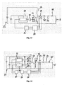
- Fig. 11 shows another block diagram illustrating the use of the PLL control device for controlling the high-frequency generator.
- the output stage 24 is formed in the example as a class D half-bridge, wherein the resonant circuit is coupled to the node 39.
- a current measuring device 23 is provided between the node 39 and a resistor 35.
- the resistor 35 represents a line resistance.
- the resistor 45 connected in series represents a coil resistance.
- a voltage is tapped. This voltage and a current measured by the current measuring device 23 are supplied to the inputs of a phase comparator 28.
- the voltage applied to the phase comparator 28 output voltage is filtered to the input of the voltage controlled oscillator 26, respectively.
- phase comparator which has the function of an error amplifier, until there is a frequency and phase equality at its inputs.
- driver stages 48, 49 are driven, which drive via transformers 50, 51 power amplifiers 52, 53 or drive.
- Fig. 12 shows a device with a high frequency generator having a class D full bridge with PLL control.
- the resonant circuit is designed as a series resonant circuit. The remaining components and their interconnection correspond to the description Fig. 11 ,
- a device is shown with a high frequency generator having a class E power amplifier with PLL control.
- the resonant circuit is designed as a series resonant circuit and comprises the coupling capacitor 22, the coupling coil 5 and the line resistor 35 and the coil resistor 45.
- the use of a class E power amplifier circuit for the high frequency generator with PLL frequency and phase control and resonant circuit coupling, in particular a series / Parallel resonant circuit including the coupling coil is preferably used in the frequency and power range of 600 kHz to 30 MHz or 1 W to 500 W.
- the coil 56 is part of the class E amplifier and many times larger than the coil 5. It serves as an energy store when the power amplifier 52 is locked. The remaining components and their interconnection correspond to the description Fig. 11 ,
- FIG. 14 Figure 12 shows an equivalent electrical circuit diagram of a device with a high frequency generator having a class D half-bridge with PLL control and additional transform up-matching.
- a transformer 57 and a capacitor 58 are connected to the output of the output stages 52, 53.
- the capacitor 58 is connected in a known manner with a center tap of the transformer 57.
- the remaining components and their interconnection correspond to the description Fig. 11 ,
- FIG. 15 an embodiment of a possible capacitive impedance transformation, which in all amplifier classes (class C, class D, class E, class F) can be used.
- the resistor 38 represents the resistance of the plasma.
- the resistor 38, a capacitor 59 may be connected in parallel.
- the resistor 60 and the capacitor 61 connected in parallel represent elements of the high-frequency generator.
- the capacitors 22, 61 represent resonant capacitors, the coil 5 is the coupling coil.
- the advantage of all the variants described is that a power coupling of the energy generated by the high frequency generator over a large power and frequency range without intermediate transformation and impedance matching network directly into the plasma of the ion or electron source is possible.
- Core of the power adjustment is the inclusion of the coupling coil, design-related coupling capacitances between the plasma and the housing of the discharge vessel and the wiring to a series / or parallel resonant circuit, and the automatic frequency and phase control of the high-frequency generator.
Landscapes
- Engineering & Computer Science (AREA)
- Chemical & Material Sciences (AREA)
- Combustion & Propulsion (AREA)
- Physics & Mathematics (AREA)
- Plasma & Fusion (AREA)
- Mechanical Engineering (AREA)
- General Engineering & Computer Science (AREA)
- Plasma Technology (AREA)
- Circuit Arrangements For Discharge Lamps (AREA)
- Electron Sources, Ion Sources (AREA)
Applications Claiming Priority (1)
| Application Number | Priority Date | Filing Date | Title |
|---|---|---|---|
| DE102007036592.8A DE102007036592B4 (de) | 2007-08-02 | 2007-08-02 | Hochfrequenzgenerator für Ionen- und Elektronenquellen |
Publications (3)
| Publication Number | Publication Date |
|---|---|
| EP2020672A2 true EP2020672A2 (fr) | 2009-02-04 |
| EP2020672A3 EP2020672A3 (fr) | 2010-11-10 |
| EP2020672B1 EP2020672B1 (fr) | 2020-05-06 |
Family
ID=39944376
Family Applications (1)
| Application Number | Title | Priority Date | Filing Date |
|---|---|---|---|
| EP08013495.0A Active EP2020672B1 (fr) | 2007-08-02 | 2008-07-26 | Générateur haute fréquence pour sources d'ions et d'électrons |
Country Status (4)
| Country | Link |
|---|---|
| US (1) | US8294370B2 (fr) |
| EP (1) | EP2020672B1 (fr) |
| DE (1) | DE102007036592B4 (fr) |
| RU (1) | RU2461908C2 (fr) |
Cited By (1)
| Publication number | Priority date | Publication date | Assignee | Title |
|---|---|---|---|---|
| EP3933884A1 (fr) * | 2020-07-01 | 2022-01-05 | Analytik Jena GmbH | Générateur pour la spectrométrie |
Families Citing this family (9)
| Publication number | Priority date | Publication date | Assignee | Title |
|---|---|---|---|---|
| DE102011076404B4 (de) | 2011-05-24 | 2014-06-26 | TRUMPF Hüttinger GmbH + Co. KG | Verfahren zur Impedanzanpassung der Ausgangsimpedanz einer Hochfrequenzleistungsversorgungsanordnung an die Impedanz einer Plasmalast und Hochfrequenzleistungsversorgungsanordnung |
| EP3340746B1 (fr) | 2016-12-22 | 2021-05-05 | Technische Hochschule Mittelhessen | Unité de commande d'un générateur haute fréquence |
| KR20180109351A (ko) * | 2017-03-28 | 2018-10-08 | 엘에스산전 주식회사 | 비례공명 전류제어기 |
| DE102017107177A1 (de) | 2017-04-04 | 2018-10-04 | Tesat-Spacecom Gmbh & Co. Kg | Frequenzregelung für einen Frequenzgenerator eines Ionentriebwerks |
| RU2695541C1 (ru) * | 2018-07-02 | 2019-07-24 | Акционерное общество "Концерн "Созвзедие" | Устройство ввода энергии в газоразрядную плазму |
| EP3754187B1 (fr) | 2019-06-18 | 2023-12-13 | ThrustMe | Générateur radio-fréquence pour source de plasma et son procédé de réglage |
| DE102020106692A1 (de) | 2020-03-11 | 2021-09-16 | Analytik Jena Gmbh | Generator für die Spektrometrie |
| CN111577564A (zh) * | 2020-06-30 | 2020-08-25 | 中国人民解放军国防科技大学 | 单级复合双脉冲增强电离型感应式脉冲等离子体推力器 |
| CN118092243B (zh) * | 2024-01-26 | 2024-08-09 | 佛山市元粒宝智能电器科技有限公司 | 一种离子量输出控制电路及方法 |
Citations (1)
| Publication number | Priority date | Publication date | Assignee | Title |
|---|---|---|---|---|
| DE19948229C1 (de) | 1999-10-07 | 2001-05-03 | Daimler Chrysler Ag | Hochfrequenz-Ionenquelle |
Family Cites Families (9)
| Publication number | Priority date | Publication date | Assignee | Title |
|---|---|---|---|---|
| US4507588A (en) * | 1983-02-28 | 1985-03-26 | Board Of Trustees Operating Michigan State University | Ion generating apparatus and method for the use thereof |
| US5965034A (en) * | 1995-12-04 | 1999-10-12 | Mc Electronics Co., Ltd. | High frequency plasma process wherein the plasma is executed by an inductive structure in which the phase and anti-phase portion of the capacitive currents between the inductive structure and the plasma are balanced |
| US5824606A (en) * | 1996-03-29 | 1998-10-20 | Lam Research Corporation | Methods and apparatuses for controlling phase difference in plasma processing systems |
| US5770922A (en) * | 1996-07-22 | 1998-06-23 | Eni Technologies, Inc. | Baseband V-I probe |
| KR100542459B1 (ko) * | 1999-03-09 | 2006-01-12 | 가부시끼가이샤 히다치 세이사꾸쇼 | 플라즈마처리장치 및 플라즈마처리방법 |
| DE10215660B4 (de) * | 2002-04-09 | 2008-01-17 | Eads Space Transportation Gmbh | Hochfrequenz-Elektronenquelle, insbesondere Neutralisator |
| US6703080B2 (en) * | 2002-05-20 | 2004-03-09 | Eni Technology, Inc. | Method and apparatus for VHF plasma processing with load mismatch reliability and stability |
| JP4901094B2 (ja) * | 2004-11-30 | 2012-03-21 | 株式会社Sen | ビーム照射装置 |
| US7459899B2 (en) * | 2005-11-21 | 2008-12-02 | Thermo Fisher Scientific Inc. | Inductively-coupled RF power source |
-
2007
- 2007-08-02 DE DE102007036592.8A patent/DE102007036592B4/de active Active
-
2008
- 2008-07-26 EP EP08013495.0A patent/EP2020672B1/fr active Active
- 2008-07-30 US US12/182,645 patent/US8294370B2/en active Active
- 2008-07-31 RU RU2008131500/07A patent/RU2461908C2/ru active
Patent Citations (1)
| Publication number | Priority date | Publication date | Assignee | Title |
|---|---|---|---|---|
| DE19948229C1 (de) | 1999-10-07 | 2001-05-03 | Daimler Chrysler Ag | Hochfrequenz-Ionenquelle |
Cited By (2)
| Publication number | Priority date | Publication date | Assignee | Title |
|---|---|---|---|---|
| EP3933884A1 (fr) * | 2020-07-01 | 2022-01-05 | Analytik Jena GmbH | Générateur pour la spectrométrie |
| US12022603B2 (en) | 2020-07-01 | 2024-06-25 | Analytik Jena Gmbh+Co. Kg | Generator for spectrometry |
Also Published As
| Publication number | Publication date |
|---|---|
| US20090058303A1 (en) | 2009-03-05 |
| EP2020672B1 (fr) | 2020-05-06 |
| EP2020672A3 (fr) | 2010-11-10 |
| DE102007036592B4 (de) | 2014-07-10 |
| DE102007036592A1 (de) | 2009-02-19 |
| RU2461908C2 (ru) | 2012-09-20 |
| US8294370B2 (en) | 2012-10-23 |
| RU2008131500A (ru) | 2010-02-10 |
Similar Documents
| Publication | Publication Date | Title |
|---|---|---|
| DE102007036592B4 (de) | Hochfrequenzgenerator für Ionen- und Elektronenquellen | |
| EP1701376B1 (fr) | Generateur de plasma sous vide | |
| DE68922807T2 (de) | Phasengeteilter Treiber für ein Plasmaätzsystem. | |
| EP0261338B1 (fr) | Source d'ions fonctionnant par induction | |
| DE69914435T2 (de) | Abstimmbare und anpassbare Resonator-Spulenanordnung für Ionenimplantation-Linearbeschleuniger | |
| DE102011076404B4 (de) | Verfahren zur Impedanzanpassung der Ausgangsimpedanz einer Hochfrequenzleistungsversorgungsanordnung an die Impedanz einer Plasmalast und Hochfrequenzleistungsversorgungsanordnung | |
| DE112013005486B4 (de) | HF-Transformator, Energieversorgung mit HF-Transformator, Ionenoptisches System mit Energieversorgungsanordnung, Verfahren zum Betreiben eines HF-Transformators zur Energieversorgung, Verfahren zum Steuern eines ionenoptischen Systems | |
| EP1062679B1 (fr) | Installation de gravure au plasma | |
| DE4112161A1 (de) | Hochspannungsgenerator fuer elektrische, kapazitive anteile enthaltende lasten, insbesondere fuer laser | |
| DE19933842A1 (de) | Vorrichtung und Verfahren zum Ätzen eines Substrates mittels eines induktiv gekoppelten Plasmas | |
| EP1410698B1 (fr) | Adaptateur d'impedance a haute frequence | |
| EP1699107A1 (fr) | Coupleur 3dB | |
| WO2005027258A1 (fr) | Hybride a 90° | |
| DE202010016850U1 (de) | HF Leistungs-Koppler | |
| EP1203396B1 (fr) | Procede de gravure d'un substrat au moyen d'un plasma inductif | |
| WO2024180075A1 (fr) | Circuit d'adaptation d'impédance pour système de traitement au plasma, et système de traitement au plasma comprenant un tel circuit d'adaptation d'impédance | |
| WO2024023244A1 (fr) | Dispositif de commande et procédé d'actionnement de circuit d'adaptation d'impédance pour un système de production de plasma et système de production de plasma de ce type | |
| DE69318137T2 (de) | Erzeugung von geladenen teilchen | |
| EP3340746A1 (fr) | Unité de commande d'un générateur haute fréquence | |
| EP3631980B1 (fr) | Ensemble amplificateur à haute fréquence et procédé pour configurer un ensemble amplificateur à haute fréquence | |
| DE10008485B4 (de) | Hochfrequenz-Anpassnetzwerk | |
| EP2993775A1 (fr) | Alimentation auxiliaire avec séparation galvanique utilisent guide diélectrique et micro-ondes | |
| DE102020106692A1 (de) | Generator für die Spektrometrie | |
| DE3608871C1 (de) | Hochfrequenzsender | |
| EP1739716A1 (fr) | Système de traitement par plasma à haute fréquence |
Legal Events
| Date | Code | Title | Description |
|---|---|---|---|
| PUAI | Public reference made under article 153(3) epc to a published international application that has entered the european phase |
Free format text: ORIGINAL CODE: 0009012 |
|
| AK | Designated contracting states |
Kind code of ref document: A2 Designated state(s): AT BE BG CH CY CZ DE DK EE ES FI FR GB GR HR HU IE IS IT LI LT LU LV MC MT NL NO PL PT RO SE SI SK TR |
|
| AX | Request for extension of the european patent |
Extension state: AL BA MK RS |
|
| PUAL | Search report despatched |
Free format text: ORIGINAL CODE: 0009013 |
|
| AK | Designated contracting states |
Kind code of ref document: A3 Designated state(s): AT BE BG CH CY CZ DE DK EE ES FI FR GB GR HR HU IE IS IT LI LT LU LV MC MT NL NO PL PT RO SE SI SK TR |
|
| AX | Request for extension of the european patent |
Extension state: AL BA MK RS |
|
| 17P | Request for examination filed |
Effective date: 20110423 |
|
| AKX | Designation fees paid |
Designated state(s): DE FR GB IT |
|
| 17Q | First examination report despatched |
Effective date: 20130219 |
|
| STAA | Information on the status of an ep patent application or granted ep patent |
Free format text: STATUS: EXAMINATION IS IN PROGRESS |
|
| RAP1 | Party data changed (applicant data changed or rights of an application transferred) |
Owner name: ARIANEGROUP GMBH |
|
| GRAP | Despatch of communication of intention to grant a patent |
Free format text: ORIGINAL CODE: EPIDOSNIGR1 |
|
| STAA | Information on the status of an ep patent application or granted ep patent |
Free format text: STATUS: GRANT OF PATENT IS INTENDED |
|
| INTG | Intention to grant announced |
Effective date: 20191205 |
|
| GRAS | Grant fee paid |
Free format text: ORIGINAL CODE: EPIDOSNIGR3 |
|
| GRAA | (expected) grant |
Free format text: ORIGINAL CODE: 0009210 |
|
| STAA | Information on the status of an ep patent application or granted ep patent |
Free format text: STATUS: THE PATENT HAS BEEN GRANTED |
|
| AK | Designated contracting states |
Kind code of ref document: B1 Designated state(s): DE FR GB IT |
|
| REG | Reference to a national code |
Ref country code: GB Ref legal event code: FG4D Free format text: NOT ENGLISH |
|
| REG | Reference to a national code |
Ref country code: DE Ref legal event code: R096 Ref document number: 502008017078 Country of ref document: DE |
|
| REG | Reference to a national code |
Ref country code: DE Ref legal event code: R119 Ref document number: 502008017078 Country of ref document: DE |
|
| PLBE | No opposition filed within time limit |
Free format text: ORIGINAL CODE: 0009261 |
|
| STAA | Information on the status of an ep patent application or granted ep patent |
Free format text: STATUS: NO OPPOSITION FILED WITHIN TIME LIMIT |
|
| 26N | No opposition filed |
Effective date: 20210209 |
|
| PG25 | Lapsed in a contracting state [announced via postgrant information from national office to epo] |
Ref country code: DE Free format text: LAPSE BECAUSE OF NON-PAYMENT OF DUE FEES Effective date: 20210202 |
|
| P01 | Opt-out of the competence of the unified patent court (upc) registered |
Effective date: 20230612 |
|
| PGFP | Annual fee paid to national office [announced via postgrant information from national office to epo] |
Ref country code: IT Payment date: 20250724 Year of fee payment: 18 |
|
| PGFP | Annual fee paid to national office [announced via postgrant information from national office to epo] |
Ref country code: GB Payment date: 20250722 Year of fee payment: 18 |
|
| PGFP | Annual fee paid to national office [announced via postgrant information from national office to epo] |
Ref country code: FR Payment date: 20250724 Year of fee payment: 18 |