EP2020724A1 - Lade-/entladesteuereinrichtung für akkumulatoren und lade-/entladesteuerverfahren - Google Patents
Lade-/entladesteuereinrichtung für akkumulatoren und lade-/entladesteuerverfahren Download PDFInfo
- Publication number
- EP2020724A1 EP2020724A1 EP07744185A EP07744185A EP2020724A1 EP 2020724 A1 EP2020724 A1 EP 2020724A1 EP 07744185 A EP07744185 A EP 07744185A EP 07744185 A EP07744185 A EP 07744185A EP 2020724 A1 EP2020724 A1 EP 2020724A1
- Authority
- EP
- European Patent Office
- Prior art keywords
- power storage
- temperature
- estimated
- soc
- outside air
- Prior art date
- Legal status (The legal status is an assumption and is not a legal conclusion. Google has not performed a legal analysis and makes no representation as to the accuracy of the status listed.)
- Granted
Links
Images







Classifications
-
- H—ELECTRICITY
- H02—GENERATION; CONVERSION OR DISTRIBUTION OF ELECTRIC POWER
- H02J—ELECTRIC POWER NETWORKS; CIRCUIT ARRANGEMENTS OR SYSTEMS FOR SUPPLYING OR DISTRIBUTING ELECTRIC POWER; SYSTEMS FOR STORING ELECTRIC ENERGY
- H02J7/00—Circuit arrangements for charging or discharging batteries or for supplying loads from batteries
- H02J7/90—Regulation of charging or discharging current or voltage
- H02J7/971—Regulation of charging or discharging current or voltage the charge cycle being controlled or terminated in response to non-electric parameters
- H02J7/975—Regulation of charging or discharging current or voltage the charge cycle being controlled or terminated in response to non-electric parameters in response to temperature
-
- B—PERFORMING OPERATIONS; TRANSPORTING
- B60—VEHICLES IN GENERAL
- B60L—PROPULSION OF ELECTRICALLY-PROPELLED VEHICLES; SUPPLYING ELECTRIC POWER FOR AUXILIARY EQUIPMENT OF ELECTRICALLY-PROPELLED VEHICLES; ELECTRODYNAMIC BRAKE SYSTEMS FOR VEHICLES IN GENERAL; MAGNETIC SUSPENSION OR LEVITATION FOR VEHICLES; MONITORING OPERATING VARIABLES OF ELECTRICALLY-PROPELLED VEHICLES; ELECTRIC SAFETY DEVICES FOR ELECTRICALLY-PROPELLED VEHICLES
- B60L3/00—Electric devices on electrically-propelled vehicles for safety purposes; Monitoring operating variables, e.g. speed, deceleration or energy consumption
- B60L3/0023—Detecting, eliminating, remedying or compensating for drive train abnormalities, e.g. failures within the drive train
- B60L3/0046—Detecting, eliminating, remedying or compensating for drive train abnormalities, e.g. failures within the drive train relating to electric energy storage systems, e.g. batteries or capacitors
-
- B—PERFORMING OPERATIONS; TRANSPORTING
- B60—VEHICLES IN GENERAL
- B60L—PROPULSION OF ELECTRICALLY-PROPELLED VEHICLES; SUPPLYING ELECTRIC POWER FOR AUXILIARY EQUIPMENT OF ELECTRICALLY-PROPELLED VEHICLES; ELECTRODYNAMIC BRAKE SYSTEMS FOR VEHICLES IN GENERAL; MAGNETIC SUSPENSION OR LEVITATION FOR VEHICLES; MONITORING OPERATING VARIABLES OF ELECTRICALLY-PROPELLED VEHICLES; ELECTRIC SAFETY DEVICES FOR ELECTRICALLY-PROPELLED VEHICLES
- B60L58/00—Methods or circuit arrangements for monitoring or controlling batteries or fuel cells, specially adapted for electric vehicles
- B60L58/10—Methods or circuit arrangements for monitoring or controlling batteries or fuel cells, specially adapted for electric vehicles for monitoring or controlling batteries
- B60L58/12—Methods or circuit arrangements for monitoring or controlling batteries or fuel cells, specially adapted for electric vehicles for monitoring or controlling batteries responding to state of charge [SoC]
- B60L58/13—Maintaining the SoC within a determined range
-
- B—PERFORMING OPERATIONS; TRANSPORTING
- B60—VEHICLES IN GENERAL
- B60L—PROPULSION OF ELECTRICALLY-PROPELLED VEHICLES; SUPPLYING ELECTRIC POWER FOR AUXILIARY EQUIPMENT OF ELECTRICALLY-PROPELLED VEHICLES; ELECTRODYNAMIC BRAKE SYSTEMS FOR VEHICLES IN GENERAL; MAGNETIC SUSPENSION OR LEVITATION FOR VEHICLES; MONITORING OPERATING VARIABLES OF ELECTRICALLY-PROPELLED VEHICLES; ELECTRIC SAFETY DEVICES FOR ELECTRICALLY-PROPELLED VEHICLES
- B60L58/00—Methods or circuit arrangements for monitoring or controlling batteries or fuel cells, specially adapted for electric vehicles
- B60L58/10—Methods or circuit arrangements for monitoring or controlling batteries or fuel cells, specially adapted for electric vehicles for monitoring or controlling batteries
- B60L58/24—Methods or circuit arrangements for monitoring or controlling batteries or fuel cells, specially adapted for electric vehicles for monitoring or controlling batteries for controlling the temperature of batteries
-
- B—PERFORMING OPERATIONS; TRANSPORTING
- B60—VEHICLES IN GENERAL
- B60W—CONJOINT CONTROL OF VEHICLE SUB-UNITS OF DIFFERENT TYPE OR DIFFERENT FUNCTION; CONTROL SYSTEMS SPECIALLY ADAPTED FOR HYBRID VEHICLES; ROAD VEHICLE DRIVE CONTROL SYSTEMS FOR PURPOSES NOT RELATED TO THE CONTROL OF A PARTICULAR SUB-UNIT
- B60W10/00—Conjoint control of vehicle sub-units of different type or different function
- B60W10/24—Conjoint control of vehicle sub-units of different type or different function including control of energy storage means
- B60W10/26—Conjoint control of vehicle sub-units of different type or different function including control of energy storage means for electrical energy, e.g. batteries or capacitors
-
- B—PERFORMING OPERATIONS; TRANSPORTING
- B60—VEHICLES IN GENERAL
- B60W—CONJOINT CONTROL OF VEHICLE SUB-UNITS OF DIFFERENT TYPE OR DIFFERENT FUNCTION; CONTROL SYSTEMS SPECIALLY ADAPTED FOR HYBRID VEHICLES; ROAD VEHICLE DRIVE CONTROL SYSTEMS FOR PURPOSES NOT RELATED TO THE CONTROL OF A PARTICULAR SUB-UNIT
- B60W20/00—Control systems specially adapted for hybrid vehicles
- B60W20/10—Controlling the power contribution of each of the prime movers to meet required power demand
- B60W20/15—Control strategies specially adapted for achieving a particular effect
-
- G—PHYSICS
- G01—MEASURING; TESTING
- G01R—MEASURING ELECTRIC VARIABLES; MEASURING MAGNETIC VARIABLES
- G01R31/00—Arrangements for testing electric properties; Arrangements for locating electric faults; Arrangements for electrical testing characterised by what is being tested not provided for elsewhere
- G01R31/36—Arrangements for testing, measuring or monitoring the electrical condition of accumulators or electric batteries, e.g. capacity or state of charge [SoC]
- G01R31/367—Software therefor, e.g. for battery testing using modelling or look-up tables
-
- G—PHYSICS
- G01—MEASURING; TESTING
- G01R—MEASURING ELECTRIC VARIABLES; MEASURING MAGNETIC VARIABLES
- G01R31/00—Arrangements for testing electric properties; Arrangements for locating electric faults; Arrangements for electrical testing characterised by what is being tested not provided for elsewhere
- G01R31/36—Arrangements for testing, measuring or monitoring the electrical condition of accumulators or electric batteries, e.g. capacity or state of charge [SoC]
- G01R31/382—Arrangements for monitoring battery or accumulator variables, e.g. SoC
-
- H—ELECTRICITY
- H01—ELECTRIC ELEMENTS
- H01M—PROCESSES OR MEANS, e.g. BATTERIES, FOR THE DIRECT CONVERSION OF CHEMICAL ENERGY INTO ELECTRICAL ENERGY
- H01M10/00—Secondary cells; Manufacture thereof
- H01M10/42—Methods or arrangements for servicing or maintenance of secondary cells or secondary half-cells
- H01M10/44—Methods for charging or discharging
-
- H—ELECTRICITY
- H01—ELECTRIC ELEMENTS
- H01M—PROCESSES OR MEANS, e.g. BATTERIES, FOR THE DIRECT CONVERSION OF CHEMICAL ENERGY INTO ELECTRICAL ENERGY
- H01M10/00—Secondary cells; Manufacture thereof
- H01M10/42—Methods or arrangements for servicing or maintenance of secondary cells or secondary half-cells
- H01M10/44—Methods for charging or discharging
- H01M10/443—Methods for charging or discharging in response to temperature
-
- H—ELECTRICITY
- H01—ELECTRIC ELEMENTS
- H01M—PROCESSES OR MEANS, e.g. BATTERIES, FOR THE DIRECT CONVERSION OF CHEMICAL ENERGY INTO ELECTRICAL ENERGY
- H01M10/00—Secondary cells; Manufacture thereof
- H01M10/42—Methods or arrangements for servicing or maintenance of secondary cells or secondary half-cells
- H01M10/48—Accumulators combined with arrangements for measuring, testing or indicating the condition of cells, e.g. the level or density of the electrolyte
-
- H—ELECTRICITY
- H01—ELECTRIC ELEMENTS
- H01M—PROCESSES OR MEANS, e.g. BATTERIES, FOR THE DIRECT CONVERSION OF CHEMICAL ENERGY INTO ELECTRICAL ENERGY
- H01M10/00—Secondary cells; Manufacture thereof
- H01M10/42—Methods or arrangements for servicing or maintenance of secondary cells or secondary half-cells
- H01M10/48—Accumulators combined with arrangements for measuring, testing or indicating the condition of cells, e.g. the level or density of the electrolyte
- H01M10/486—Accumulators combined with arrangements for measuring, testing or indicating the condition of cells, e.g. the level or density of the electrolyte for measuring temperature
-
- H—ELECTRICITY
- H02—GENERATION; CONVERSION OR DISTRIBUTION OF ELECTRIC POWER
- H02J—ELECTRIC POWER NETWORKS; CIRCUIT ARRANGEMENTS OR SYSTEMS FOR SUPPLYING OR DISTRIBUTING ELECTRIC POWER; SYSTEMS FOR STORING ELECTRIC ENERGY
- H02J7/00—Circuit arrangements for charging or discharging batteries or for supplying loads from batteries
- H02J7/14—Circuit arrangements for charging or discharging batteries or for supplying loads from batteries for charging batteries from dynamo-electric generators driven at varying speed, e.g. on vehicle
-
- B—PERFORMING OPERATIONS; TRANSPORTING
- B60—VEHICLES IN GENERAL
- B60L—PROPULSION OF ELECTRICALLY-PROPELLED VEHICLES; SUPPLYING ELECTRIC POWER FOR AUXILIARY EQUIPMENT OF ELECTRICALLY-PROPELLED VEHICLES; ELECTRODYNAMIC BRAKE SYSTEMS FOR VEHICLES IN GENERAL; MAGNETIC SUSPENSION OR LEVITATION FOR VEHICLES; MONITORING OPERATING VARIABLES OF ELECTRICALLY-PROPELLED VEHICLES; ELECTRIC SAFETY DEVICES FOR ELECTRICALLY-PROPELLED VEHICLES
- B60L2240/00—Control parameters of input or output; Target parameters
- B60L2240/60—Navigation input
- B60L2240/66—Ambient conditions
- B60L2240/662—Temperature
-
- B—PERFORMING OPERATIONS; TRANSPORTING
- B60—VEHICLES IN GENERAL
- B60L—PROPULSION OF ELECTRICALLY-PROPELLED VEHICLES; SUPPLYING ELECTRIC POWER FOR AUXILIARY EQUIPMENT OF ELECTRICALLY-PROPELLED VEHICLES; ELECTRODYNAMIC BRAKE SYSTEMS FOR VEHICLES IN GENERAL; MAGNETIC SUSPENSION OR LEVITATION FOR VEHICLES; MONITORING OPERATING VARIABLES OF ELECTRICALLY-PROPELLED VEHICLES; ELECTRIC SAFETY DEVICES FOR ELECTRICALLY-PROPELLED VEHICLES
- B60L2260/00—Operating Modes
- B60L2260/40—Control modes
- B60L2260/50—Control modes by future state prediction
- B60L2260/56—Temperature prediction, e.g. for pre-cooling
-
- B—PERFORMING OPERATIONS; TRANSPORTING
- B60—VEHICLES IN GENERAL
- B60W—CONJOINT CONTROL OF VEHICLE SUB-UNITS OF DIFFERENT TYPE OR DIFFERENT FUNCTION; CONTROL SYSTEMS SPECIALLY ADAPTED FOR HYBRID VEHICLES; ROAD VEHICLE DRIVE CONTROL SYSTEMS FOR PURPOSES NOT RELATED TO THE CONTROL OF A PARTICULAR SUB-UNIT
- B60W20/00—Control systems specially adapted for hybrid vehicles
-
- B—PERFORMING OPERATIONS; TRANSPORTING
- B60—VEHICLES IN GENERAL
- B60W—CONJOINT CONTROL OF VEHICLE SUB-UNITS OF DIFFERENT TYPE OR DIFFERENT FUNCTION; CONTROL SYSTEMS SPECIALLY ADAPTED FOR HYBRID VEHICLES; ROAD VEHICLE DRIVE CONTROL SYSTEMS FOR PURPOSES NOT RELATED TO THE CONTROL OF A PARTICULAR SUB-UNIT
- B60W2510/00—Input parameters relating to a particular sub-units
- B60W2510/24—Energy storage means
- B60W2510/242—Energy storage means for electrical energy
- B60W2510/244—Charge state
-
- B—PERFORMING OPERATIONS; TRANSPORTING
- B60—VEHICLES IN GENERAL
- B60W—CONJOINT CONTROL OF VEHICLE SUB-UNITS OF DIFFERENT TYPE OR DIFFERENT FUNCTION; CONTROL SYSTEMS SPECIALLY ADAPTED FOR HYBRID VEHICLES; ROAD VEHICLE DRIVE CONTROL SYSTEMS FOR PURPOSES NOT RELATED TO THE CONTROL OF A PARTICULAR SUB-UNIT
- B60W2510/00—Input parameters relating to a particular sub-units
- B60W2510/24—Energy storage means
- B60W2510/242—Energy storage means for electrical energy
- B60W2510/246—Temperature
-
- B—PERFORMING OPERATIONS; TRANSPORTING
- B60—VEHICLES IN GENERAL
- B60W—CONJOINT CONTROL OF VEHICLE SUB-UNITS OF DIFFERENT TYPE OR DIFFERENT FUNCTION; CONTROL SYSTEMS SPECIALLY ADAPTED FOR HYBRID VEHICLES; ROAD VEHICLE DRIVE CONTROL SYSTEMS FOR PURPOSES NOT RELATED TO THE CONTROL OF A PARTICULAR SUB-UNIT
- B60W2540/00—Input parameters relating to occupants
- B60W2540/06—Ignition switch
-
- B—PERFORMING OPERATIONS; TRANSPORTING
- B60—VEHICLES IN GENERAL
- B60W—CONJOINT CONTROL OF VEHICLE SUB-UNITS OF DIFFERENT TYPE OR DIFFERENT FUNCTION; CONTROL SYSTEMS SPECIALLY ADAPTED FOR HYBRID VEHICLES; ROAD VEHICLE DRIVE CONTROL SYSTEMS FOR PURPOSES NOT RELATED TO THE CONTROL OF A PARTICULAR SUB-UNIT
- B60W2555/00—Input parameters relating to exterior conditions, not covered by groups B60W2552/00, B60W2554/00
- B60W2555/20—Ambient conditions, e.g. wind or rain
-
- B—PERFORMING OPERATIONS; TRANSPORTING
- B60—VEHICLES IN GENERAL
- B60W—CONJOINT CONTROL OF VEHICLE SUB-UNITS OF DIFFERENT TYPE OR DIFFERENT FUNCTION; CONTROL SYSTEMS SPECIALLY ADAPTED FOR HYBRID VEHICLES; ROAD VEHICLE DRIVE CONTROL SYSTEMS FOR PURPOSES NOT RELATED TO THE CONTROL OF A PARTICULAR SUB-UNIT
- B60W30/00—Purposes of road vehicle drive control systems not related to the control of a particular sub-unit, e.g. of systems using conjoint control of vehicle sub-units
- B60W30/18—Propelling the vehicle
- B60W30/192—Mitigating problems related to power-up or power-down of the driveline, e.g. start-up of a cold engine
-
- H—ELECTRICITY
- H01—ELECTRIC ELEMENTS
- H01M—PROCESSES OR MEANS, e.g. BATTERIES, FOR THE DIRECT CONVERSION OF CHEMICAL ENERGY INTO ELECTRICAL ENERGY
- H01M10/00—Secondary cells; Manufacture thereof
- H01M10/42—Methods or arrangements for servicing or maintenance of secondary cells or secondary half-cells
- H01M10/46—Accumulators structurally combined with charging apparatus
-
- Y—GENERAL TAGGING OF NEW TECHNOLOGICAL DEVELOPMENTS; GENERAL TAGGING OF CROSS-SECTIONAL TECHNOLOGIES SPANNING OVER SEVERAL SECTIONS OF THE IPC; TECHNICAL SUBJECTS COVERED BY FORMER USPC CROSS-REFERENCE ART COLLECTIONS [XRACs] AND DIGESTS
- Y02—TECHNOLOGIES OR APPLICATIONS FOR MITIGATION OR ADAPTATION AGAINST CLIMATE CHANGE
- Y02E—REDUCTION OF GREENHOUSE GAS [GHG] EMISSIONS, RELATED TO ENERGY GENERATION, TRANSMISSION OR DISTRIBUTION
- Y02E60/00—Enabling technologies; Technologies with a potential or indirect contribution to GHG emissions mitigation
- Y02E60/10—Energy storage using batteries
-
- Y—GENERAL TAGGING OF NEW TECHNOLOGICAL DEVELOPMENTS; GENERAL TAGGING OF CROSS-SECTIONAL TECHNOLOGIES SPANNING OVER SEVERAL SECTIONS OF THE IPC; TECHNICAL SUBJECTS COVERED BY FORMER USPC CROSS-REFERENCE ART COLLECTIONS [XRACs] AND DIGESTS
- Y02—TECHNOLOGIES OR APPLICATIONS FOR MITIGATION OR ADAPTATION AGAINST CLIMATE CHANGE
- Y02T—CLIMATE CHANGE MITIGATION TECHNOLOGIES RELATED TO TRANSPORTATION
- Y02T10/00—Road transport of goods or passengers
- Y02T10/60—Other road transportation technologies with climate change mitigation effect
- Y02T10/70—Energy storage systems for electromobility, e.g. batteries
-
- Y—GENERAL TAGGING OF NEW TECHNOLOGICAL DEVELOPMENTS; GENERAL TAGGING OF CROSS-SECTIONAL TECHNOLOGIES SPANNING OVER SEVERAL SECTIONS OF THE IPC; TECHNICAL SUBJECTS COVERED BY FORMER USPC CROSS-REFERENCE ART COLLECTIONS [XRACs] AND DIGESTS
- Y02—TECHNOLOGIES OR APPLICATIONS FOR MITIGATION OR ADAPTATION AGAINST CLIMATE CHANGE
- Y02T—CLIMATE CHANGE MITIGATION TECHNOLOGIES RELATED TO TRANSPORTATION
- Y02T10/00—Road transport of goods or passengers
- Y02T10/60—Other road transportation technologies with climate change mitigation effect
- Y02T10/72—Electric energy management in electromobility
-
- Y—GENERAL TAGGING OF NEW TECHNOLOGICAL DEVELOPMENTS; GENERAL TAGGING OF CROSS-SECTIONAL TECHNOLOGIES SPANNING OVER SEVERAL SECTIONS OF THE IPC; TECHNICAL SUBJECTS COVERED BY FORMER USPC CROSS-REFERENCE ART COLLECTIONS [XRACs] AND DIGESTS
- Y02—TECHNOLOGIES OR APPLICATIONS FOR MITIGATION OR ADAPTATION AGAINST CLIMATE CHANGE
- Y02T—CLIMATE CHANGE MITIGATION TECHNOLOGIES RELATED TO TRANSPORTATION
- Y02T90/00—Enabling technologies or technologies with a potential or indirect contribution to GHG emissions mitigation
- Y02T90/10—Technologies relating to charging of electric vehicles
- Y02T90/16—Information or communication technologies improving the operation of electric vehicles
Definitions
- the present invention relates generally to apparatuses and methods for controlling charging and discharging rechargeable power storage devices and particularly to technology employed to ensure that a vehicular system that has been shut down restarts.
- Hybrid vehicles, electric vehicles and other similar motored vehicles capable of generating electric power while they are traveling have a secondary battery, an electric double layer capacitor or a similar power storage device mounted therein.
- the hybrid vehicle has a motor generator converting the electric power that is stored in the power storage device into a driving power which is in turn transmitted to a wheel singly or together with a driving power that the engine generates.
- a secondary battery stores electrical energy by utilizing a chemical reaction. Accordingly, its charging and discharging characteristics significantly vary with environmental factors, temperature conditions in particular. More specifically, at low temperatures, the chemical reaction has a significantly decreased level of reactivity and the secondary battery may not be able to discharge sufficient electric power. As such, in early winter morning or in cold climate areas, the secondary battery can only supply decreased electric power, and in a hybrid vehicle configured to have a motor generator crank the engine to start, for example its vehicular system including the engine cannot be started. Such temperature dependence is exhibited more significantly in particular by a lithium ion battery than a nickel metal hydride battery, as the former has a higher energy density than the latter.
- the electric double layer capacitor is also temperature-dependent and can only supply decreased electric power at low temperatures.
- Japanese Patent Laying-Open No. 11-355967 discloses a battery control apparatus improving an engine's startablility at low temperatures.
- This battery control apparatus includes: temperature estimation means for estimating the temperature that a battery has when an engine next starts; SOC setting means setting the battery's SOC corresponding to the battery's estimated value in temperature for obtaining a predetermined output from the battery; SOC detection means for detecting the battery's SOC; and means for controlling charging and discharging the battery to allow the battery's detected SOC value to attain the set SOC value.
- the temperature estimation means estimates the temperature that the battery has when the engine next starts, as based on the value of an outside air temperature detected when the engine was previously started.
- the battery control apparatus can provide an output required to start the engine if the battery has a low temperature when the engine is next started.
- Japanese Patent Laying-Open No. 11-355967 discloses that a temperature that the battery has when the engine next starts is estimated from the value of an outside air temperature detected when the engine was previously started
- the publication does not specifically disclose how the temperature that the battery has when the engine next starts is estimated from the value of the outside air temperature detected when the engine was previously started.
- the present invention has been made to solve such problem and it contemplates an apparatus and method for the vehicle of interest for controlling charging and discharging a power storage device as well as estimating an optimal power storage temperature to ensure that a vehicular system having been shut down restarts.
- the present invention in one aspect provides an apparatus controlling charging and discharging a rechargeable power storage device mounted in a vehicle, comprising: means for obtaining outside air temperature representing a temperature outside the vehicle; means for obtaining estimated power storage temperature based on the outside air temperature obtained by the means for obtaining outside air temperature, the estimated power storage temperature representing an estimated value of a temperature that the power storage device has when an ignition-on command is received to restart a vehicular system, the means for obtaining estimated power storage temperature having the estimated power storage temperature stored therein in association with the outside air temperature; means for obtaining actual power storage temperature representing an actual value of a temperature of the power storage device; and means for learning, updating a relationship between the outside air temperature and the estimated power storage temperature in the means for obtaining estimated power storage temperature, as based on an error between the estimated power storage temperature previously obtained by the means for obtaining estimated power storage temperature and the actual power storage temperature obtained when the ignition-on command is received.
- the means for obtaining estimated power storage temperature obtains estimated power storage temperature based on the outside air temperature obtained by the means for obtaining outside air temperature.
- the estimated power storage temperature is an estimated value of a temperature that the power storage device will have when an ignition-on command is received to restart a vehicular system.
- Means for learning updates a relationship between the outside air temperature and the estimated power storage temperature in the means for obtaining estimated power storage temperature, as based on an error between the estimated power storage temperature previously obtained by the means for obtaining estimated power storage temperature and the actual power storage temperature obtained when the ignition-on command is received.
- the relationship between the outside air temperature and the estimated power storage temperature is optimized for the vehicle of interest. The temperature that the power storage device has when a command to restart a vehicular system is received can thus be optimally estimated from outside air temperature.
- the means for learning updates the relationship to associate a value obtained from a function including the estimated power storage temperature and the actual power storage temperature with the outside air temperature used to obtain that estimated power storage temperature.
- the apparatus controlling charging and discharging a power storage device further comprises: means for obtaining SOC of the power storage device; and means for controlling an amount charged into/discharged from the power storage device to maintain the SOC obtained by the means for obtaining SOC within a predetermined control range in accordance with the estimated power storage temperature.
- the means for obtaining estimated power storage temperature successively obtains the estimated power storage temperature while the vehicular system is active.
- the means for controlling an amount charged/discharged further includes means for converting the SOC obtained by the means for obtaining SOC into a corrected SOC in accordance with the estimated power storage temperature for controlling charging and discharging.
- the vehicle includes an engine configured to be capable of driving generation means for charging the power storage device and the engine is configured to be started by electric power discharged from the power storage device.
- the means for controlling an amount charged/discharged includes means for starting the engine to allow the SOC to be within the predetermined control range if the SOC is not within the predetermined control range when the ignition-off command is received.
- the means for obtaining estimated power storage temperature includes an estimated power storage map having more than one component of estimated power storage temperature stored therein with the outside air temperature serving as a parameter.
- the estimated power storage map further has in addition to the outside air temperature as a further parameter at least one of: a time zone in which the ignition-off command is received; the actual power storage temperature obtained when the previous ignition-on command is immediately previously received; and a period of duration for which the vehicular system is active.
- the present invention in another aspect provides an apparatus controlling charging and discharging a rechargeable power storage device mounted in a vehicle, comprising: a unit obtaining outside air temperature representing a temperature outside the vehicle; a unit obtaining actual power storage temperature representing an actual value of a temperature of the power storage device; and a control device including a storage unit, wherein: the control device obtains estimated power storage temperature based on the outside air temperature obtained by the unit obtaining outside air temperature, the estimated power storage temperature representing an estimated value of a temperature that the power storage device has when an ignition-on command is received to restart a vehicular system; the storage unit has the estimated power storage temperature stored therein in association with the outside air temperature; and the control device updates a relationship between the outside air temperature and the estimated power storage temperature stored in the storage unit, as based on an error between the estimated power storage temperature previously obtained and the actual power storage temperature obtained when the ignition-on command is received.
- the present invention in still another aspect provides a method for controlling charging and discharging a rechargeable power storage device mounted in a vehicle, comprising the steps of: obtaining an outside air temperature representing a temperature outside the vehicle; referring to a previously stored relationship between estimated power storage temperature and the outside air temperature, as based on the outside air temperature obtained, to obtain estimated power storage temperature representing an estimated value of a temperature that the power storage device has when an ignition-on command is received to restart a vehicular system; obtaining actual power storage temperature representing an actual value of a temperature of the power storage device; and updating the previously stored relationship between the estimated power storage temperature and the outside air temperature, as based on an error between the estimated power storage temperature previously obtained and the actual power storage temperature obtained when the ignition-on command is received.
- the present invention can thus implement an apparatus controlling charging and discharging a power storage device, that can estimate an optimal estimated power storage temperature for each vehicle to ensure that a vehicular system having been shut down restarts.
- a vehicle 100 is a hybrid vehicle including a secondary battery BAT, system relays SR1 and SR2, a power control unit (PCU) 8, a motor generator (MG) 10, an engine 9, and a power split device 11.
- PCU power control unit
- MG motor generator
- Secondary battery BAT is a set of batteries configured of a plurality of series connected battery modules each formed of a plurality of battery cells integrated together. By way of example, it is configured of a lithium ion battery, a nickel metal hydride battery or the like. Secondary battery BAT has its positive and negative electrodes connected via system relays SR1 and SR2, respectively, to PCU 8 and is charged or discharged in amounts, respectively, as controlled by PCU 8.
- PCU 8 When vehicle 100 is in a running mode, PCU 8 receives direct current electric power (discharged electric power) from secondary battery BAT, converts it into alternate current electric power and supplies it to motor generator 10. When vehicle 100 is regeneratively braked, PCU 8 converts alternate current electric power generated by motor generator 10 into direct current electric power (charged electric power) and supplies it to secondary battery BAT to recover kinetic energy of vehicle 100 as electrical energy. Furthermore, PCU 8 may include a boost/buck converter (a DC/DC converter) that steps up direct current voltage received from secondary battery BAT and steps down direct current voltage received from motor generator 10.
- boost/buck converter a DC/DC converter
- regenerative braking as referred to herein includes: braking accompanied by power-generating braking when a driver of a hybrid vehicle operates the foot brake; not operating the foot brake, while releasing the accelerator pedal while the vehicle is traveling, to reduce vehicular speed (or stop acceleration) while providing power-generating braking; and the like.
- Motor generator 10 is for example a 3-phase alternate current rotating electric machine. It receives alternate current electric power from PCU 8 to work as a motor to generate a driving power causing vehicle 100 to travel, while it also receives a driving power transmitted from engine 9 or a wheel (not shown) to work as an electric power generator to generate electric power from the kinetic energy of vehicle 100 to charge secondary battery BAT.
- motor generator 10 is configured to be drivable by engine 9.
- Engine 9 generates a driving power from combusted gasoline, light oil, methanol or similar fuel and provides the generated driving power via power split device 11 to a wheel (not shown) or motor generator 10.
- Power split device 11 is a device communicating a driving power between motor generator 10, engine 9 and a wheel (not shown). By way of example, it is configured of a single pinion type planetary gear device.
- motor generator 10 receives electric power discharged from secondary battery BAT to generate a driving power to crank (or rotatively drive) engine 9.
- crank or rotatively drive
- engine 9 As engine 9 is cranked, fuel is injected and ignited and engine 9 establishes continuous rotation.
- Such cranking of engine 9 by motor generator 10 is implemented by operating power split device 11 to transmit to engine 9 the driving power generated by motor generator 10.
- controlling charging and discharging secondary battery BAT is implemented as an adjusting operation for discharged power and/or charged power by controlling motor generator 10 (or PCU 8) and/or engine 9.
- vehicle 100 includes a control device 1, a voltage measurement unit 12, a current measurement unit 14, a battery temperature measurement unit 16, an outside air temperature measurement unit 18, and an engine ECU 7.
- Control device 1 is connected to voltage measurement unit 12 measuring actual voltage Vb of secondary battery BAT, current measurement unit 14 measuring actual current Ib of secondary battery BAT, and battery temperature measurement unit 16 measuring actual battery temperature Tb of secondary battery BAT, and control device 1 successively obtains a state of charge (SOC) indicating an amount remaining in secondary battery BAT, as based on secondary battery BAT's actual voltage Vb, actual current Ib and actual battery temperature Tb.
- SOC state of charge
- the SOC will be represented in percentages with secondary battery BAT's fully charged amount serving as a reference (i.e., 100%). Such representation in percentages may be replaced with an SOC represented for example by an absolute value (Ah) of a remaining amount.
- Secondary battery BAT's SOC can be obtained by employing a variety of well known techniques.
- control device 1 successively detects SOC by adding together a provisional SOC calculated from actual voltage Vb in open circuit (or an open-circuit voltage value) and a compensatory SOC calculated from a cumulative value of actual current Ib.
- control device 1 calculates electric power Wout allowed to be discharged and electric power Win allowed to be charged.
- Electric power Wout allowed to be discharged and electric power Win allowed to be charged are limit values for discharged power and charged power, respectively, at each time point that are applied for a short time, as defined by a limit in terms of chemical reaction.
- control device 1 is configured to receive an ignition-off command IGOFF and an ignition-on command IGON for shutting down and starting, respectively, a vehicular system.
- the vehicular system as referred to herein includes each device, including engine 9, configuring vehicle 100, and in particular, includes devices operating directly or indirectly on electric power output from secondary battery BAT.
- control device 1 is also connected to outside air temperature measurement unit 18 measuring temperature Tout of air outside vehicle 100. Based on outside air temperature Tout measured by outside air temperature measurement unit 18, control device 1 obtains an estimated battery temperature #Tb indicating an estimated value of a temperature that secondary battery BAT will have when ignition-on command IGON is received to restart the vehicular system.
- control device 1 when the vehicular system is active, control device 1 successively obtains estimated battery temperature #Tb, and controls an amount charged into/discharged from secondary battery BAT in order to maintain its SOC within a predetermined control range based on estimated battery temperature #Tb. More specifically, control device 1 issues a control command to PCU 8 to control the amount charged into/discharged from secondary battery BAT and also controls via engine ECU 7 the driving power generated by engine 9. Note that engine ECU 7 operates in response to a control command issued from control device 1 to adjust an amount of fuel or the like supplied to engine 9 to control the driving power generated by engine 9 (or its rotation speed).
- control device 1 when control device 1 receives ignition-on command IGON, control device 1 activates system relay commands SRC1, SRC2 to drive system relays SR1, SR2, respectively, on to electrically connect secondary battery BAT and PCU 8 together. In contrast, when control device 1 receives ignition-off command IGOFF, control device 1 deactivates system relay commands SRC1, SRC2 to turn off system relays SR1, SR2, respectively (i.e., the system is shut down).
- Control device 1 is configured for example of an electrical control unit (ECU) and the like and includes a random access memory (RAM) 4, an estimated battery temperature map 5, and a central processing unit (CPU) 6.
- ECU electrical control unit
- RAM random access memory
- CPU central processing unit
- CPU 6 performs a variety of processes in control device 1, as described above, in accordance with a program, a map and the like previously stored in RAM 4, and obtains data as the processes are performed. CPU 6 stores the data to RAM 4.
- Estimated battery temperature map 5 is configured in the form for example of electrical erasable and programmable read only memory (EEPROM) or a similar data-writable, non-volatile storage medium.
- Estimated battery temperature map 5 stores estimated battery temperature #Tb therein in association with outside air temperature Tout. More specifically, estimated battery temperature map 5 has a plurality of components of estimated battery temperature #Tb stored therein with outside air temperature Tout serving as a parameter.
- CPU 2 refers to estimated battery temperature map 5 and obtains therefrom estimated battery temperature #Tb corresponding to outside air temperature Tout obtained from outside air temperature measurement unit 18.
- estimated battery temperature map 5 has estimated battery temperature #Tb stored therein in association with outside air temperature Tout.
- Fig. 2 shows, by way of example, outside air temperature Tout defined for every 5°C in a range of -30°C to 30°C.
- estimated battery temperature map 5 is not limited to such configuration. Estimated battery temperature map 5 may be configured considering: how precisely charging and discharging secondary battery BAT of interest is controlled; in what environment it is used; and the like. Note that, as will be described later, estimated battery temperature map 5 has stored therein estimated battery temperature #Tb updated as a learning process is performed, and for an initial value therefor, the map may have stored therein a value obtained experimentally in advance.
- CPU 6 performs the learning process updating a relationship between outside air temperature Tout and estimated battery temperature #Tb stored in estimated battery temperature map 5, as based on an error between estimated battery temperature #Tb as previously obtained and outside air temperature Tout obtained when the subsequent ignition-on command IGON is received. More specifically, a value of a component in estimated battery temperature map 5 is updated to a result value obtained from a function including estimated battery temperature #Tb and outside air temperature Tout so that the value is associated with outside air temperature Tout used (or set as a parameter) to obtain that estimated battery temperature #Tb.
- Control device 1 corresponds to "an apparatus for controlling charging and discharging a power storage device".
- CPU 6 implements "means for obtaining outside air temperature", “means for obtaining actual power storage temperature”, “means for learning”, and “means for controlling an amount charged into/discharged”.
- CPU 6 and estimated battery temperature map 5 implement "means for obtaining estimated power storage temperature”.
- estimated battery temperature #Tb corresponds to "estimated power storage temperature”.
- Actual battery temperature Tb corresponds to "actual power storage temperature”.
- Estimated battery temperature map 5 corresponds to an "estimated power storage temperature map”.
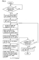
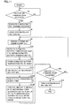
- FIG. 3 describes a general flow of a process performed by an apparatus for controlling charging and discharging a power storage device in accordance with the first embodiment of the present invention.
- step S2 determines whether ignition-on command IGON is received (step S2). If ignition-on command IGON is not received (NO at step S2), CPU 6 waits until ignition-on command IGON is received (step S2).
- step S2 If ignition-on command IGON is received (YES at step S2), CPU 6 performs a subroutine of a learning process (step S4), and CPU 6 activates system relay commands SRC1, SRC2 to drive system relays SR1, SR2 on (step S6).
- CPU 6 obtains outside air temperature Tout from outside air temperature measurement unit 18 (step S8) and refers to estimated battery temperature map 5 to obtain estimated battery temperature #Tb corresponding to outside air temperature Tout obtained in step S8 (step S10). Furthermore, CPU 6 stores to RAM 4 the estimated battery temperature #Tb obtained at step S10 (step S12).
- CPU 6 obtains secondary battery BAT's SOC based on secondary battery BAT's actual voltage Vb, actual current Ib, actual battery temperature Tb and the like (step S 14), and from the obtained estimated battery temperature #Tb, CPU 6 determines a control range in which to exert control to charge/discharge secondary battery BAT (step S16). Furthermore, CPU 6 controls an amount charged into/discharged from secondary battery BAT in order to maintain its SOC within the control range determined in step S16 (step S 18).
- CPU 6 determines whether ignition-off command IGOFF is received (step S20). If ignition-off command IGOFF is not received (NO at step S20), CPU 6 repeats steps S8-S20.
- step S20 If ignition-off command IGOFF is received (YES at step S20), CPU 6 deactivates system relay commands SRC1, SRC2 to turn off system relays SR1, SR2 (step S24) and thus end the process.
- step S10 After ignition-on command IGON is received while the vehicular system is active CPU 6 successively obtains estimated battery temperature #Tb (step S10), since it is impossible to predict at which time point (or timing of processing) ignition-off command IGOFF is received, and accordingly, charging and discharging secondary battery BAT is controlled to ensure that the vehicular system can be restarted, whichever time point ignition-off command IGOFF may be received at.
- CPU 6 controls charging and discharging in order to maintain the battery BAT SOC within a predetermined control range.
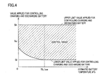
- the control range in which to exert control to charge/discharge the battery is defined by upper and lower limit values applied for controlling charging and discharging the battery.
- the upper and lower limit values are set to include a center value Sc applied for controlling charging and discharging the battery.
- CPU 6 varies the lower limit value applied for controlling charging and discharging the battery, as based on estimated battery temperature #Tb obtained. More specifically, if estimated battery temperature #Tb is higher than a threshold value Tb_low for estimated low temperature, CPU 6 controls charging and discharging within a range of a lower limit value S1 to an upper limit value Sh. If estimated battery temperature #Tb does not exceed threshold value Tb_low for estimated low temperature, the lower limit value applied for controlling charging and discharging the battery is changed to a value larger than lower limit value Sl.
- CPU 6 maintains secondary battery BAT's SOC within a higher range to ensure that the vehicular system restarts.
- the lower limit value applied for controlling charging and discharging the battery may be charged, depending on the driver's operation, to a value larger than lower limit value Sl as normally applied for controlling charging and discharging the battery.
- Such configuration allows controlling charging and discharging the battery to be adjusted at a relatively large degree of freedom when a vehicle runs in a different driving pattern than normal, such as traveling to a cold climate area.
- CPU 6 updates a relationship between outside air temperature Tout and estimated battery temperature #Tb stored in estimated battery temperature map 5, as based on an error between estimated battery temperature #Tb as previously obtained and outside air temperature Tout obtained when the subsequent ignition-on command IGON is received.
- a vehicle used daily such as for commutation, business and the like is often used in relatively analogous driving patterns.
- vehicle When the vehicle is used in such a manner, its vehicular system is kept inactive for analogous periods. Accordingly the battery also shows relatively analogous tendencies in what characteristic actual battery temperature Tb exhibits as it drops after ignition-off command IGOFF is received before ignition-on command IGON is again received.
- the present invention in the first embodiment provides an apparatus controlling charging and discharging a power storage device, that stores in estimated battery temperature map 5 a plurality of components of estimated battery temperature #Tb, stratified by outside air temperature Tout affecting the value of actual battery temperature Tb, and that modifies the stored value of estimated battery temperature #Tb to match actual battery temperature Tb.
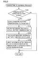
- the learning process has the subroutine providing a process in a flow, as will be described hereinafter.
- CPU 6 determines whether RAM 4 has estimated battery temperature #Tb stored therein (step S100). If RAM 4 does not have estimated battery temperature #Tb stored therein (NO at step S100), CPU 6 returns to a former process.
- RAM 4 has estimated battery temperature #Tb stored therein (YES at step S100)
- CPU 6 reads estimated battery temperature #Tb from RAM 4 (step S102). Note that if estimated battery temperature #Tb read from RAM 4 for example exceeds a predetermined range, then, to avoid updating estimated battery temperature map 5 by an outlier, the control may interrupt a subsequent process and return to a former process.
- CPU 6 updates the estimated battery temperature #Tb of interest stored in estimated battery temperature map 5 to be the modified, estimated battery temperature #Tb_NEW obtained (step S108), and CPU 6 returns to a former process.
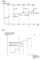
- Fig. 6 shows how estimated battery temperature #Tb corresponding to outside air temperature Tout of a particular value in estimated battery temperature map 5 (for example in Fig. 2 when outside air temperature Tout is 0°C) varies with time, by way of example.
- the vehicular system is shut down and started repeatedly in accordance with ignition-off command IGOFF and ignition-on command IGON alternately received.
- outside air temperature Tout has an approximately constant value (e.g., 0°C) when ignition-off command IGOFF is received (i.e., at times t1, t3, t5).
- ignition-off command IGOFF(1) is received for a first time.
- CPU 6 refers to estimated battery temperature map 5 to obtain estimated battery temperature #Tb(1) corresponding to outside air temperature Tout obtained at time t1.
- ignition-on command IGON(1) is received for a first time.
- CPU 6 obtains actual battery temperature Tb(1) at time t2, and calculates a modified, estimated battery temperature #Tb_NEW(1) from estimated battery temperature #Tb(1) and actual battery temperature Tb(1) for ignition-on command IGON(1) received for the first time.
- CPU 6 updates in estimated battery temperature map 5 a value corresponding to outside air temperature Tout obtained at time t1 to the modified, estimated battery temperature #Tb_NEW(1).
- ignition-off command IGOFF(2) is received for a second time.
- CPU 6 refers to estimated battery temperature map 5 to obtain estimated battery temperature #Tb(2) corresponding to outside air temperature Tout obtained at time t3.
- outside air temperature Tout corresponds to a value that has been updated to estimated battery temperature #Tb_NEW(1)
- estimated battery temperature #Tb(2) matches estimated battery temperature #Tb_NEW(1).
- Such learning process modifies estimated battery temperature #Tb stored in estimated battery temperature map 5, i.e., provides modified estimated battery temperature #Tb_NEW, in a direction to match actual battery temperature Tb.
- estimated battery temperature #Tb corresponding to one outside air temperature Tout stored in estimated battery temperature map 5 is noted to exemplify how estimated battery temperature #Tb varies with time.
- the learning process is performed independently by each unit of outside air temperature Tout (or by each stratified unit) as defined in estimated battery temperature map 5 in accordance with outside air temperature Tout obtained when ignition-off command IGOFF is received.
- estimated battery temperature map 5 has estimated battery temperature #Tb updated in a process, as will be described hereinafter.
- Fig. 7 represents estimated battery temperature #Tb stored in estimated battery temperature map 5, with an axis of abscissas representing outside air temperature Tout serving as a parameter.
- Estimated battery temperature map 5 has a plurality of components of estimated battery temperature #Tb stored therein in association with its defined outside air temperature Tout (stratified). As has been described above, the learning control is executed by each unit of outside air temperature Tout (or by each stratified unit) independently. Accordingly, whenever the learning control is executed, one estimated battery temperature #Tb associated with one outside air temperature Tout will be updated.
- estimated battery temperature map 5 is updated to have estimated battery temperature #Tb_NEW based on an error between estimated battery temperature #Tb previously obtained and actual battery temperature Tb obtained when ignition-on command IGON is received.
- estimated battery temperature #Tb in accordance with a driving pattern performed on a daily basis can be learnt at least for each outside air temperature Tout, and whenever ignition-on command IGON and ignition-off command IGOFF are repeated, estimated battery temperature map 5 can have its stored estimated battery temperature #Tb updated to a value adapted to the vehicle of interest.
- an optimal estimated battery temperature can be estimated for each vehicle, and an apparatus controlling charging and discharging a power storage device can be implemented that ensures that a vehicular system having been shut down restarts.
- the present invention in the first embodiment ensures that a vehicular system having been shut down restarts, and thus it is not necessary to adopt second battery BAT that has excessive chargeable capacity against decreased temperature when the vehicular system restarts.
- Secondary battery BAT can thus have a capacity determined without considering power dischargeability in restarting the vehicular system.
- Secondary battery BAT can hence have a capacity determined by noting the vehicle's motive power performance or the like alone. The vehicle can thus mount therein secondary battery BAT optimized in capacity.
- the present invention in the first embodiment illustrates an estimated battery temperature map having a plurality of components of estimated battery temperature #Tb stored therein in association with outside air temperature Tout.
- the map may have a plurality of components of estimated battery temperature #Tb stored therein in association with outside air temperature Tout and in addition thereto another parameter.
- a vehicle used for commutation has its vehicular system having been shut down in a time zone and inactive for a period of time before departing for work, and having been shut down in a different time zone and inactive for a different period of time before departing from work.
- outside air temperature Tout is the same
- actual battery temperature Tb may vary with when the vehicular system restarts. More specifically, when the vehicle departs for work (e.g., in the morning) the vehicular system has been inactive since ignition-off command IGOFF was received in the previous day when the vehicle arrived home from work (e.g., in the evening). In contrast, when the vehicle departs from work (e.g., in the evening), the vehicular system has been inactive since ignition-off command IGOFF was received in the same day when the vehicle arrived at work (e.g., in the morning).
- an estimated battery temperature map 5A may be provided that has the components of estimated battery temperature #Tb stored therein in association with outside air temperature Tout and in addition thereto a time zone in which ignition-off command IGOFF is received.
- estimated battery temperature map 5A has the components of estimated battery temperature #Tb stored therein such that outside air temperature Tout and in addition a time zone in which ignition-off command IGOFF is received (e.g., morning, afternoon, evening, and late night and early morning) serve as parameters.
- a time zone in which ignition-off command IGOFF is received e.g., morning, afternoon, evening, and late night and early morning
- the above described learning process is performed on a time zone basis, and a result of the learning process will clearly be distinguished by when the vehicle arrives at work and when it arrives home from work, and thus reflected.
- the present invention in the first embodiment in the first exemplary variation can achieve an effect of the first embodiment, as described above, and in addition thereto an effect of a learning process for different time zones. If a single vehicle is used in a plurality of different driving patterns, the battery's estimated temperature can be learnt for each driving pattern.
- a parameter associated with estimated battery temperature #Tb may be actual battery temperature Tb that secondary battery BAT had when the previous ignition-off command IGOFF was received.
- an estimated battery temperature map 5B has the components of estimated battery temperature #Tb stored therein such that outside air temperature Tout and in addition thereto actual battery temperature Tb that secondary battery BAT had when the previous ignition-off command IGOFF was received serve as parameters.
- a vehicle used for commutation or the like will be used in two driving patterns for going to work and leaving work, respectively. If at least these two driving patterns can be distinguished, charging and discharging the battery can appropriately be controlled and the learning process can appropriately be performed.
- the driving patterns for going to work and leaving work, respectively are repeated alternately. Accordingly, on the basis of a difference that actual battery temperature Tb had when the previous ignition-off command IGOFF was received, a decision can be made on which driving pattern a driving pattern is.
- the present invention in the first embodiment in the second exemplary variation can provide an effect of the first embodiment, as described above, and in addition thereto an effect of a learning process for different actual battery temperature Tb that a battery had when the previous ignition-off command IGOFF was received. If a single vehicle is used in a plurality of driving patterns, an estimated battery temperature can be learnt for each driving pattern.
- a parameter associated with estimated battery temperature #Tb may be a period of duration for which a vehicular system is active.
- an estimated battery temperature map 5C has the components of estimated battery temperature #Tb stored therein such that outside air temperature Tout and in addition thereto a period of duration for which the vehicular system is active serve as parameters. Note that the period of duration for which the vehicular system is active is obtained by measuring a period of time that has elapsed up to the present since the previous ignition-on command IGON was received.
- a vehicle used on weekdays for commutation for a relatively small distance is used for example on a holiday to go for a long drive
- its vehicular system operates for a period of time different in length from that of weekend, and it can be determined that the vehicle is in a different pattern from the other.
- the present invention in the first embodiment in the third exemplary variation can provide an effect of the first embodiment, as described above, and in addition thereto an effect of a learning process by a distinctive period of duration for which a vehicular system is active. If a single vehicle is used in a plurality of driving patterns, an estimated battery temperature can be learnt for each driving pattern.
- a three or four dimensional estimated battery temperature map may be used that has combined the parameters described in the first embodiment in the first to third exemplary variations. Furthermore any parameter other than those described above may be used that can identify a plurality of driving patterns.
- the present invention in the first embodiment has been described for a configuration controlling charging and discharging secondary battery BAT, in which a lower limit value applied for the controlling is varied based on estimated battery temperature #Tb obtained.
- the present invention in a second embodiment will be described for a configuration converting an actual SOC value to a corrected SOC for the controlling based on estimated battery temperature #Tb obtained.
- the present invention in the second embodiment controls charging and discharging secondary battery BAT by converting secondary battery BAT's SOC to a corrected SOC based on obtained estimated battery temperature #Tb to allow the present invention to be applied to an existing system without varying the lower limit value applied for controlling charging and discharging the battery. More specifically, if it is necessary that the lower limit value applied for controlling charging and discharging the battery be varied to a higher value, the lower limit value applied for controlling charging and discharging the battery is not varied. Instead, secondary battery BAT's actual SOC is converted to a corrected SOC indicating a lower value to provide a substantially the same effect.
- the present invention in the second embodiment provides an apparatus controlling charging and discharging a power storage device, that is similar to that described in the first embodiment and shown in Fig. 1 . Accordingly it will not be described in detail. Note that in the present invention in the second embodiment CPU 6 implements a "means for converting SOC".
- the apparatus controlling charging and discharging a power storage device in accordance with the present invention in the second embodiment provides a process generally having a flow as will be described hereinafter. This flow corresponds to that described in the first embodiment as shown in Fig. 3 having steps S16 and S18 replaced with steps S16# and S18#.
- step S16# CPU 6 performs an SOC conversion subroutine. More specifically, CPU 6 converts secondary battery BAT's SOC that is obtained in step S 14 to a corrected SOC (hereinafter also referred to as #SOC) in accordance with estimated battery temperature #Tb obtained at step S10. Furthermore, CPU 6 controls an amount charged into/discharged from secondary battery BAT to maintain #SOC (the corrected SOC) that has been obtained at step S16# within a predetermined control range (step S18#).
- #SOC corrected SOC
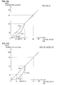
- Figs. 12A and 12B are diagrams for illustrating how secondary battery BAT's SOC (an actual value) is converted to #SOC (a corrected SOC). Note that in the following description, secondary battery BAT's SOC detected as based on actual voltage Vb, actual current Ib, actual battery temperature Tb and the like will also be referred to as an "SOC (actual value)" for the sake of clarification.
- CPU 6 determines an SOC conversion function (by way of example, SOC conversion function F0(x) or F1(x)) in accordance with estimated battery temperature #Tb obtained, and CPU 6 uses the conversion function to convert an SOC (actual value) to a #SOC (corrected SOC).
- SOC conversion function F0(x) or F1(x) in accordance with estimated battery temperature #Tb obtained, and CPU 6 uses the conversion function to convert an SOC (actual value) to a #SOC (corrected SOC).
- CPU 6 selects SOC conversion function F0(x) that sets #SOC (corrected SOC) as the same value of SOC (actual value). Then, controlling charging and discharging the battery in accordance with #SOC (the corrected SOC) matches a result of controlling charging and discharging the battery in accordance with SOC (actual value).
- CPU 6 selects SOC conversion function F1(x) for a range of SOC (actual value) smaller than center value Sc applied for controlling charging and discharging the battery, to convert SOC (actual value) to a lower #SOC (corrected SOC). Then, when #SOC (the corrected SOC) is lower limit value Sl applied for controlling charging and discharging the battery, the corresponding SOC (actual value) assumes a lower limit value #S1(T1) applied for controlling charging and discharging the battery, that is higher than lower limit value Sl applied for controlling charging and discharging the battery.
- controlling charging and discharging the battery in order to maintain #SOC (a corrected SOC) within a range of lower limit value Sl to upper limit value Sh substantially means controlling charging and discharging the battery in order to maintain SOC (actual value) within a range of lower limit value #S1(T1) to upper limit value Sh.
- the present invention in the second embodiment provides an apparatus controlling charging and discharging a power storage device, that can substantially vary a control range in which to exert control to charge/discharge the power storage device in accordance with estimated battery temperature #Tb to allow secondary battery BAT to have an SOC maintained in a higher range.
- SOC conversion function F2(x) an SOC (actual value) corresponding to #SOC (a corrected SOC) having the same value as lower limit value Sl assumes a lower limit value #Sl(T2) applied for controlling charging and discharging the battery, that is higher than lower limit value #Sl(T1).
- a control range in which to exert control to charge/discharge secondary battery BAT can have a lower limit value limited to be higher to ensure that a vehicular system starts.
- CPU 6 determines an appropriate SOC conversion function in accordance with estimated battery temperature #Tb obtained and uses the determined SOC conversion function to convert an SOC (actual value) to #SOC (a corrected SOC).
- CPU 6 determines an SOC conversion function in accordance with estimated battery temperature #Tb obtained (step S200).
- CPU 6 substitutes the obtained SOC (actual value) in the determined SOC conversion function to calculate an SOC conversion function output value F(SOC) (step S202). Then, CPU 6 determines whether
- ⁇ represents a one-step variation. More specifically, CPU 6 determines whether a deviation of the current #SOC (the corrected SOC) and SOC conversion function output value F (SOC) is less than one-step variation ⁇ to prevent #SOC (the corrected SOC) from instantly, significantly varying.
- CPU 6 determines whether F(SOC) > #SOC (the corrected SOC) is satisfied (step S208). More specifically, CPU 6 determines in which direction #SOC (the corrected SOC) should be varied in accordance with which one of the current #SOC (the corrected SOC) and SOC conversion function output value F(SOC) is larger than the other, and CPU 6 varies #SOC (the corrected SOC) by one-step variation ⁇ through the following steps:
- an SOC conversion function of a severer direction i.e., a direction in which estimated battery temperature #Tb is lower
- a less severe direction i.e., a direction in which estimated battery temperature #Tb is higher
- the present invention in the second embodiment provides an effect of the first embodiment and in addition controls charging and discharging a battery on the assumption that SOC has a lower value than an obtained SOC by using an SOC conversion function determined in accordance with estimated battery temperature #Tb.
- lower limit value Sl defining a control range in SOC in which to exert control to charge/discharge the battery is not directly varied and can be limited to a substantially higher range.
- the present invention can be applied without affecting other control and function utilizing lower limit value Sl applied for controlling charging and discharging the battery.
- the present invention in the first embodiment is described for such a configuration that while a vehicular system is active, estimated battery temperature #Tb is successively obtained and secondary battery BAT is charged/discharged in an amount controlled to have an SOC within a predetermined control range based on estimated battery temperature #Tb.
- the present invention in a third embodiment will be described for a configuration continuing the engine's operation if secondary battery BAT does not have an SOC within a predetermined control range when ignition-off command IGOFF is received.
- the present invention in the third embodiment provides an apparatus controlling charging and discharging a power storage device, that is similar to that described in the first embodiment with reference to Fig. 1 . Accordingly, it will not be described repeatedly in detail. Note that in the third embodiment CPU 6 implements "means for actuating the engine".
- the apparatus controlling charging and discharging a power storage device in accordance with the third embodiment provides a process having a flow generally as will be described hereinafter. This flow corresponds to that described in the first embodiment as shown in Fig. 3 minus steps S8-S18 and plus steps S30, S32, S34, S36, S38.
- step S6 CPU 6 determines whether ignition-off command IGOFF is received (step S20). If not (NO at step S20), CPU 6 waits until ignition-off command IGOFF is received (step S20).
- CPU 6 obtains outside air temperature Tout from outside air temperature measurement unit 18 (step S30), and refers to estimated battery temperature map 5 to obtain estimated battery temperature #Tb corresponding to outside air temperature Tout obtained at step S30 (step S32). Furthermore, CPU 6 stores to RAM 4 the estimated battery temperature #Tb obtained at step S32 (step S34). Furthermore, CPU 6 obtains secondary battery BAT's SOC based on secondary battery BAT's actual voltage Vb, actual current Ib, actual battery temperature Tb and the like (step S36).
- CPU 6 performs a shutdown control subroutine (step S38). More specifically, if secondary battery BAT does not have an SOC within a predetermined control range, CPU 6 actuates engine 9 to bring the SOC within the predetermined control range, and once secondary battery BAT has attained an SOC falling within the predetermined control range, CPU 6 shuts down the vehicular system. Once the shutdown control subroutine (step S38) has completed, CPU 6 deactivates system relay commands SRC1, SRC2 to cause system relays SR1, SR2 to transition to be off (step S24), and thus ends the process.
- steps S30-S36 in the flow of the process performed by the apparatus controlling charging and discharging a power storage device in accordance with the third embodiment of the present invention are similar to steps S8-S 14 in the flow of the process performed by the apparatus controlling charging and discharging a power storage device in accordance with the first embodiment of the present invention shown in Fig. 3 .
- CPU 6 actuates engine 9 to cause motor generator 10 to generate electric power to charge secondary battery BAT to the predetermined control range, and then shuts down the vehicular system.
- controlling charging and discharging secondary battery BAT ensures that the vehicular system is restarted.
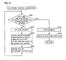
- the shutdown control subroutine provides a process having a flow as will be described hereinafter.
- CPU 6 determines whether secondary battery BAT has an SOC (actual value) exceeding a lower limit value applied for controlling charging and discharging the battery (step S300).
- CPU 6 If the SOC (actual value) does not exceed the lower limit value applied for controlling charging and discharging the battery (NO at step S300), CPU 6 provides a command to engine ECU 7 to actuate engine 9 (step S302). Note that if engine 9 is inactive when ignition-off command IGOFF is received, CPU 6 starts engine 9, and CPU 6 controls an amount of electric power that motor generator 10 generates, as based on secondary battery BAT's SOC (actual value), such that electric power Win allowed to be charged is not exceeded (step S304).
- CPU 6 obtains secondary battery BAT's SOC (actual value) (step S306), and CPU 6 again determines whether the SOC (actual value) exceeds the lower limit value applied for controlling charging and discharging the battery (step S300).
- CPU 6 issues a command to engine ECU 7 to stop engine 9 (step S310), and CPU 6 performs a shutdown process for other devices contained in the vehicular system (step S312). Subsequently CPU 6 returns to a previous process.
- CPU 6 confirms that secondary battery BAT has been charged to an extent ensuring that a vehicular system can be restarted, and thereafter CPU 6 shuts down the vehicular system.
- the present invention in the third embodiment can provide an effect of the first embodiment, and, in addition, starts engine 9 to charge secondary battery BAT if secondary battery BAT does not have an SOC within a control range in which to exert control to charge/discharge secondary battery BAT when ignition-off command IGOFF is received. This ensures that the vehicular system having been shut down restarts, whichever value of SOC secondary battery BAT may have when ignition-off command IGOFF is received.
- the present invention in a fourth embodiment provides an apparatus controlling charging and discharging a power storage device, that is similar to that is described in accordance with the present invention in the first embodiment shown in Fig. 1 . Accordingly, it will not be described repeatedly in detail.
- the apparatus controlling charging and discharging a power storage device in accordance with the fourth embodiment of the present invention performs a process having a flow generally as will be described hereinafter.
- This flow corresponds to that described in the first embodiment as shown in Fig. 3 having steps S16 and S18 replaced with steps S16# and S18# and also having a step S38 added thereto.
- Steps S16# and S18# and the SOC conversion subroutine have specifically been described in the second embodiment of the present invention, as described above. Accordingly, they will not be described repeatedly in detail. Furthermore, step S38 and the control subroutine have specifically been described in the third embodiment of the present invention, as described above. Accordingly, they will not be described repeatedly in detail. Note that the general flow of the process performed by the apparatus controlling charging and discharging a power storage device in accordance with the fourth embodiment of the present invention may have the Fig. 14 steps S30, S32, S34, S36 eliminated therefrom, as preceding steps (steps S8-S14) are similar thereto.
- the present invention in the fourth embodiment can provide the effects of the first to third embodiments simultaneously.
- the present invention in the first to fourth embodiments and the first embodiment's exemplary variations has been described for a vehicle having mounted therein the present apparatus controlling charging and discharging a power storage device.
- the present invention is also applicable to any apparatuses and systems with a secondary battery that is susceptible to variation in temperature.
- the present invention in the first to fourth embodiments and the first embodiment's exemplary variations has been described by way of example for a configuration implementing "means for obtaining estimated battery temperature" by an estimated battery temperature map having a plurality of components of estimated battery temperature #Tb stored therein in association with outside air temperature Tout.
- a function having outside air temperature Tout as a variable may be used to calculate estimated battery temperature #Tb successively. In that case, a constant term defining the function will be updated by learning-control.
- the present invention in the first to fourth embodiments has been described for a configuration that applies the present apparatus controlling charging and discharging a power storage device to a secondary battery. It is needless to say, however, that the present invention is applicable not only to the secondary battery but also to a capacitor and other similar power storage device that have a characteristic in temperature reducing electric power that they can supply at low temperatures.
Landscapes
- Engineering & Computer Science (AREA)
- Transportation (AREA)
- Chemical & Material Sciences (AREA)
- Mechanical Engineering (AREA)
- Power Engineering (AREA)
- Electrochemistry (AREA)
- Manufacturing & Machinery (AREA)
- Chemical Kinetics & Catalysis (AREA)
- General Chemical & Material Sciences (AREA)
- Sustainable Energy (AREA)
- Sustainable Development (AREA)
- Life Sciences & Earth Sciences (AREA)
- Combustion & Propulsion (AREA)
- Automation & Control Theory (AREA)
- Physics & Mathematics (AREA)
- General Physics & Mathematics (AREA)
- Secondary Cells (AREA)
- Electric Propulsion And Braking For Vehicles (AREA)
- Charge And Discharge Circuits For Batteries Or The Like (AREA)
- Tests Of Electric Status Of Batteries (AREA)
- Hybrid Electric Vehicles (AREA)
Applications Claiming Priority (2)
| Application Number | Priority Date | Filing Date | Title |
|---|---|---|---|
| JP2006141792A JP4929839B2 (ja) | 2006-05-22 | 2006-05-22 | 蓄電装置の充放電制御装置 |
| PCT/JP2007/060751 WO2007136126A1 (ja) | 2006-05-22 | 2007-05-21 | 蓄電装置の充放電制御装置および充放電制御方法 |
Publications (3)
| Publication Number | Publication Date |
|---|---|
| EP2020724A1 true EP2020724A1 (de) | 2009-02-04 |
| EP2020724A4 EP2020724A4 (de) | 2013-08-07 |
| EP2020724B1 EP2020724B1 (de) | 2016-06-22 |
Family
ID=38723434
Family Applications (1)
| Application Number | Title | Priority Date | Filing Date |
|---|---|---|---|
| EP07744185.5A Active EP2020724B1 (de) | 2006-05-22 | 2007-05-21 | Lade-/entladesteuereinrichtung für akkumulatoren und lade-/entladesteuerverfahren |
Country Status (8)
| Country | Link |
|---|---|
| US (1) | US8078417B2 (de) |
| EP (1) | EP2020724B1 (de) |
| JP (1) | JP4929839B2 (de) |
| KR (1) | KR20090016471A (de) |
| CN (1) | CN101449448B (de) |
| CA (1) | CA2651141C (de) |
| RU (1) | RU2403663C2 (de) |
| WO (1) | WO2007136126A1 (de) |
Cited By (6)
| Publication number | Priority date | Publication date | Assignee | Title |
|---|---|---|---|---|
| WO2012076928A1 (en) | 2010-12-09 | 2012-06-14 | Renault Trucks | Method for controlling a hybrid automotive vehicle and hybrid vehicle adapted to such a method |
| WO2014158489A1 (en) * | 2013-03-14 | 2014-10-02 | Motorola Mobility Llc | Method and apparatus for determining a thermal state of a battery taking into account battery aging |
| FR3027259A1 (fr) * | 2014-10-21 | 2016-04-22 | Renault Sa | Procede de pilotage et de regulation thermique d'un systeme de prolongation d'autonomie d'un vehicule automobile |
| GB2538332A (en) * | 2015-05-15 | 2016-11-16 | Tata Motors European Technical Ct Plc | Thermal Mapping Method And Apparatus |
| FR3041914A1 (fr) * | 2015-10-05 | 2017-04-07 | Renault Sas | Procede de determination des plages d'utilisation d'une batterie de traction |
| WO2018234405A1 (de) * | 2017-06-21 | 2018-12-27 | Bayerische Motoren Werke Aktiengesellschaft | Energieversorgungseinrichtung für ein kraftfahrzeug |
Families Citing this family (28)
| Publication number | Priority date | Publication date | Assignee | Title |
|---|---|---|---|---|
| US7647205B2 (en) * | 2006-06-07 | 2010-01-12 | Gm Global Technology Operations, Inc. | Method and apparatus for management of an electric energy storage device to achieve a target life objective |
| US7730984B2 (en) * | 2006-06-07 | 2010-06-08 | Gm Global Technology Operations, Inc. | Method and apparatus for control of a hybrid electric vehicle to achieve a target life objective for an energy storage device |
| JP4774430B2 (ja) * | 2008-09-24 | 2011-09-14 | 本田技研工業株式会社 | 電気自動車及び蓄電装置の制御方法 |
| JP4683137B2 (ja) * | 2009-03-14 | 2011-05-11 | トヨタ自動車株式会社 | 動力伝達装置の制御装置 |
| KR20110054135A (ko) * | 2009-11-17 | 2011-05-25 | 현대자동차주식회사 | 하이브리드 차량의 배터리 soc 밸런싱 제어 방법 |
| JP5708070B2 (ja) * | 2011-03-11 | 2015-04-30 | 日産自動車株式会社 | バッテリ温度制御装置 |
| US9601814B2 (en) | 2011-06-24 | 2017-03-21 | Usa Clean, Inc. | Battery maintenance alert device and process |
| JP5604394B2 (ja) * | 2011-09-22 | 2014-10-08 | 株式会社日立製作所 | 電気自動車の消費電力量提供システム |
| EP2969684B1 (de) | 2013-03-14 | 2025-05-07 | Allison Transmission, Inc. | System und verfahren zur kompensation eines turboloches bei hybridfahrzeugen |
| CN105102287B (zh) | 2013-03-14 | 2019-04-12 | 艾里逊变速箱公司 | 用于混合动力电动车再生模式期间能量管理的系统和方法 |
| EP2969681B1 (de) | 2013-03-14 | 2021-02-24 | Allison Transmission, Inc. | System und verfahren zur optimierung von nutzungsbeschränkungen einer hybridfahrzeugbatterie |
| WO2014158826A1 (en) | 2013-03-14 | 2014-10-02 | Allison Transmission, Inc. | System and method for engine driveline disconnect during regeneration in hybrid vehicles |
| KR102116701B1 (ko) | 2013-03-15 | 2020-06-01 | 알리손 트랜스미션, 인크. | 하이브리드 자동차들을 위한 서비스 차단 인터로크 시스템 및 방법 |
| CN105142963B (zh) | 2013-03-15 | 2018-02-06 | 艾里逊变速箱公司 | 用于平衡混合动力车辆中的能量存储模块的荷电状态的系统及方法 |
| EP2969683A4 (de) | 2013-03-15 | 2017-01-25 | Allison Transmission, Inc. | System und verfahren für energieratenausgleich in hybriden automatischen getrieben |
| JP5928385B2 (ja) * | 2013-03-22 | 2016-06-01 | トヨタ自動車株式会社 | 蓄電システム |
| KR101558363B1 (ko) * | 2013-12-12 | 2015-10-07 | 현대자동차 주식회사 | 배터리의 충방전 제어 방법 및 시스템 |
| JP6520506B2 (ja) * | 2014-09-03 | 2019-05-29 | 株式会社デンソー | 車両の走行制御システム |
| US10099562B2 (en) * | 2014-10-15 | 2018-10-16 | Johnson Controls Technology Company | Cooling strategy for battery systems |
| KR101755800B1 (ko) * | 2015-07-03 | 2017-07-10 | 현대자동차주식회사 | 차량의 충전제어 방법 |
| JP6562856B2 (ja) * | 2016-03-17 | 2019-08-21 | 株式会社クボタ | 多目的車両 |
| FR3070346B1 (fr) * | 2017-08-30 | 2021-01-01 | Renault Sas | Procede de gestion de l'etat de charge d'un vehicule hybride |
| JP6951665B2 (ja) * | 2018-02-16 | 2021-10-20 | トヨタ自動車株式会社 | リチウムイオンキャパシタの制御装置 |
| CN112519635B (zh) * | 2019-09-17 | 2023-10-20 | 深圳市英维克科技股份有限公司 | 一种电池热管理的控制方法及相关装置 |
| CN112498172B (zh) * | 2020-02-25 | 2022-07-15 | 长城汽车股份有限公司 | 动力电池荷电状态下限控制方法、装置及车辆 |
| CN114103921B (zh) * | 2020-08-27 | 2023-12-12 | 比亚迪股份有限公司 | 车辆保电控制方法、装置及可读存储介质 |
| JP7597488B2 (ja) * | 2022-06-21 | 2024-12-10 | 株式会社クボタ | ハイブリッドシステム |
| JP2025037735A (ja) * | 2023-09-06 | 2025-03-18 | 本田技研工業株式会社 | 制御装置および制御方法 |
Family Cites Families (15)
| Publication number | Priority date | Publication date | Assignee | Title |
|---|---|---|---|---|
| JPS63209436A (ja) * | 1987-02-25 | 1988-08-31 | 東光株式会社 | 充電器 |
| JP2554899B2 (ja) * | 1987-10-26 | 1996-11-20 | 日本電信電話株式会社 | 整流器の出力電圧制御方式 |
| JP3287943B2 (ja) | 1994-03-10 | 2002-06-04 | マツダ株式会社 | ハイブリッド車両の制御装置 |
| RU2131158C1 (ru) * | 1996-07-31 | 1999-05-27 | Кубанский государственный технологический университет | Устройство автоматического контроля технического состояния элементов аккумуляторной батареи |
| JPH11332016A (ja) | 1998-05-19 | 1999-11-30 | Nissan Motor Co Ltd | ハイブリッド車両の充電制御装置 |
| JP3864560B2 (ja) * | 1998-06-03 | 2007-01-10 | 日産自動車株式会社 | バッテリー制御装置 |
| JP3549806B2 (ja) | 2000-03-01 | 2004-08-04 | 株式会社日立製作所 | 自動車用電源の制御装置 |
| FI108969B (fi) | 2000-03-14 | 2002-04-30 | Ensto Electric Oy | Sähköverkon haaroitusosa |
| DE10012353A1 (de) * | 2000-03-14 | 2001-09-20 | Man Nutzfahrzeuge Ag | Verfahren zur Spannungsvorgabe für die Generatorregelung eines Kraftfahrzeuges |
| JP2002051405A (ja) | 2000-07-31 | 2002-02-15 | Sanyo Electric Co Ltd | ハイブリッド電気自動車 |
| JP2003244862A (ja) * | 2002-02-15 | 2003-08-29 | Sumitomonacco Materials Handling Co Ltd | 車両用バッテリ充電装置 |
| JP2004245190A (ja) | 2003-02-17 | 2004-09-02 | Nissan Motor Co Ltd | ハイブリッド車両 |
| JP4736317B2 (ja) * | 2003-11-14 | 2011-07-27 | ソニー株式会社 | バッテリーパック及びバッテリー残量算出方法 |
| JP2005335443A (ja) * | 2004-05-24 | 2005-12-08 | Fujitsu Ten Ltd | バッテリー管理装置 |
| US20080014852A1 (en) * | 2006-07-11 | 2008-01-17 | Mielke Richard A | Air conditioner control for vehicular no-idle system using batteries |
-
2006
- 2006-05-22 JP JP2006141792A patent/JP4929839B2/ja active Active
-
2007
- 2007-05-21 CN CN2007800183886A patent/CN101449448B/zh active Active
- 2007-05-21 RU RU2008150486/07A patent/RU2403663C2/ru active
- 2007-05-21 WO PCT/JP2007/060751 patent/WO2007136126A1/ja not_active Ceased
- 2007-05-21 KR KR1020087029920A patent/KR20090016471A/ko not_active Ceased
- 2007-05-21 CA CA2651141A patent/CA2651141C/en active Active
- 2007-05-21 EP EP07744185.5A patent/EP2020724B1/de active Active
- 2007-05-21 US US12/226,530 patent/US8078417B2/en active Active
Cited By (14)
| Publication number | Priority date | Publication date | Assignee | Title |
|---|---|---|---|---|
| US9403527B2 (en) | 2010-12-09 | 2016-08-02 | Volvo Truck Corporation | Method for controlling a hybrid automotive vehicle and hybrid vehicle adapted to such a method |
| WO2012076928A1 (en) | 2010-12-09 | 2012-06-14 | Renault Trucks | Method for controlling a hybrid automotive vehicle and hybrid vehicle adapted to such a method |
| WO2014158489A1 (en) * | 2013-03-14 | 2014-10-02 | Motorola Mobility Llc | Method and apparatus for determining a thermal state of a battery taking into account battery aging |
| FR3027259A1 (fr) * | 2014-10-21 | 2016-04-22 | Renault Sa | Procede de pilotage et de regulation thermique d'un systeme de prolongation d'autonomie d'un vehicule automobile |
| WO2016062783A1 (en) * | 2014-10-21 | 2016-04-28 | Renault S.A.S. | Method for driving and thermally regulating a range extending system for a motor vehicle |
| US10688872B2 (en) | 2014-10-21 | 2020-06-23 | Renault S.A.S. | Method for driving and thermally regulating a range extending system for a motor vehicle |
| GB2538332B (en) * | 2015-05-15 | 2017-09-06 | Tata Motors European Technical Ct Plc | Thermal Mapping Method And Apparatus |
| GB2538332A (en) * | 2015-05-15 | 2016-11-16 | Tata Motors European Technical Ct Plc | Thermal Mapping Method And Apparatus |
| FR3041914A1 (fr) * | 2015-10-05 | 2017-04-07 | Renault Sas | Procede de determination des plages d'utilisation d'une batterie de traction |
| EP3153369A1 (de) * | 2015-10-05 | 2017-04-12 | Renault S.A.S. | Verfahren zur bestimmung der verwendungsbereiche einer traktionsbatterie |
| WO2018234405A1 (de) * | 2017-06-21 | 2018-12-27 | Bayerische Motoren Werke Aktiengesellschaft | Energieversorgungseinrichtung für ein kraftfahrzeug |
| CN110650859A (zh) * | 2017-06-21 | 2020-01-03 | 宝马股份公司 | 用于机动车的能量供应装置 |
| US11214167B2 (en) | 2017-06-21 | 2022-01-04 | Bayerische Motoren Werke Aktiengesellschaft | Energy supply device for a motor vehicle |
| CN110650859B (zh) * | 2017-06-21 | 2023-10-20 | 宝马股份公司 | 用于机动车的能量供应装置 |
Also Published As
| Publication number | Publication date |
|---|---|
| CN101449448B (zh) | 2012-06-06 |
| WO2007136126A1 (ja) | 2007-11-29 |
| KR20090016471A (ko) | 2009-02-13 |
| RU2403663C2 (ru) | 2010-11-10 |
| EP2020724A4 (de) | 2013-08-07 |
| CA2651141A1 (en) | 2007-11-29 |
| CA2651141C (en) | 2013-04-23 |
| US20090099800A1 (en) | 2009-04-16 |
| US8078417B2 (en) | 2011-12-13 |
| EP2020724B1 (de) | 2016-06-22 |
| RU2008150486A (ru) | 2010-06-27 |
| JP4929839B2 (ja) | 2012-05-09 |
| JP2007311309A (ja) | 2007-11-29 |
| CN101449448A (zh) | 2009-06-03 |
Similar Documents
| Publication | Publication Date | Title |
|---|---|---|
| EP2020724B1 (de) | Lade-/entladesteuereinrichtung für akkumulatoren und lade-/entladesteuerverfahren | |
| JP5730501B2 (ja) | 電動車両およびその制御方法 | |
| EP2363329B1 (de) | Hybridfahrzeug und hybridfahrzeugsteuerverfahren | |
| JP4434302B2 (ja) | ハイブリッド車両の制御装置およびハイブリッド車両 | |
| EP3825193B1 (de) | Leistungsregelungsvorrichtung und leistungsregelungsverfahren für hybridfahrzeug | |
| EP2725685B1 (de) | Ladungsvorrichtung für eine energiespeichervorrichtung und fahrzeug, in dem dieselbe montiert ist | |
| EP2719572B1 (de) | Elektrofahrzeug und steuerungsverfahren für ein elektrofahrzeug | |
| US10562395B2 (en) | Control device for hybrid vehicle and control method for hybrid vehicle | |
| US9776635B2 (en) | Apparatus and method to maximize vehicle functionality and fuel economy with improved drivability during engine auto stop-start operations | |
| EP2676856B1 (de) | Elektrisch angetriebenes fahrzeug und verfahren zum steuern desselben | |
| JP2008024124A (ja) | 車両用電源の制御装置およびその制御方法 | |
| JP6028328B2 (ja) | ハイブリッド車両 | |
| JP5733198B2 (ja) | ハイブリッド車両 | |
| JP2009290951A (ja) | 蓄電手段制御装置および電気自動車 | |
| JP2009273326A (ja) | 蓄電装置の制御装置 | |
| JP2012010503A (ja) | 電動車両の電源システム | |
| JP2009107554A (ja) | 動力出力装置、それを備えた車両および動力出力装置の制御方法 | |
| JP2007237809A (ja) | 車両用電源システム |
Legal Events
| Date | Code | Title | Description |
|---|---|---|---|
| PUAI | Public reference made under article 153(3) epc to a published international application that has entered the european phase |
Free format text: ORIGINAL CODE: 0009012 |
|
| 17P | Request for examination filed |
Effective date: 20081031 |
|
| AK | Designated contracting states |
Kind code of ref document: A1 Designated state(s): AT BE BG CH CY CZ DE DK EE ES FI FR GB GR HU IE IS IT LI LT LU LV MC MT NL PL PT RO SE SI SK TR |
|
| AX | Request for extension of the european patent |
Extension state: AL BA HR MK RS |
|
| DAX | Request for extension of the european patent (deleted) | ||
| RBV | Designated contracting states (corrected) |
Designated state(s): DE FR |
|
| RAP1 | Party data changed (applicant data changed or rights of an application transferred) |
Owner name: TOYOTA JIDOSHA KABUSHIKI KAISHA |
|
| A4 | Supplementary search report drawn up and despatched |
Effective date: 20130710 |
|
| RIC1 | Information provided on ipc code assigned before grant |
Ipc: B60L 11/18 20060101ALI20130704BHEP Ipc: B60L 3/00 20060101ALI20130704BHEP Ipc: H02J 7/10 20060101ALI20130704BHEP Ipc: H01M 10/48 20060101ALI20130704BHEP Ipc: B60W 30/192 20120101ALI20130704BHEP Ipc: H02J 7/04 20060101AFI20130704BHEP Ipc: H01M 10/46 20060101ALI20130704BHEP Ipc: H01M 10/44 20060101ALI20130704BHEP Ipc: B60W 20/00 20060101ALI20130704BHEP Ipc: G01R 31/36 20060101ALI20130704BHEP Ipc: B60W 10/26 20060101ALI20130704BHEP |
|
| GRAP | Despatch of communication of intention to grant a patent |
Free format text: ORIGINAL CODE: EPIDOSNIGR1 |
|
| INTG | Intention to grant announced |
Effective date: 20160108 |
|
| GRAS | Grant fee paid |
Free format text: ORIGINAL CODE: EPIDOSNIGR3 |
|
| GRAA | (expected) grant |
Free format text: ORIGINAL CODE: 0009210 |
|
| AK | Designated contracting states |
Kind code of ref document: B1 Designated state(s): DE FR |
|
| REG | Reference to a national code |
Ref country code: DE Ref legal event code: R096 Ref document number: 602007046722 Country of ref document: DE |
|
| REG | Reference to a national code |
Ref country code: DE Ref legal event code: R084 Ref document number: 602007046722 Country of ref document: DE |
|
| REG | Reference to a national code |
Ref country code: DE Ref legal event code: R097 Ref document number: 602007046722 Country of ref document: DE |
|
| PLBE | No opposition filed within time limit |
Free format text: ORIGINAL CODE: 0009261 |
|
| STAA | Information on the status of an ep patent application or granted ep patent |
Free format text: STATUS: NO OPPOSITION FILED WITHIN TIME LIMIT |
|
| 26N | No opposition filed |
Effective date: 20170323 |
|
| REG | Reference to a national code |
Ref country code: FR Ref legal event code: ST Effective date: 20180131 |
|
| PG25 | Lapsed in a contracting state [announced via postgrant information from national office to epo] |
Ref country code: FR Free format text: LAPSE BECAUSE OF NON-PAYMENT OF DUE FEES Effective date: 20170531 |
|
| P01 | Opt-out of the competence of the unified patent court (upc) registered |
Effective date: 20230517 |
|
| PGFP | Annual fee paid to national office [announced via postgrant information from national office to epo] |
Ref country code: DE Payment date: 20250325 Year of fee payment: 19 |