EP2020726A2 - Verfahren zur Einspeisung von Notfall-Hilfsladungen, Hilfswandler und Schienenfahrzeug für dieses Verfahren - Google Patents
Verfahren zur Einspeisung von Notfall-Hilfsladungen, Hilfswandler und Schienenfahrzeug für dieses Verfahren Download PDFInfo
- Publication number
- EP2020726A2 EP2020726A2 EP08161463A EP08161463A EP2020726A2 EP 2020726 A2 EP2020726 A2 EP 2020726A2 EP 08161463 A EP08161463 A EP 08161463A EP 08161463 A EP08161463 A EP 08161463A EP 2020726 A2 EP2020726 A2 EP 2020726A2
- Authority
- EP
- European Patent Office
- Prior art keywords
- phase
- auxiliary
- voltage
- switching
- phase voltage
- Prior art date
- Legal status (The legal status is an assumption and is not a legal conclusion. Google has not performed a legal analysis and makes no representation as to the accuracy of the status listed.)
- Granted
Links
Images



Classifications
-
- H—ELECTRICITY
- H02—GENERATION; CONVERSION OR DISTRIBUTION OF ELECTRIC POWER
- H02J—ELECTRIC POWER NETWORKS; CIRCUIT ARRANGEMENTS OR SYSTEMS FOR SUPPLYING OR DISTRIBUTING ELECTRIC POWER; SYSTEMS FOR STORING ELECTRIC ENERGY
- H02J9/00—Circuit arrangements for emergency or stand-by power supply, e.g. for emergency lighting
- H02J9/04—Circuit arrangements for emergency or stand-by power supply, e.g. for emergency lighting in which the distribution system is disconnected from the normal source and connected to a standby source
- H02J9/06—Circuit arrangements for emergency or stand-by power supply, e.g. for emergency lighting in which the distribution system is disconnected from the normal source and connected to a standby source with automatic change-over, e.g. UPS systems
- H02J9/062—Circuit arrangements for emergency or stand-by power supply, e.g. for emergency lighting in which the distribution system is disconnected from the normal source and connected to a standby source with automatic change-over, e.g. UPS systems for AC powered loads
-
- H—ELECTRICITY
- H02—GENERATION; CONVERSION OR DISTRIBUTION OF ELECTRIC POWER
- H02J—ELECTRIC POWER NETWORKS; CIRCUIT ARRANGEMENTS OR SYSTEMS FOR SUPPLYING OR DISTRIBUTING ELECTRIC POWER; SYSTEMS FOR STORING ELECTRIC ENERGY
- H02J7/00—Circuit arrangements for charging or discharging batteries or for supplying loads from batteries
-
- B—PERFORMING OPERATIONS; TRANSPORTING
- B60—VEHICLES IN GENERAL
- B60L—PROPULSION OF ELECTRICALLY-PROPELLED VEHICLES; SUPPLYING ELECTRIC POWER FOR AUXILIARY EQUIPMENT OF ELECTRICALLY-PROPELLED VEHICLES; ELECTRODYNAMIC BRAKE SYSTEMS FOR VEHICLES IN GENERAL; MAGNETIC SUSPENSION OR LEVITATION FOR VEHICLES; MONITORING OPERATING VARIABLES OF ELECTRICALLY-PROPELLED VEHICLES; ELECTRIC SAFETY DEVICES FOR ELECTRICALLY-PROPELLED VEHICLES
- B60L1/00—Supplying electric power to auxiliary equipment of vehicles
-
- B—PERFORMING OPERATIONS; TRANSPORTING
- B60—VEHICLES IN GENERAL
- B60L—PROPULSION OF ELECTRICALLY-PROPELLED VEHICLES; SUPPLYING ELECTRIC POWER FOR AUXILIARY EQUIPMENT OF ELECTRICALLY-PROPELLED VEHICLES; ELECTRODYNAMIC BRAKE SYSTEMS FOR VEHICLES IN GENERAL; MAGNETIC SUSPENSION OR LEVITATION FOR VEHICLES; MONITORING OPERATING VARIABLES OF ELECTRICALLY-PROPELLED VEHICLES; ELECTRIC SAFETY DEVICES FOR ELECTRICALLY-PROPELLED VEHICLES
- B60L1/00—Supplying electric power to auxiliary equipment of vehicles
- B60L1/003—Supplying electric power to auxiliary equipment of vehicles to auxiliary motors, e.g. for pumps, compressors
-
- B—PERFORMING OPERATIONS; TRANSPORTING
- B60—VEHICLES IN GENERAL
- B60L—PROPULSION OF ELECTRICALLY-PROPELLED VEHICLES; SUPPLYING ELECTRIC POWER FOR AUXILIARY EQUIPMENT OF ELECTRICALLY-PROPELLED VEHICLES; ELECTRODYNAMIC BRAKE SYSTEMS FOR VEHICLES IN GENERAL; MAGNETIC SUSPENSION OR LEVITATION FOR VEHICLES; MONITORING OPERATING VARIABLES OF ELECTRICALLY-PROPELLED VEHICLES; ELECTRIC SAFETY DEVICES FOR ELECTRICALLY-PROPELLED VEHICLES
- B60L1/00—Supplying electric power to auxiliary equipment of vehicles
- B60L1/14—Supplying electric power to auxiliary equipment of vehicles to electric lighting circuits
- B60L1/16—Supplying electric power to auxiliary equipment of vehicles to electric lighting circuits fed by the power supply line
-
- B—PERFORMING OPERATIONS; TRANSPORTING
- B60—VEHICLES IN GENERAL
- B60L—PROPULSION OF ELECTRICALLY-PROPELLED VEHICLES; SUPPLYING ELECTRIC POWER FOR AUXILIARY EQUIPMENT OF ELECTRICALLY-PROPELLED VEHICLES; ELECTRODYNAMIC BRAKE SYSTEMS FOR VEHICLES IN GENERAL; MAGNETIC SUSPENSION OR LEVITATION FOR VEHICLES; MONITORING OPERATING VARIABLES OF ELECTRICALLY-PROPELLED VEHICLES; ELECTRIC SAFETY DEVICES FOR ELECTRICALLY-PROPELLED VEHICLES
- B60L3/00—Electric devices on electrically-propelled vehicles for safety purposes; Monitoring operating variables, e.g. speed, deceleration or energy consumption
-
- B—PERFORMING OPERATIONS; TRANSPORTING
- B60—VEHICLES IN GENERAL
- B60L—PROPULSION OF ELECTRICALLY-PROPELLED VEHICLES; SUPPLYING ELECTRIC POWER FOR AUXILIARY EQUIPMENT OF ELECTRICALLY-PROPELLED VEHICLES; ELECTRODYNAMIC BRAKE SYSTEMS FOR VEHICLES IN GENERAL; MAGNETIC SUSPENSION OR LEVITATION FOR VEHICLES; MONITORING OPERATING VARIABLES OF ELECTRICALLY-PROPELLED VEHICLES; ELECTRIC SAFETY DEVICES FOR ELECTRICALLY-PROPELLED VEHICLES
- B60L50/00—Electric propulsion with power supplied within the vehicle
- B60L50/50—Electric propulsion with power supplied within the vehicle using propulsion power supplied by batteries or fuel cells
- B60L50/53—Electric propulsion with power supplied within the vehicle using propulsion power supplied by batteries or fuel cells in combination with an external power supply, e.g. from overhead contact lines
-
- B—PERFORMING OPERATIONS; TRANSPORTING
- B60—VEHICLES IN GENERAL
- B60L—PROPULSION OF ELECTRICALLY-PROPELLED VEHICLES; SUPPLYING ELECTRIC POWER FOR AUXILIARY EQUIPMENT OF ELECTRICALLY-PROPELLED VEHICLES; ELECTRODYNAMIC BRAKE SYSTEMS FOR VEHICLES IN GENERAL; MAGNETIC SUSPENSION OR LEVITATION FOR VEHICLES; MONITORING OPERATING VARIABLES OF ELECTRICALLY-PROPELLED VEHICLES; ELECTRIC SAFETY DEVICES FOR ELECTRICALLY-PROPELLED VEHICLES
- B60L2200/00—Type of vehicles
- B60L2200/26—Rail vehicles
-
- H—ELECTRICITY
- H02—GENERATION; CONVERSION OR DISTRIBUTION OF ELECTRIC POWER
- H02J—ELECTRIC POWER NETWORKS; CIRCUIT ARRANGEMENTS OR SYSTEMS FOR SUPPLYING OR DISTRIBUTING ELECTRIC POWER; SYSTEMS FOR STORING ELECTRIC ENERGY
- H02J2105/00—Networks for supplying or distributing electric power characterised by their spatial reach or by the load
- H02J2105/30—Networks for supplying or distributing electric power characterised by their spatial reach or by the load the load networks being external to vehicles, i.e. exchanging power with vehicles
-
- Y—GENERAL TAGGING OF NEW TECHNOLOGICAL DEVELOPMENTS; GENERAL TAGGING OF CROSS-SECTIONAL TECHNOLOGIES SPANNING OVER SEVERAL SECTIONS OF THE IPC; TECHNICAL SUBJECTS COVERED BY FORMER USPC CROSS-REFERENCE ART COLLECTIONS [XRACs] AND DIGESTS
- Y02—TECHNOLOGIES OR APPLICATIONS FOR MITIGATION OR ADAPTATION AGAINST CLIMATE CHANGE
- Y02B—CLIMATE CHANGE MITIGATION TECHNOLOGIES RELATED TO BUILDINGS, e.g. HOUSING, HOUSE APPLIANCES OR RELATED END-USER APPLICATIONS
- Y02B70/00—Technologies for an efficient end-user side electric power management and consumption
- Y02B70/30—Systems integrating technologies related to power network operation and communication or information technologies for improving the carbon footprint of the management of residential or tertiary loads, i.e. smart grids as climate change mitigation technology in the buildings sector, including also the last stages of power distribution and the control, monitoring or operating management systems at local level
-
- Y—GENERAL TAGGING OF NEW TECHNOLOGICAL DEVELOPMENTS; GENERAL TAGGING OF CROSS-SECTIONAL TECHNOLOGIES SPANNING OVER SEVERAL SECTIONS OF THE IPC; TECHNICAL SUBJECTS COVERED BY FORMER USPC CROSS-REFERENCE ART COLLECTIONS [XRACs] AND DIGESTS
- Y02—TECHNOLOGIES OR APPLICATIONS FOR MITIGATION OR ADAPTATION AGAINST CLIMATE CHANGE
- Y02T—CLIMATE CHANGE MITIGATION TECHNOLOGIES RELATED TO TRANSPORTATION
- Y02T10/00—Road transport of goods or passengers
- Y02T10/60—Other road transportation technologies with climate change mitigation effect
- Y02T10/70—Energy storage systems for electromobility, e.g. batteries
-
- Y—GENERAL TAGGING OF NEW TECHNOLOGICAL DEVELOPMENTS; GENERAL TAGGING OF CROSS-SECTIONAL TECHNOLOGIES SPANNING OVER SEVERAL SECTIONS OF THE IPC; TECHNICAL SUBJECTS COVERED BY FORMER USPC CROSS-REFERENCE ART COLLECTIONS [XRACs] AND DIGESTS
- Y02—TECHNOLOGIES OR APPLICATIONS FOR MITIGATION OR ADAPTATION AGAINST CLIMATE CHANGE
- Y02T—CLIMATE CHANGE MITIGATION TECHNOLOGIES RELATED TO TRANSPORTATION
- Y02T30/00—Transportation of goods or passengers via railways, e.g. energy recovery or reducing air resistance
-
- Y—GENERAL TAGGING OF NEW TECHNOLOGICAL DEVELOPMENTS; GENERAL TAGGING OF CROSS-SECTIONAL TECHNOLOGIES SPANNING OVER SEVERAL SECTIONS OF THE IPC; TECHNICAL SUBJECTS COVERED BY FORMER USPC CROSS-REFERENCE ART COLLECTIONS [XRACs] AND DIGESTS
- Y04—INFORMATION OR COMMUNICATION TECHNOLOGIES HAVING AN IMPACT ON OTHER TECHNOLOGY AREAS
- Y04S—SYSTEMS INTEGRATING TECHNOLOGIES RELATED TO POWER NETWORK OPERATION, COMMUNICATION OR INFORMATION TECHNOLOGIES FOR IMPROVING THE ELECTRICAL POWER GENERATION, TRANSMISSION, DISTRIBUTION, MANAGEMENT OR USAGE, i.e. SMART GRIDS
- Y04S20/00—Management or operation of end-user stationary applications or the last stages of power distribution; Controlling, monitoring or operating thereof
- Y04S20/20—End-user application control systems
Definitions
- the present invention relates to a method of supplying auxiliary backup loads, an auxiliary converter and a railway vehicle implementing this method.
- the energy storage device is capable of storing a sufficient quantity of energy to allow, in an emergency mode, the operation of auxiliary auxiliary loads for more than thirty minutes from this single source of energy typically between 30 minutes and one hour.
- the existing methods include a normal mode in which a battery charger supplies the low voltage auxiliary charges and recharges the electrical energy storage device, this charger being able to produce a DC voltage for recharging the electrical energy storage device. from a three-phase voltage.
- the three-phase voltage is obtained from the continuous electrical energy sensed on a catenary via an inverter or on a DC intermediate bus powered by a forced-switching single-phase rectifier bridge (PMCF) in the case of an AC voltage overhead line.
- PMCF forced-switching single-phase rectifier bridge
- the battery chargers have three output terminals: two with positive polarity and one with negative polarity, the first positive polarity terminal is connected directly to the battery.
- the second positive polarity terminal is provided with a non-return diode, it supplies the auxiliary loads which must be supplied with DC voltage, thus making it possible to create a low voltage auxiliary network possibly fed by several batteries and several chargers on a train, with the guarantee that in the event of a short circuit of a battery or a charger the bus remains energized.
- the three-phase alternating medium voltage loads are fed for redundancy reasons by several auxiliary converters or via different networks (usually two), which can be connected in case of failure of an auxiliary converter thanks to a coupling contactor between them or via a single network, the auxiliary converters then being synchronized with each other.
- auxiliary medium voltage loads are, for example, air conditioners, radiators for heating the interior of cars, lights or humidifiers.
- the charges supplied with low DC voltage are fed by the low voltage network with the buffer battery, the normalized battery voltages being 24, 48, 72, 96, and 110Vdc.
- These low voltage auxiliary charges are, for example, switchgear, control electronics, traveler information services, all or part of the lighting, etc.
- Auxiliary converter means the electrical equipment suitable for producing the three-phase medium voltage and the low direct voltage supplying the auxiliary charges from the electrical energy sensed via the catenary. Generally, this equipment is housed inside a same enclosure.
- low voltage is a DC voltage whose value is less than 150 Vdc.
- the switching frequency of a controllable electronic switching element of power is defined as being the inverse of the number of commutations of this element per unit of time. This switching frequency is typically equal to the carrier frequency of a pulse width modulation when the switching times are determined by such a method.
- pulse width modulation is sometimes better known by the acronym PWM (Pulse Width Modulation).
- controllable switches are formed of thyristors and a low pass filter is connected between the output terminals of the charger to smooth the rectified DC voltage.
- This filter typically comprises a capacitor and a series inductor, this type of filter is necessary because voltage pulses are applied by the thyristors at the output of the rectifier.
- auxiliary loads with AC three-phase supply such as the emergency ventilation of metros, require the installation of dedicated inverters connectable to the battery, so that they can be powered in emergency mode, that is to say in the absence of catenary voltage, the main inverter fed in normal mode by the catenary is no longer supplied.
- the technical problem is to reduce the mass and the bulk of the necessary equipment in normal mode and in emergency mode, while maintaining the harmonic filter performance obtained for current equipment configurations.
- controllable electronic elements including transistors freely determines not only the ignition time, but also the instant of extinction.
- a transistor thus offers more control possibilities than a thyristor whose only ignition can be controlled.
- This additional possibility is here implemented to chop the current to be rectified with a switching frequency much higher than the frequency of the three-phase voltage.
- the high frequency chopping makes it possible to use the leakage inductance of the transformer to effect the smoothing of the current and thus to dispense with output inductance.
- the rectifier thus transforms into a current source.
- the current harmonics thus created can be filtered by a capacitor placed at the output of the battery charger.
- the rectifier is composed of six controllable electronic switching elements, it is intrinsically reversible, that is to say it can be controlled as an inverter in the absence of catenary voltage (mode backup). It can then feed some ancillary loads with AC power (emergency ventilation) without the need for a specific and separate emergency UPS.
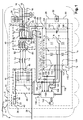
- the figure 1 represents a railway vehicle 2 supplied with electricity via a pantograph 4 which rubs on a catenary 6 supply.
- the catenary 6 is supplied with high voltage, that is to say typically a DC voltage with a nominal value greater than or equal to 600 Vdc.
- the supply voltage of the catenary 6 is equal to 1500Vdc.
- the vehicle 2 is, for example, a metro equipped with emergency ventilation, a train or a tram.
- the vehicle 2 comprises an auxiliary converter 10 adapted to supply a three-phase medium voltage to an auxiliary network 12.
- the three-phase voltage on the bus 12 is equal to 400 Vac.
- the auxiliary network 12 comprises three phase conductors 14 to 16 and a neutral conductor 18.
- the auxiliary network 12 extends in several cars of the vehicle 2.
- the vehicle 2 comprises at least two auxiliary converters and generally at least two buses at 400 Vac.
- the set of auxiliary charges embedded in this vehicle 2 are connected to the bus 12.
- the low voltage charges continued here are not shown.
- Auxiliary loads are divided into two groups, a group of simple auxiliary loads and a group of auxiliary backup loads.
- Simple auxiliary loads are those that must be energized in normal mode and must not be energized in emergency mode.
- the normal mode is here defined as the operating mode in which the simple auxiliary charges are fed from the energy collected via the pantograph 4.
- the auxiliary auxiliary loads are also powered via the bus 12 from the energy captured through the pantograph 4 in normal mode.
- the backup mode is defined as the operating mode in which only the auxiliary backup loads are energized. In the emergency mode, these charges are only powered from an electrical energy storage device embedded in the vehicle 2.
- the emergency mode corresponds to a mode of operation of the vehicle 2 following an interruption of the power supply of the vehicle 2 from the catenary 6. Such interruption of the power supply may be of accidental origin or be caused.
- the load 20 is, for example, the air conditioning of a car.
- the load 20 is connected to the auxiliary network 12 via a controllable contactor 24.
- the switch 24 is able to electrically isolate the load 20 of the bus 12 in emergency mode.
- the load 22 is connected, without passing through contactors, to the network 12 so that it is fed both in normal mode and in emergency mode.
- the load 22 is, for example, a fan for circulating air in one of the cars of the vehicle 2 supplied with medium voltage.
- the converter 10 is here also able to supply a low voltage DC bus formed of two conductors 28 and 30 electrically isolated from each other.
- the low voltage is typically 110 Vdc.
- a rechargeable electric energy storage device 32 is electrically connected between the conductors 28 and 30.
- the rechargeable energy storage device 32 comprises two output terminals.
- the device 32 is able to store enough energy to allow to feed alone the backup auxiliary loads for more than thirty minutes.
- the device 32 is a battery.
- the converter 10 is connected via conductors 36 and 38 electrically insulated from each other.
- the circuit 40 comprises a switch or contactor 50 connected in series with the conductor 36 so as to isolate the converter when the switch 50 is open and, alternately, to connect the converter to its power supply when the switch 50 is closed.
- the converter 10 is connected via the conductors 36 and 38 to a forced-switching single-phase bridge (PMCF) supplied by the catenary via a transformer.
- PMCF forced-switching single-phase bridge
- the circuit 40 also comprises, connected in parallel with the switch 50, a controllable switch or contactor 52 connected in series with a pre-charge resistor 54.
- the precharging circuits are known and the circuit 40 will therefore not be described here in more detail.
- the filter 42 is an LC filter comprising an inductance L connected in series on the conductor 36 and a capacitor C f connected between the conductor 36 and the conductor 38.
- the inverter 44 is able to transform the DC voltage filtered by the filter 42 into a three-phase voltage of frequency f T.
- the frequency f T is between 45 Hz and 65 Hz.
- the frequency f T is equal to 50 Hz.
- Each of the phases of the three-phase voltage produced is delivered by a respective terminal 58 to 60.
- the sinusoidal output filter makes it possible to filter the three-phase voltage produced by the inverter 44 on the terminals 58 to 60.
- the sinusoidal output filter is formed of three inductances L 1 , L 2 and L 3 connected by one end, respectively at the terminals 58 to 60 and at the other end to respective output terminals 62 to 64 of the filter 46.
- the inductors L1, L2, L3 are integrated as leakage inductances of the transformer.
- the terminals 62, 63 and 64 are connected to a respective end of three primary windings 70 to 72 of the transformer 48.
- the primary windings 70 to 72 are connected in a triangle and form a set of primary windings.
- These primary windings 70 to 72 are electromagnetically coupled to three secondary windings 74 to 76 forming a set of star-connected secondary windings.
- the ends of the windings 74 to 76 which are not connected to the midpoint of the star are connected, respectively, to the output terminals 78 and 80 of the three-phase medium voltage.
- the midpoint of the star connection of the secondary windings is connected to an output terminal 82.
- Capacitors C 1 , C 2 and C 3 are respectively connected between terminals 78 and 79, 79 and 80, and 78 and 80.
- the ratio of the number of turns between the primary and secondary windings is chosen so as to deliver a three-phase average voltage across terminals 78 to 80.
- Terminals 78 to 80 and terminal 82 are respectively connected to conductors 14 to 16 and 18.
- the transformer 48 thus makes it possible to supply the auxiliary network 12 with medium voltage.
- Transformer 48 also includes three tertiary windings 84-86 electromagnetically coupled to primary windings 70-72 and secondary windings 74-76 forming a tertiary winding assembly. One end of the tertiary windings is connected to a midpoint so as to form a star connection. The other end of these tertiary windings is connected to output terminals, respectively, 88 to 90.
- the converter 2 also includes a battery charger 100.
- This charger 100 comprises three input terminals 102 to 104 connected respectively to terminals 88 to 90.
- the charger 100 also includes two terminals 106 and 108 respectively associated with the terminals of the recharging device 32 electrically connected to the conductors 28 and 30.
- auxiliary loads not shown can also be connected to the output of the battery charger and in parallel thereof.
- the charging current of the battery 32 is also measured by means of a current sensor.
- the charger 100 is reversible, i.e. it is capable of transferring electrical power from the input terminals 102 to 104 to the output terminals 106 and 108 to recharge the device 32 but also in the opposite direction so as to be able to feed the auxiliary emergency loads from the device 32.
- the charger 100 comprises for this purpose, a reversible rectifier 110 comprising three arms 112 to 114 connected in parallel between the terminals 106 and 108. Each arm comprises two controllable switches I H and I B connected in series via a point middle. The midpoints of the branches 112 to 114 bear, respectively, the references 116 to 118. The midpoints 116 to 118 are respectively connected to the terminals 102 to 104.
- the switches I H and I B are bidirectional current switches when they are closed and unidirectional current when open.
- references 120, 122, 124 and 126 have been indicated once for the switches I H and I B of the arm 112.
- transistors 120 and 124 are IGBT (Insulated Gate Bipolar Transistor) transistors.
- Each of these transistors 120, 124 is able to switch from a non-on state to a on state and vice versa, in response to a command received on its gate.
- each of these transistors are connected to a control unit 130 of the rectifier 110 by means of electrical connections represented diagrammatically by a double arrow 132.
- the control unit 130 or central unit is able to control the rectifier 110 as well as synchronously the inverter 44.
- the control unit 130 allows the rectifier 110 to operate as a rectifier in normal mode and, alternately, operates as an inverter in emergency mode.
- the central unit 130 is connected to current sensors 134 to 136 capable of measuring the intensity of the currents I R , I S , I T flowing, respectively, through the terminals 104 to 102.
- L unit 130 is also connected to two sensors 138, 140, respectively, voltages V RT and V RS .
- the voltages V RT and V RS are the voltages, respectively, between the terminals 104 and 102 and 104 and 103.
- the unit 130 is described in more detail with regard to the figure 2 .
- the unit 130 is connected to a memory 142 containing the values, in normal mode, for setpoints I dcsg of active power and I qcsg of reactive power. In normal mode, the value of the setpoint I dcsg is negative. For example, it is the same for the value of the setpoint I qcsg .
- emergency mode there is no active and reactive power control.
- the unit 130 regulates the voltage and the frequency of the bus 12 to predetermined values entered in the memory 142 (for example: 250V and 35 Hz). The role of these instructions will appear more clearly on reading the rest of this description.
- the charger 100 also includes a capacitor 150 connected between the terminals 106 and 108.
- the capacitance of this capacitor 152 is less than 50 mF. More precisely, the capacitance of this capacitor 150 is chosen so that the voltage ripple at its terminals is of the order of 1%.
- This unit 130 comprises a demodulator 160 able to establish the intensity of the active current I d and the intensity of the reactive current I q , from the measurements of the currents I R , I S and I T made by the sensors 134 to 136 and V RS and V RT voltages made by the sensors 138 and 140 in the case of operation in normal mode.
- the active currents I d and reactive I q are, respectively, equal to Icos ⁇ lsin ⁇ .
- the rms value U is substantially constant, so that the intensities of the currents I d and I q can be considered to be representative in themselves, respectively, of the active power and the reactive power.
- the demodulator 160 sends the values of the currents I d and I q to a negative input, respectively, of the subtracters 162 and 164.
- a positive input of the subtracter 162 is designed to receive the value of the setpoint I dcsg .
- An output of the subtracter 162 is connected to a regulator 166 for transmitting thereto the difference between the setpoint I dcsg and the measured current intensity I d .
- the regulator 166 is able to calculate from this difference the abscissa V d of a vector U ⁇ csg , of voltage to be generated.
- the positive input of the subtracter 164 is designed to receive the value of the setpoint I qcsg stored in the memory 142.
- An output of the subtractor 164 delivers to a regulator 168 the difference between the value of the setpoint I qcsg and the measured intensity of the current I q . From this difference, the regulator 168 is able to calculate the ordinate V q of the vector U ⁇ csg , voltage to be generated.
- the demodulator 160 is also capable of delivering an angle ⁇ corresponding to the angle between a vector U ⁇ m and the axis ⁇ of a reference ⁇ .
- the unit 130 includes a conversion block 170 for calculating the modulus M and the angle ⁇ of the vector U ⁇ csg , from the abscissa and ordinate V d and V q .
- a subtractor 172 makes it possible to calculate the difference ⁇ between the angle ⁇ and an angle ⁇ delivered by a modulator 174 of pulse width.
- the subtracter 172 is capable of delivering to a phase-locked loop 176 (better known by the acronym PLL (Phase Locked Loop)) the difference ⁇ to which the value of the angle ⁇ has been added. From the sum the angle ⁇ and the difference ⁇ , the loop 176 is capable of generating a desired frequency f s.
- PLL Phase Locked Loop
- the modulator 174 is adapted from the module M and the frequency f s to determine the times at which the different transistors must be switched and to control the switching of these transistors at the determined times. For this purpose, for example, the modulator 174 uses the intersections of a carrier with a modulator. The frequency of the carrier sets the switching frequency of the transistors.
- the vehicle 2 operates in normal mode during a phase 180.
- the vehicle 2 is fed via the pantograph 4 and the catenary 6.
- the switch 50 is in the while the switch 52 serving only to preload the input filter, once the filter is loaded, is controlled open.
- the simple auxiliary charges are electrically connected to the bus 12 so that they can be powered from it.
- the inverter 44 produces on the terminals 58 to 60 a three-phase voltage from the DC voltage present between the conductors 36 and 38.
- the transformer 48 transforms the three-phase voltage produced by the inverter 44 into a three-phase medium voltage delivered on the auxiliary bus 12.
- auxiliary loads connected to the bus 12 are thus fed from the energy picked up by the pantograph 4.
- the loads 20 and 22 are powered and operate.
- the transformer 48 also delivers three-phase voltage to the input terminals 102 to 104 of the charger 100.
- a step 192 from the three-phase voltage present on input terminals 102 to 104, the charger 100 reloads the device 32.
- the charger 100 rectifies the three-phase voltage present on the terminals 102 to 104 to to produce a DC voltage rectified between terminals 106 and 108, thereby recharging device 32.
- the sensors 134 to 136, 138 and 140 measure the voltages V RS , V RT and the currents currents I R , I S and I T.
- the values of the instructions I dcsg and I qcsg corresponding to the normal mode of operation are calculated by the regulator 130 so as to respect a law of charge of the battery. These values are negative, which corresponds to a transfer of energy via the reversible rectifier 110 going from the input terminals 102 to 104 to the output terminals 106 and 108.
- the setpoint I qcsg is zero to not consume reactive power.
- the demodulator 160 determines from the measurements made during the step 194, the coordinates V a and V b of a vector U ⁇ m of tension in the frame ⁇ .
- the Concordia transform is used.
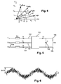
- This vector U ⁇ m is represented in the reference ⁇ of the figure 4 .
- This vector U ⁇ m makes an angle ⁇ with the axis ⁇ .
- a vector I ⁇ m corresponding to the measured three-phase current expressed in the reference ⁇ has also been represented.
- the coordinates of this vector I ⁇ m are respectively denoted I a and I b .
- These coordinates are, for example, calculated again using the Concordia transform.
- the value of the angle ⁇ is established from the coordinates V a and V b .
- the regulator 168 calculates the value of the coordinate V q from the difference ⁇ I q .
- K pq and K iq of the relation (9) do not necessarily have the same values as those of the relation (8), K pd and K id .
- the module 170 calculates the angle ⁇ and the module M of the vector U ⁇ csg , in the frame ⁇ from the coordinates V d and V q .
- the module M is transmitted directly to the modulator 174 while the angle ⁇ is transmitted to the subtracter 172.
- the angle ⁇ is a digital datum produced by the modulator 174.
- ⁇ represents the difference between the measured phase of the three-phase voltage and the phase of the three-phase voltage produced or absorbed by the rectifier 110 at the same instant.
- this difference ⁇ must be zero.
- the modulator 174 determines the switching times of the transistors 120 and 124 so as to produce a three-phase voltage of frequency f s whose effective value is equal to the module M.
- the modulator 174 also controls the switching of the transistors 120 and 124 at the determined times.
- the operations 194 and 210 are constantly repeated so that the battery 32 is recharged using a direct current from rectifying the alternating current.
- the set of transistors 120 to 124 continues to switch in a step 214 by ensuring a zero current in the battery and the supply of all the auxiliary charges connected in parallel on the battery.
- phase 180 is terminated and a phase 216 of emergency mode operation is switched to.
- Phase 216 is identical to phase 180 except that step 182 is replaced by step 218 and steps 184 and 214 are omitted.
- step 218 the simple auxiliary loads are disconnected from the auxiliary bus 12.
- the switch 24 is open to electrically isolate the load 20 from the auxiliary network 12.
- the set of auxiliary auxiliary loads remains electrically connected to the bus 12.
- the switches 50 and 52 are also open.
- steps 186 to 192 that are performed after step 218 have been represented by a dashed line.
- step 192 the energy transfer is no longer carried out from the terminals 102 to 104 to the terminals 106 to 108, but in the opposite direction, which makes it possible to supply the bus 12 from the stored energy. in the device 32.
- step 186 the load 22 is fed from the device 32 and through the electromagnetic coupling between the secondary and tertiary windings so that it continues to operate even if the Vehicle 2 is no longer powered via catenary 6.
- the figure 5 represents a model of the power part of the charger 100.
- the block R, L corresponds to a resistor and an inductance connected in series. This inductance and this resistance are incorporated in the tertiary windings 84 to 86 of the transformer 48 and have therefore not been represented on the figure 1 .
- the figure 6 represents the evolution as a function of time of the current flowing through one of the input terminals 102 to 104 when the device 32 is recharged.
- the maximum peak intensity is equal to 841 A.
- the figure 7 represents the spectrum of the curve represented on the figure 6 . It can be seen that the fundamental frequency of this phase is equal to 50 Hz. The harmonic of the nearest fundamental frequency is in the immediate vicinity of 1050 Hz (the switching frequency). In addition, the amplitude of the fundamental is at least four times greater than the amplitude of the first harmonic. Here, the amplitude of the fundamental is of 454 A.
- the figure 8 represents the evolution as a function of time of the output voltage of the charger 100 when the device 32 is recharged.
- the maximum peak amplitude is 43.7 Vdc, which represents a ripple rate of less than 37%.
- the figure 9 represents the spectrum of the charger output voltage shown on the figure 8 which includes a continuous component.
- the first significant harmonic of 50 Hz is rejected beyond 1050 Hz.
- the amplitude of the DC component not represented on the figure 9 is also greater than at least four times the amplitude of the first harmonic.
- the figure 10 represents the evolution as a function of time of the intensity of the current flowing through one of the terminals 102 to 104.
- the maximum peak intensity is equal to 575 A.
- the figure 11 represents the spectrum of the current represented on the figure 10 .
- the scale used for the figure 11 is the same as the one used for the figure 7 .
- the fundamental is located at 50 Hz.
- the first harmonic is located above 3450 Hz.
- the amplitude of the fundamental is at least ten times greater than the amplitude of the first harmonic.
- the figure 12 represents the rectified DC voltage produced by the charger 100 when the device 32 is loaded.
- the largest peak amplitude here is 11.9 Vdc, which represents a ripple rate of less than 10%.
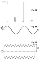
- the figure 13 represents the spectrum of the rectified DC voltage of the figure 12 which comprises a DC component located at 0 Hz and not shown.
- the first significant harmonic of 50 Hz is pushed back to more than 3450 Hz of the fundamental one.
- the amplitude of the DC component is at least five times greater than the amplitude of the first harmonic.
- Figures 14 and 15 were obtained with a frequency of 15150 Hz for the carrier of the pulse width modulation.
- the figure 14 represents the intensity of the current flowing through one of the terminals 102 to 104.
- the maximum peak intensity is 484.2 A.
- the first harmonic is pushed back to more than 15150 Hz of the fundamental frequency.
- the figure 15 represents the outer envelope of the variations of the rectified DC voltage produced by the charger 100 when it loads the device 32.
- the maximum peak amplitude is equal to 2.55 Vdc, which corresponds to a ripple rate of less than 3 %.
- the first harmonic is pushed back to more than 15150 Hz of the fundamental.
- the higher the carrier frequency of the pulse width modulation i.e. the higher the switching frequency, the more the first harmonic is rejected far from the fundamental.
- the value of the transformer dispersion inductance and the capacitance of the capacitor 152 can be reduced, which results in a reduction in the bulk of these components and in particular the filter 150. .
- the charger 100 may be connected to the conductors 14, 15 and 16 via a three-phase transformer independent of the transformer 48.
- the tertiary windings of the transformer 48 may be omitted.
- the control of the battery charger 110 described herein is a vector control.
- a scalar control can be used instead of the vector control from the moment when the switching frequency of the transistors remains at least twenty times greater than the fundamental frequency of the three-phase voltage.
- the railway vehicles comprise at least one second auxiliary converter identical, for example, to the converter 10.
- the auxiliary emergency loads are fed via a low-voltage DC bus connected to the terminals of the device 32 and not via the three-phase auxiliary bus 12.
- the capacitor bank C1, C2, C3 can be broken down into two parts with a portion that is eliminated in order to be able to supply the reactive power during normal operation and to compensate the magnetising current of the transformer in emergency mode.
- the precharge of the capacitor can be performed from the battery (deletion of the preloading device 52,54).
- the switching frequency be greater than at least twenty times the fundamental frequency of the three-phase voltage.
- the size and the mass of the filter 150 are not necessarily diminished but, on the other hand, the advantage of having a single and same reversible rectifier for exchanging electrical energy in both directions between the auxiliary loads and the device 32.
Landscapes
- Engineering & Computer Science (AREA)
- Power Engineering (AREA)
- Transportation (AREA)
- Mechanical Engineering (AREA)
- Life Sciences & Earth Sciences (AREA)
- Sustainable Development (AREA)
- Sustainable Energy (AREA)
- Business, Economics & Management (AREA)
- Emergency Management (AREA)
- Charge And Discharge Circuits For Batteries Or The Like (AREA)
- Stand-By Power Supply Arrangements (AREA)
Applications Claiming Priority (1)
| Application Number | Priority Date | Filing Date | Title |
|---|---|---|---|
| FR0756933A FR2919768B1 (fr) | 2007-08-03 | 2007-08-03 | Procede d'alimentation de charges auxiliaires de secours, convertisseur auxiliaire et vehicule ferroviaire pour ce procede. |
Publications (3)
| Publication Number | Publication Date |
|---|---|
| EP2020726A2 true EP2020726A2 (de) | 2009-02-04 |
| EP2020726A3 EP2020726A3 (de) | 2009-12-16 |
| EP2020726B1 EP2020726B1 (de) | 2016-03-30 |
Family
ID=39473979
Family Applications (1)
| Application Number | Title | Priority Date | Filing Date |
|---|---|---|---|
| EP08161463.8A Active EP2020726B1 (de) | 2007-08-03 | 2008-07-30 | Verfahren zur Einspeisung von Notfall-Hilfsladungen, Hilfswandler und Schienenfahrzeug für dieses Verfahren |
Country Status (9)
| Country | Link |
|---|---|
| EP (1) | EP2020726B1 (de) |
| KR (1) | KR101540018B1 (de) |
| CN (1) | CN101369735B (de) |
| CA (1) | CA2638224C (de) |
| DK (1) | DK2020726T3 (de) |
| ES (1) | ES2579203T3 (de) |
| FR (1) | FR2919768B1 (de) |
| HU (1) | HUE029208T2 (de) |
| RU (1) | RU2467891C2 (de) |
Cited By (12)
| Publication number | Priority date | Publication date | Assignee | Title |
|---|---|---|---|---|
| CN102299643A (zh) * | 2011-05-30 | 2011-12-28 | 山西太钢不锈钢股份有限公司 | 一种小容量电压型变频器的充电方法 |
| CN105083036A (zh) * | 2014-05-12 | 2015-11-25 | 中国北车集团大同电力机车有限责任公司 | 实现天窗期动车的系统及方法 |
| EP2802056A4 (de) * | 2011-12-31 | 2016-01-06 | Shenzhen Byd Auto R&D Co Ltd | System zum laden eines elektrischen kraftfahrzeugs und elektrisches kraftfahrzeug damit |
| CN105406569A (zh) * | 2015-12-25 | 2016-03-16 | 谢镕安 | 超级电容纯电动汽车智能充电系统 |
| EP3308996A1 (de) * | 2016-10-11 | 2018-04-18 | ALSTOM Transport Technologies | Hilfsumrichter für ein schienenfahrzeug |
| WO2018234226A1 (en) * | 2017-06-19 | 2018-12-27 | Tridonic Gmbh & Co Kg | EMERGENCY CONVERTER OUTPUT SWITCH |
| CN109450285A (zh) * | 2018-11-01 | 2019-03-08 | 北京交通大学 | 轨道交通车辆主辅一体化模式能量双向流动辅助供电系统 |
| FR3082790A1 (fr) * | 2018-06-26 | 2019-12-27 | Sncf Mobilites | Procede de regulation de la puissance electrique instantanee fournie a un vehicule ferroviaire par une source externe |
| CN113270941A (zh) * | 2021-05-28 | 2021-08-17 | 广东电网有限责任公司 | 低压交直流配电模态转换系统及其时序控制方法和装置 |
| CN116198323A (zh) * | 2021-11-30 | 2023-06-02 | 比亚迪股份有限公司 | 车辆及其供电方法 |
| CN116470643A (zh) * | 2023-04-24 | 2023-07-21 | 北京城建设计发展集团股份有限公司 | 一种轨道交通电动机负荷远距离配电系统 |
| EP4717499A1 (de) | 2024-09-27 | 2026-04-01 | ALSTOM Holdings | Mittelfrequenzhilfswandler und zugehöriges schienenfahrzeug |
Families Citing this family (18)
| Publication number | Priority date | Publication date | Assignee | Title |
|---|---|---|---|---|
| CN103190057A (zh) * | 2011-10-27 | 2013-07-03 | 丰田自动车株式会社 | 电力供给系统和车辆 |
| US9246411B2 (en) * | 2012-10-16 | 2016-01-26 | Rockwell Automation Technologies, Inc. | Regenerative voltage doubler rectifier, voltage sag/swell correction apparatus and operating methods |
| CN103812371A (zh) * | 2012-11-15 | 2014-05-21 | 中国北车股份有限公司 | 辅助变流器 |
| FR3004020B1 (fr) * | 2013-04-02 | 2015-05-01 | Faiveley Transp Tours | Dispositif d'interface entre un systeme d'alimentation auxiliaire et un module de generation d'energie dans un vehicule ferroviaire |
| CN106992704A (zh) * | 2017-04-20 | 2017-07-28 | 中车大连电力牵引研发中心有限公司 | 辅助变流器及辅助变流器外接系统 |
| EP3407449A1 (de) | 2017-05-24 | 2018-11-28 | Siemens Aktiengesellschaft | Redundantes gleichspannungsnetz |
| DE102017218455A1 (de) * | 2017-10-16 | 2019-04-18 | Siemens Mobility GmbH | Energiespeicheranordnung und Verfahren zum Betreiben einer solchen Energiespeicheranordnung |
| SE541627C2 (en) * | 2018-03-20 | 2019-11-19 | Bombardier Transp Gmbh | A system and a method for feeding electric power to a consumer thereof |
| JP6710239B2 (ja) * | 2018-05-25 | 2020-06-17 | 本田技研工業株式会社 | 車両の電源システム |
| CN109941108B (zh) * | 2019-04-02 | 2021-11-12 | 中车株洲电力机车有限公司 | 轨道交通车辆及其故障保护方法 |
| CN111969855B (zh) * | 2019-11-01 | 2024-05-14 | 西安爱科赛博电气股份有限公司 | 导轨电力机车辅助供电装置、导轨电力机车及其供电方法 |
| CN112124152B (zh) * | 2020-09-22 | 2021-12-17 | 中车株洲电力机车有限公司 | 一种机车辅助系统供电电路及供电控制方法 |
| CN112238763B (zh) * | 2020-10-23 | 2022-05-13 | 中车株洲电力机车有限公司 | 一种充电电路及其控制装置、控制方法 |
| CN112498181B (zh) * | 2020-12-16 | 2024-08-13 | 中车大连机车车辆有限公司 | 车辆分段连续式地面供电系统供电模块 |
| CN113799663B (zh) * | 2021-11-19 | 2022-03-04 | 西南交通大学 | 一种动车供电传动系统、交直交牵引变流器及其控制方法 |
| CN114117976A (zh) * | 2021-11-26 | 2022-03-01 | 合肥美的暖通设备有限公司 | 空调设备及其输入参数估算方法、电路和存储介质 |
| CN116811641B (zh) * | 2023-06-29 | 2025-11-28 | 龙岩市民富电力设备有限公司 | 一种根据变压器冗余容量确定投入充电桩的方法 |
| CN116691426B (zh) * | 2023-08-02 | 2023-10-10 | 山东同云新能源科技有限公司 | 一种充电机器人的控制方法和系统 |
Family Cites Families (10)
| Publication number | Priority date | Publication date | Assignee | Title |
|---|---|---|---|---|
| SU1611767A1 (ru) * | 1989-01-26 | 1990-12-07 | Воронежское Проектно-Конструкторское Бюро Производственного Объединения "Росремэлектротранс" | Устройство дл электроснабжени вспомогательного оборудовани транспортного средства |
| AU639914B2 (en) * | 1989-04-04 | 1993-08-12 | Anthony Joseph Griffin | Voltage regulation/conversion device and method |
| EP0607011B1 (de) * | 1993-01-12 | 1998-07-15 | Kabushiki Kaisha Toshiba | Steuereinrichtung für Wechselrichterverbindungssystem |
| RU6752U1 (ru) * | 1997-06-10 | 1998-06-16 | Товарищество с ограниченной ответственностью - Научно-производственный центр "Экспресс" | Система электроснабжения пассажирского вагона |
| RU2166439C2 (ru) * | 1999-04-08 | 2001-05-10 | Лиманский Сергей Сергеевич | Устройство для электропитания низковольтных цепей городского электротранспорта |
| RU29692U1 (ru) * | 2002-05-30 | 2003-05-27 | Григорьев Эдуард Николаевич | Комплекс электроснабжения пассажирского вагона |
| WO2004054065A1 (en) * | 2002-12-06 | 2004-06-24 | Electric Power Research Institute, Inc. | Uninterruptable power supply and generator system |
| GB2405754A (en) * | 2003-09-03 | 2005-03-09 | Bombardier Transp Gmbh | Converter input detection signal filtering |
| EP1766750A1 (de) * | 2004-07-08 | 2007-03-28 | LV Power (2003) Ltd. | System zur bidirektionalen energiewandlung |
| RU63620U1 (ru) * | 2006-12-12 | 2007-05-27 | Открытое акционерное общество "Всероссийский научно-исследовательский и проектно-конструкторский институт электровозостроения" (ОАО "ВЭлНИИ") | Преобразователь постоянного напряжения |
-
2007
- 2007-08-03 FR FR0756933A patent/FR2919768B1/fr not_active Expired - Fee Related
-
2008
- 2008-07-30 HU HUE08161463A patent/HUE029208T2/en unknown
- 2008-07-30 ES ES08161463.8T patent/ES2579203T3/es active Active
- 2008-07-30 EP EP08161463.8A patent/EP2020726B1/de active Active
- 2008-07-30 DK DK08161463.8T patent/DK2020726T3/en active
- 2008-08-01 CA CA2638224A patent/CA2638224C/fr active Active
- 2008-08-01 CN CN2008101714499A patent/CN101369735B/zh active Active
- 2008-08-01 RU RU2008131964/11A patent/RU2467891C2/ru active
- 2008-08-04 KR KR1020080076220A patent/KR101540018B1/ko not_active Expired - Fee Related
Non-Patent Citations (1)
| Title |
|---|
| J. RODRIGUEZ, IEEE « PWM REGENERATIVE RECTIFIERS : STATE OF THE ART » |
Cited By (24)
| Publication number | Priority date | Publication date | Assignee | Title |
|---|---|---|---|---|
| CN102299643B (zh) * | 2011-05-30 | 2013-12-25 | 山西太钢不锈钢股份有限公司 | 一种小容量电压型变频器的充电方法 |
| CN102299643A (zh) * | 2011-05-30 | 2011-12-28 | 山西太钢不锈钢股份有限公司 | 一种小容量电压型变频器的充电方法 |
| US10173545B2 (en) | 2011-12-31 | 2019-01-08 | Byd Company Limited | Electric vehicle and discharging apparatus thereof |
| EP2802056A4 (de) * | 2011-12-31 | 2016-01-06 | Shenzhen Byd Auto R&D Co Ltd | System zum laden eines elektrischen kraftfahrzeugs und elektrisches kraftfahrzeug damit |
| US9493088B2 (en) | 2011-12-31 | 2016-11-15 | Shenzhen Byd Auto R&D Company Limited | Electric automobile and integrated control system thereof |
| US9604545B2 (en) | 2011-12-31 | 2017-03-28 | Shenzhen Byd Auto R&D Company Limited | Carrier communication method and system based on charging-discharging of electric vehicle and carrier device |
| US9718373B2 (en) | 2011-12-31 | 2017-08-01 | Shenzhen Byd R&D Company Limited | Electric vehicle and discharging apparatus thereof |
| US9718374B2 (en) | 2011-12-31 | 2017-08-01 | Shenzhen Byd Auto R&D Company Limited | Electric vehicle and charging system for electric vehicle |
| US9796287B2 (en) | 2011-12-31 | 2017-10-24 | Shenzhen Byd Auto R&D Company Limited | Electric vehicle and discharging apparatus thereof |
| US9969290B2 (en) | 2011-12-31 | 2018-05-15 | Shenzhen Byd Auto R&D Company Limited | Charging system for electric vehicle and electric vehicle comprising the same |
| CN105083036A (zh) * | 2014-05-12 | 2015-11-25 | 中国北车集团大同电力机车有限责任公司 | 实现天窗期动车的系统及方法 |
| CN105406569A (zh) * | 2015-12-25 | 2016-03-16 | 谢镕安 | 超级电容纯电动汽车智能充电系统 |
| EP3308996B1 (de) | 2016-10-11 | 2021-12-01 | ALSTOM Transport Technologies | Hilfsumrichter für ein schienenfahrzeug |
| EP3308996A1 (de) * | 2016-10-11 | 2018-04-18 | ALSTOM Transport Technologies | Hilfsumrichter für ein schienenfahrzeug |
| WO2018234226A1 (en) * | 2017-06-19 | 2018-12-27 | Tridonic Gmbh & Co Kg | EMERGENCY CONVERTER OUTPUT SWITCH |
| FR3082790A1 (fr) * | 2018-06-26 | 2019-12-27 | Sncf Mobilites | Procede de regulation de la puissance electrique instantanee fournie a un vehicule ferroviaire par une source externe |
| EP3594047A1 (de) * | 2018-06-26 | 2020-01-15 | SNCF Mobilités | Regulierungsverfahren der elektrischen sofortleistung, die einem schienenfahrzeug von einer externen quelle geliefert wird |
| CN109450285A (zh) * | 2018-11-01 | 2019-03-08 | 北京交通大学 | 轨道交通车辆主辅一体化模式能量双向流动辅助供电系统 |
| CN109450285B (zh) * | 2018-11-01 | 2023-10-31 | 北京交通大学 | 轨道交通车辆主辅一体化模式能量双向流动辅助供电系统 |
| CN113270941A (zh) * | 2021-05-28 | 2021-08-17 | 广东电网有限责任公司 | 低压交直流配电模态转换系统及其时序控制方法和装置 |
| CN113270941B (zh) * | 2021-05-28 | 2022-08-12 | 广东电网有限责任公司 | 低压交直流配电模态转换系统及其时序控制方法和装置 |
| CN116198323A (zh) * | 2021-11-30 | 2023-06-02 | 比亚迪股份有限公司 | 车辆及其供电方法 |
| CN116470643A (zh) * | 2023-04-24 | 2023-07-21 | 北京城建设计发展集团股份有限公司 | 一种轨道交通电动机负荷远距离配电系统 |
| EP4717499A1 (de) | 2024-09-27 | 2026-04-01 | ALSTOM Holdings | Mittelfrequenzhilfswandler und zugehöriges schienenfahrzeug |
Also Published As
| Publication number | Publication date |
|---|---|
| KR20090014127A (ko) | 2009-02-06 |
| FR2919768B1 (fr) | 2016-02-12 |
| EP2020726B1 (de) | 2016-03-30 |
| HUE029208T2 (en) | 2017-02-28 |
| CA2638224A1 (fr) | 2009-02-03 |
| KR101540018B1 (ko) | 2015-08-06 |
| FR2919768A1 (fr) | 2009-02-06 |
| RU2008131964A (ru) | 2010-02-10 |
| ES2579203T3 (es) | 2016-08-08 |
| CA2638224C (fr) | 2016-03-01 |
| EP2020726A3 (de) | 2009-12-16 |
| CN101369735A (zh) | 2009-02-18 |
| DK2020726T3 (en) | 2016-06-27 |
| RU2467891C2 (ru) | 2012-11-27 |
| CN101369735B (zh) | 2013-04-17 |
Similar Documents
| Publication | Publication Date | Title |
|---|---|---|
| EP2020726B1 (de) | Verfahren zur Einspeisung von Notfall-Hilfsladungen, Hilfswandler und Schienenfahrzeug für dieses Verfahren | |
| EP2732530B1 (de) | Schnelles mehrstufiges wiederaufladesystem | |
| EP2367704B1 (de) | Kombinierte elektrische vorrichtung zum antreiben und laden | |
| KR101628592B1 (ko) | 전기차의 추진 제어 장치 및 그 제어 방법 | |
| EP3045343B1 (de) | Wandler für eine elektrische zuleitung und/oder substation zur rückgewinnung der bremsenergie | |
| EP3554887A1 (de) | Verfahren zur steuerung einer aufladevorrichtung an bord eines elektro- oder hybridfahrzeugs | |
| EP3776798A1 (de) | Eingangsleistungssteuerung einer ladestation für elektrofahrzeuge | |
| EP2831977B1 (de) | Verfahren und system zur stromversorgung eines hybridkraftfahrzeugs mit zwei stromspeichern | |
| FR2738411A1 (fr) | Systeme d'alimentation electrique mixte onduleur et convertisseur alternatif-continu | |
| EP2413471A2 (de) | Aufladevorrichtung für Akkumulatoren | |
| EP3227137A1 (de) | Verbesserter gleichstromwandler und stromversorgungsvorrichtung | |
| EP3389175B1 (de) | Umwandlungsvorrichtung, entsprechendes steuerverfahren und entsprechendes fahrzeug | |
| EP3707815B1 (de) | Verfahren zur steuerung eines dreiphasigen vienna-gleichrichters bei fehlerhaftem leistungsschalter | |
| EP3539204B1 (de) | Verfahren zur steuerung eines dreiphasigen gleichrichters für eine ladevorrichtung an bord eines elektro- oder hybridfahrzeugs | |
| FR2987946A1 (fr) | Procede de decharge d'au moins un condensateur d'un circuit electrique | |
| FR3026243A1 (fr) | Dispositif et procede de charge d'une batterie et d'alimentation d'une machine electrique a double convertisseur continu-continu | |
| FR3025057A1 (fr) | Chargeur de batterie pour un vehicule automobile electrique ou hybride a haute integration. | |
| EP3539203B1 (de) | Verfahren zur steuerung eines dreiphasigen wechselrichters für eine ladevorrichtung an bord eines elektro- oder hybridfahrzeugs | |
| EP2801150B1 (de) | System zur bereitstellung einer wechselstromlast aus mehreren gleichspannungsquellen | |
| EP3721543A1 (de) | Gleichspannungswandler mit vorladung eines ersten stromnetzes aus einem zweiten stromnetz | |
| FR3026242A1 (fr) | Dispositif combine de charge d'une batterie et d'alimentation electrique d'une machine electrique | |
| FR2903248A1 (fr) | Dispositif de conversion electrique,convertisseur et alimentation electrique sans interruption comportant un tel dispositif | |
| FR2932327A1 (fr) | Variateur de vitesse avec super-condensateur | |
| EP1372239A1 (de) | Konditionierer für elektrisches Netz | |
| FR2600221A1 (fr) | Alimentation en courant alternatif de forte puissance non susceptible d'etre interrompue |
Legal Events
| Date | Code | Title | Description |
|---|---|---|---|
| PUAI | Public reference made under article 153(3) epc to a published international application that has entered the european phase |
Free format text: ORIGINAL CODE: 0009012 |
|
| AK | Designated contracting states |
Kind code of ref document: A2 Designated state(s): AT BE BG CH CY CZ DE DK EE ES FI FR GB GR HR HU IE IS IT LI LT LU LV MC MT NL NO PL PT RO SE SI SK TR |
|
| AX | Request for extension of the european patent |
Extension state: AL BA MK RS |
|
| PUAL | Search report despatched |
Free format text: ORIGINAL CODE: 0009013 |
|
| AK | Designated contracting states |
Kind code of ref document: A3 Designated state(s): AT BE BG CH CY CZ DE DK EE ES FI FR GB GR HR HU IE IS IT LI LT LU LV MC MT NL NO PL PT RO SE SI SK TR |
|
| AX | Request for extension of the european patent |
Extension state: AL BA MK RS |
|
| 17P | Request for examination filed |
Effective date: 20100616 |
|
| 17Q | First examination report despatched |
Effective date: 20100707 |
|
| AKX | Designation fees paid |
Designated state(s): AT BE BG CH CY CZ DE DK EE ES FI FR GB GR HR HU IE IS IT LI LT LU LV MC MT NL NO PL PT RO SE SI SK TR |
|
| RAP1 | Party data changed (applicant data changed or rights of an application transferred) |
Owner name: ALSTOM TRANSPORT TECHNOLOGIES |
|
| GRAP | Despatch of communication of intention to grant a patent |
Free format text: ORIGINAL CODE: EPIDOSNIGR1 |
|
| RIC1 | Information provided on ipc code assigned before grant |
Ipc: B60L 1/00 20060101ALN20150902BHEP Ipc: B60L 3/00 20060101ALN20150902BHEP Ipc: H02J 9/06 20060101AFI20150902BHEP Ipc: B60L 9/00 20060101ALN20150902BHEP |
|
| INTG | Intention to grant announced |
Effective date: 20151002 |
|
| GRAS | Grant fee paid |
Free format text: ORIGINAL CODE: EPIDOSNIGR3 |
|
| GRAA | (expected) grant |
Free format text: ORIGINAL CODE: 0009210 |
|
| AK | Designated contracting states |
Kind code of ref document: B1 Designated state(s): AT BE BG CH CY CZ DE DK EE ES FI FR GB GR HR HU IE IS IT LI LT LU LV MC MT NL NO PL PT RO SE SI SK TR |
|
| REG | Reference to a national code |
Ref country code: GB Ref legal event code: FG4D Free format text: NOT ENGLISH |
|
| REG | Reference to a national code |
Ref country code: CH Ref legal event code: EP |
|
| REG | Reference to a national code |
Ref country code: AT Ref legal event code: REF Ref document number: 786335 Country of ref document: AT Kind code of ref document: T Effective date: 20160415 |
|
| REG | Reference to a national code |
Ref country code: IE Ref legal event code: FG4D Free format text: LANGUAGE OF EP DOCUMENT: FRENCH |
|
| REG | Reference to a national code |
Ref country code: DE Ref legal event code: R096 Ref document number: 602008043150 Country of ref document: DE |
|
| REG | Reference to a national code |
Ref country code: CH Ref legal event code: NV Representative=s name: ARNOLD AND SIEDSMA AG, CH |
|
| REG | Reference to a national code |
Ref country code: DE Ref legal event code: R082 Ref document number: 602008043150 Country of ref document: DE Representative=s name: LAVOIX MUNICH, DE |
|
| REG | Reference to a national code |
Ref country code: DK Ref legal event code: T3 Effective date: 20160623 Ref country code: RO Ref legal event code: EPE |
|
| REG | Reference to a national code |
Ref country code: SE Ref legal event code: TRGR |
|
| REG | Reference to a national code |
Ref country code: NL Ref legal event code: FP |
|
| REG | Reference to a national code |
Ref country code: FR Ref legal event code: PLFP Year of fee payment: 9 |
|
| REG | Reference to a national code |
Ref country code: LT Ref legal event code: MG4D |
|
| PG25 | Lapsed in a contracting state [announced via postgrant information from national office to epo] |
Ref country code: FI Free format text: LAPSE BECAUSE OF FAILURE TO SUBMIT A TRANSLATION OF THE DESCRIPTION OR TO PAY THE FEE WITHIN THE PRESCRIBED TIME-LIMIT Effective date: 20160330 Ref country code: NO Free format text: LAPSE BECAUSE OF FAILURE TO SUBMIT A TRANSLATION OF THE DESCRIPTION OR TO PAY THE FEE WITHIN THE PRESCRIBED TIME-LIMIT Effective date: 20160630 Ref country code: HR Free format text: LAPSE BECAUSE OF FAILURE TO SUBMIT A TRANSLATION OF THE DESCRIPTION OR TO PAY THE FEE WITHIN THE PRESCRIBED TIME-LIMIT Effective date: 20160330 Ref country code: GR Free format text: LAPSE BECAUSE OF FAILURE TO SUBMIT A TRANSLATION OF THE DESCRIPTION OR TO PAY THE FEE WITHIN THE PRESCRIBED TIME-LIMIT Effective date: 20160701 |
|
| REG | Reference to a national code |
Ref country code: ES Ref legal event code: FG2A Ref document number: 2579203 Country of ref document: ES Kind code of ref document: T3 Effective date: 20160808 |
|
| PG25 | Lapsed in a contracting state [announced via postgrant information from national office to epo] |
Ref country code: LV Free format text: LAPSE BECAUSE OF FAILURE TO SUBMIT A TRANSLATION OF THE DESCRIPTION OR TO PAY THE FEE WITHIN THE PRESCRIBED TIME-LIMIT Effective date: 20160330 Ref country code: LT Free format text: LAPSE BECAUSE OF FAILURE TO SUBMIT A TRANSLATION OF THE DESCRIPTION OR TO PAY THE FEE WITHIN THE PRESCRIBED TIME-LIMIT Effective date: 20160330 |
|
| RAP2 | Party data changed (patent owner data changed or rights of a patent transferred) |
Owner name: ALSTOM TRANSPORT TECHNOLOGIES |
|
| PG25 | Lapsed in a contracting state [announced via postgrant information from national office to epo] |
Ref country code: EE Free format text: LAPSE BECAUSE OF FAILURE TO SUBMIT A TRANSLATION OF THE DESCRIPTION OR TO PAY THE FEE WITHIN THE PRESCRIBED TIME-LIMIT Effective date: 20160330 Ref country code: IS Free format text: LAPSE BECAUSE OF FAILURE TO SUBMIT A TRANSLATION OF THE DESCRIPTION OR TO PAY THE FEE WITHIN THE PRESCRIBED TIME-LIMIT Effective date: 20160730 Ref country code: PL Free format text: LAPSE BECAUSE OF FAILURE TO SUBMIT A TRANSLATION OF THE DESCRIPTION OR TO PAY THE FEE WITHIN THE PRESCRIBED TIME-LIMIT Effective date: 20160330 |
|
| PG25 | Lapsed in a contracting state [announced via postgrant information from national office to epo] |
Ref country code: SK Free format text: LAPSE BECAUSE OF FAILURE TO SUBMIT A TRANSLATION OF THE DESCRIPTION OR TO PAY THE FEE WITHIN THE PRESCRIBED TIME-LIMIT Effective date: 20160330 Ref country code: CZ Free format text: LAPSE BECAUSE OF FAILURE TO SUBMIT A TRANSLATION OF THE DESCRIPTION OR TO PAY THE FEE WITHIN THE PRESCRIBED TIME-LIMIT Effective date: 20160330 Ref country code: PT Free format text: LAPSE BECAUSE OF FAILURE TO SUBMIT A TRANSLATION OF THE DESCRIPTION OR TO PAY THE FEE WITHIN THE PRESCRIBED TIME-LIMIT Effective date: 20160801 |
|
| REG | Reference to a national code |
Ref country code: DE Ref legal event code: R097 Ref document number: 602008043150 Country of ref document: DE |
|
| PLBE | No opposition filed within time limit |
Free format text: ORIGINAL CODE: 0009261 |
|
| STAA | Information on the status of an ep patent application or granted ep patent |
Free format text: STATUS: NO OPPOSITION FILED WITHIN TIME LIMIT |
|
| REG | Reference to a national code |
Ref country code: HU Ref legal event code: AG4A Ref document number: E029208 Country of ref document: HU |
|
| 26N | No opposition filed |
Effective date: 20170103 |
|
| PG25 | Lapsed in a contracting state [announced via postgrant information from national office to epo] |
Ref country code: MC Free format text: LAPSE BECAUSE OF FAILURE TO SUBMIT A TRANSLATION OF THE DESCRIPTION OR TO PAY THE FEE WITHIN THE PRESCRIBED TIME-LIMIT Effective date: 20160330 |
|
| PG25 | Lapsed in a contracting state [announced via postgrant information from national office to epo] |
Ref country code: SI Free format text: LAPSE BECAUSE OF FAILURE TO SUBMIT A TRANSLATION OF THE DESCRIPTION OR TO PAY THE FEE WITHIN THE PRESCRIBED TIME-LIMIT Effective date: 20160330 |
|
| REG | Reference to a national code |
Ref country code: HU Ref legal event code: HC9C Owner name: ALSTOM TRANSPORT TECHNOLOGIES, FR Free format text: FORMER OWNER(S): ALSTOM TRANSPORT TECHNOLOGIES, FR |
|
| REG | Reference to a national code |
Ref country code: FR Ref legal event code: PLFP Year of fee payment: 10 |
|
| PG25 | Lapsed in a contracting state [announced via postgrant information from national office to epo] |
Ref country code: LU Free format text: LAPSE BECAUSE OF NON-PAYMENT OF DUE FEES Effective date: 20160730 |
|
| REG | Reference to a national code |
Ref country code: DE Ref legal event code: R082 Ref document number: 602008043150 Country of ref document: DE Representative=s name: LAVOIX MUNICH, DE Ref country code: DE Ref legal event code: R081 Ref document number: 602008043150 Country of ref document: DE Owner name: ALSTOM TRANSPORT TECHNOLOGIES, FR Free format text: FORMER OWNER: ALSTOM TRANSPORT TECHNOLOGIES, LEVALLOIS-PERRET, FR |
|
| REG | Reference to a national code |
Ref country code: CH Ref legal event code: PCOW Free format text: NEW ADDRESS: 48 RUE ALBERT DHALENNE, 93400 SAINT-OUEN (FR) |
|
| REG | Reference to a national code |
Ref country code: FR Ref legal event code: CA Effective date: 20180103 |
|
| REG | Reference to a national code |
Ref country code: BE Ref legal event code: PD Owner name: ALSTOM TRANSPORT TECHNOLOGIES; FR Free format text: DETAILS ASSIGNMENT: CHANGE OF OWNER(S), AUTRE, ADRESSE; FORMER OWNER NAME: ALSTOM TRANSPORT TECHNOLOGIES Effective date: 20171031 |
|
| PG25 | Lapsed in a contracting state [announced via postgrant information from national office to epo] |
Ref country code: CY Free format text: LAPSE BECAUSE OF FAILURE TO SUBMIT A TRANSLATION OF THE DESCRIPTION OR TO PAY THE FEE WITHIN THE PRESCRIBED TIME-LIMIT Effective date: 20160330 |
|
| PG25 | Lapsed in a contracting state [announced via postgrant information from national office to epo] |
Ref country code: MT Free format text: LAPSE BECAUSE OF FAILURE TO SUBMIT A TRANSLATION OF THE DESCRIPTION OR TO PAY THE FEE WITHIN THE PRESCRIBED TIME-LIMIT Effective date: 20160330 Ref country code: TR Free format text: LAPSE BECAUSE OF FAILURE TO SUBMIT A TRANSLATION OF THE DESCRIPTION OR TO PAY THE FEE WITHIN THE PRESCRIBED TIME-LIMIT Effective date: 20160330 |
|
| REG | Reference to a national code |
Ref country code: FR Ref legal event code: PLFP Year of fee payment: 11 |
|
| PG25 | Lapsed in a contracting state [announced via postgrant information from national office to epo] |
Ref country code: BG Free format text: LAPSE BECAUSE OF FAILURE TO SUBMIT A TRANSLATION OF THE DESCRIPTION OR TO PAY THE FEE WITHIN THE PRESCRIBED TIME-LIMIT Effective date: 20160330 |
|
| REG | Reference to a national code |
Ref country code: AT Ref legal event code: UEP Ref document number: 786335 Country of ref document: AT Kind code of ref document: T Effective date: 20160330 |
|
| PGFP | Annual fee paid to national office [announced via postgrant information from national office to epo] |
Ref country code: AT Payment date: 20210722 Year of fee payment: 14 Ref country code: IE Payment date: 20210723 Year of fee payment: 14 |
|
| PGFP | Annual fee paid to national office [announced via postgrant information from national office to epo] |
Ref country code: DK Payment date: 20210723 Year of fee payment: 14 Ref country code: HU Payment date: 20210718 Year of fee payment: 14 Ref country code: RO Payment date: 20210723 Year of fee payment: 14 |
|
| REG | Reference to a national code |
Ref country code: DK Ref legal event code: EBP Effective date: 20220731 |
|
| REG | Reference to a national code |
Ref country code: AT Ref legal event code: MM01 Ref document number: 786335 Country of ref document: AT Kind code of ref document: T Effective date: 20220730 |
|
| PG25 | Lapsed in a contracting state [announced via postgrant information from national office to epo] |
Ref country code: RO Free format text: LAPSE BECAUSE OF NON-PAYMENT OF DUE FEES Effective date: 20220730 Ref country code: AT Free format text: LAPSE BECAUSE OF NON-PAYMENT OF DUE FEES Effective date: 20220730 |
|
| PG25 | Lapsed in a contracting state [announced via postgrant information from national office to epo] |
Ref country code: HU Free format text: LAPSE BECAUSE OF NON-PAYMENT OF DUE FEES Effective date: 20220731 |
|
| PG25 | Lapsed in a contracting state [announced via postgrant information from national office to epo] |
Ref country code: IE Free format text: LAPSE BECAUSE OF NON-PAYMENT OF DUE FEES Effective date: 20220730 Ref country code: DK Free format text: LAPSE BECAUSE OF NON-PAYMENT OF DUE FEES Effective date: 20220731 |
|
| P01 | Opt-out of the competence of the unified patent court (upc) registered |
Effective date: 20230823 |
|
| REG | Reference to a national code |
Ref country code: GB Ref legal event code: 732E Free format text: REGISTERED BETWEEN 20250213 AND 20250219 |
|
| REG | Reference to a national code |
Ref country code: ES Ref legal event code: PC2A Owner name: ALSTOM HOLDINGS Effective date: 20250310 |
|
| REG | Reference to a national code |
Ref country code: BE Ref legal event code: PD Owner name: ALSTOM HOLDINGS; FR Free format text: DETAILS ASSIGNMENT: CHANGE OF OWNER(S), ASSIGNMENT; FORMER OWNER NAME: ALSTOM TRANSPORT TECHNOLOGIES Effective date: 20241025 |
|
| PGFP | Annual fee paid to national office [announced via postgrant information from national office to epo] |
Ref country code: NL Payment date: 20250721 Year of fee payment: 18 |
|
| PGFP | Annual fee paid to national office [announced via postgrant information from national office to epo] |
Ref country code: ES Payment date: 20250826 Year of fee payment: 18 |
|
| PGFP | Annual fee paid to national office [announced via postgrant information from national office to epo] |
Ref country code: DE Payment date: 20250722 Year of fee payment: 18 |
|
| PGFP | Annual fee paid to national office [announced via postgrant information from national office to epo] |
Ref country code: IT Payment date: 20250724 Year of fee payment: 18 |
|
| PGFP | Annual fee paid to national office [announced via postgrant information from national office to epo] |
Ref country code: BE Payment date: 20250721 Year of fee payment: 18 Ref country code: GB Payment date: 20250722 Year of fee payment: 18 |
|
| PGFP | Annual fee paid to national office [announced via postgrant information from national office to epo] |
Ref country code: FR Payment date: 20250724 Year of fee payment: 18 |
|
| PGFP | Annual fee paid to national office [announced via postgrant information from national office to epo] |
Ref country code: CH Payment date: 20250801 Year of fee payment: 18 Ref country code: SE Payment date: 20250722 Year of fee payment: 18 |