EP2020732A1 - Noyau pour élément inducteur - Google Patents
Noyau pour élément inducteur Download PDFInfo
- Publication number
- EP2020732A1 EP2020732A1 EP07743821A EP07743821A EP2020732A1 EP 2020732 A1 EP2020732 A1 EP 2020732A1 EP 07743821 A EP07743821 A EP 07743821A EP 07743821 A EP07743821 A EP 07743821A EP 2020732 A1 EP2020732 A1 EP 2020732A1
- Authority
- EP
- European Patent Office
- Prior art keywords
- connecting portion
- element core
- field element
- curved
- seen
- Prior art date
- Legal status (The legal status is an assumption and is not a legal conclusion. Google has not performed a legal analysis and makes no representation as to the accuracy of the status listed.)
- Granted
Links
Images








Classifications
-
- H—ELECTRICITY
- H02—GENERATION; CONVERSION OR DISTRIBUTION OF ELECTRIC POWER
- H02K—DYNAMO-ELECTRIC MACHINES
- H02K1/00—Details of the magnetic circuit
- H02K1/06—Details of the magnetic circuit characterised by the shape, form or construction
- H02K1/22—Rotating parts of the magnetic circuit
-
- H—ELECTRICITY
- H02—GENERATION; CONVERSION OR DISTRIBUTION OF ELECTRIC POWER
- H02K—DYNAMO-ELECTRIC MACHINES
- H02K1/00—Details of the magnetic circuit
- H02K1/06—Details of the magnetic circuit characterised by the shape, form or construction
- H02K1/22—Rotating parts of the magnetic circuit
- H02K1/27—Rotor cores with permanent magnets
- H02K1/2706—Inner rotors
- H02K1/272—Inner rotors the magnetisation axis of the magnets being perpendicular to the rotor axis
- H02K1/274—Inner rotors the magnetisation axis of the magnets being perpendicular to the rotor axis the rotor consisting of two or more circumferentially positioned magnets
- H02K1/2753—Inner rotors the magnetisation axis of the magnets being perpendicular to the rotor axis the rotor consisting of two or more circumferentially positioned magnets the rotor consisting of magnets or groups of magnets arranged with alternating polarity
- H02K1/276—Magnets embedded in the magnetic core, e.g. interior permanent magnets [IPM]
Definitions
- the present invention relates to a core for a field element, and particularly to the configuration of the field element core.
- Patent Document 1 discloses a technique in which a slot for insertion of a field magnet is divided into two, and a connecting portion (which is referred to as "a bridge" in Patent Document 1) which connects the outer side and the inner side of the field element core across the slots is provided.
- the divided slots of Patent Document 1 are rectangular-shaped, and therefore have corners at the ends of the connecting portion. Accordingly, stresses occurring in the connecting portion concentrate in the corners, possibly causing deformation of the connecting portion or further of the field element core.
- Patent Document 2 and Patent Document 3 listed below introduce techniques for alleviating the stress concentration by rounding the corners of connecting portions.
- Patent Documents 4 and 5 are introduced in Patent Documents 4 and 5.
- Patent Document 2 and Patent Document 3 propose just rounding the corners, leaving other parts flat. Accordingly, stresses are still likely to concentrate in the vicinities of the rounded corners.
- the present invention has been made by considering the above-described conditions, and an object of the present invention is to alleviate the stress concentration in connecting portions.
- a field element core comprises: field magnet through holes (41, 42) that are arranged annularly in a circumferential direction (92) around a given direction (91), said field magnet through holes being adjacent each other in said circumferential direction and forming a pair, each of said field magnet through holes having a pair of ends (411, 412, 421, 422) in said circumferential direction; and a connecting portion (11; 17; 18) provided between said field magnet through holes forming a same said pair, said connecting portion having, as sides (111, 112; 111, 112; 171, 172; 181, 182), said ends (412, 422) that belong to different said field magnet through holes and that are adjacent each other in said circumferential direction, wherein at least one (111; 111; 171; 181) of said sides has a curved portion (111a; 121a-161a; 171a; 181a, 181c) along a circle around a position (c111; c
- said field magnet through holes (41, 42) forming the same said pair all extend along a certain one direction (94) determined for each said pair.
- said position (r13) is a middle point between positions of said both ends (r11, r12).
- said position (r13) is shifted from a middle point between positions of said both ends (r11, r12) toward one of said both ends.
- the field element core of the first or second aspect is rotatable around an axis of rotation along said given direction (91), and wherein, seen from said given direction (91), said extension direction (93) is along a radius direction around said axis of rotation.
- said both ends (r11, r12; r31, r32) of said curved portion (111a; 171a) connect to surfaces (21, 31) of said field magnet through hole (41, 42) respectively located on an outer periphery side and an inner periphery side with respect to said connecting portion (11, 17).
- said side in the field element core of any of the first to sixth aspects, about said side (111; ...; 111; 111; 181) seen from said given direction (91), said side further comprises a plane portion (121b; ...; 151b; 161b; 181b) that extends along a direction (951, 952) perpendicular to said direction (941, 942) in which said field magnet through hole (41, 42) extends from said connecting portion (11; ...
- said one (r51; r62) of said ends of said curved portion (151a; 161a) connects directly to said plane portion (151b; 161b).
- said plane portion (121b; ... 141b; 181b) seen from said given direction (91) protrudes from said curved portion (121a; ...; 141a; 181a) along said direction (941, 942) in which said field magnet through hole (41, 42) extends from said connecting portion (11; ...; 11; 18).
- said side (181) has a pair (181a, 181c) of said curved portions seen from said given direction (91), and said plane portion (181b) is provided between said curved portions.
- the provision of the curved portion facilitates dispersion of stresses occurring in the connecting portion. This alleviates stress concentration in the connecting portion.
- the tangent at the end of the curved portion that is located oppositely from the direction of shift from the middle point forms a larger angle with the direction in which the field magnet through hole extends from the connecting portion. This alleviates stress concentration at that end.
- stresses occurring in the connection portion occur along the direction of extension of the connecting portion, which prevents deformation of the connecting portion.
- the entirety of the side is curved so that stress concentration is not likely to occur in the connecting portion.
- the curved portion it is possible at the curved portion to disperse stresses occurring in the connecting portion. Furthermore, the formation of the curved portion on the side allows the plane portion to be provided without narrowing the area of the field magnet through hole seen from the given direction. When a magnet is inserted in the field magnet through hole, the magnet can be fixed on the plane portion.
- the first and second curved portions it is possible at the first and second curved portions to disperse stresses occurring in the connecting portion. Furthermore, when a magnet is inserted in the field magnet through hole, the magnet can be fixed on the plane portion. Even when the end face of the magnet on the side of the connecting portion is curved in convex form, the plane portion can be provided in correspondence with the end face.
- FIG. 1 is a top view conceptually illustrating a field element core 1 according to the present invention.
- the field element core 1 has field magnet through holes 41, 42 and connecting portions 11 (or connecting portions 17 and 18 respectively in the third and fourth preferred embodiments described later).
- the field magnet through holes 41 and 42 are annularly arranged in a circumferential direction 92 around a given direction 91, and they are placed adjacent in the circumferential direction 92 to form pairs.
- FIG. 1 shows a structure in which the field magnet through holes 41 and 42 of each same pair both extend along a certain one direction 94 that is determined for each pair, seen from the given direction 91.
- one of the field magnet through holes 41 and 42 of the same pair may be inclined with respect to the other. More specifically, an extension direction 941 in which the field magnet through hole 41 extends, and a direction 942 in which the field magnet 42 extends, may intersect with each other.
- the preferred embodiments described later will explain structures in which both of the field magnet through holes 41 and 42 extend along one direction 94.
- Each field magnet through hole 41 has a pair of ends 411 and 412 along the circumferential direction 92, and each field magnet through hole 42 has a pair of ends 421 and 422 along the circumferential direction 92.
- a connecting portion 11 is provided between the field magnet through holes 41 and 42 of the same pair, and has the ends 412 and 422 as its sides 111 and 112.
- This content can be regarded as: the ends 412 and 422 that belong to different field magnet through holes 41 and 42 respectively and that are adjacent each other in the circumferential direction 92 respectively constitute the sides 111 and 112 of the connecting portion 11.
- FIG. 1 With the field element core 1, the core portion on the outer periphery side is referred to by the symbol 2, and the core portion on the inner periphery side is referred to by the symbol 3, with respect to the field magnet through holes 41 and 42 and the connecting portions 11.
- FIGS. 2 and 3 each show one connecting portion 11 shown in FIG. 1 in an enlarged manner.
- the sides 111 and 112 of the connecting portion 11 are curved in a concave shape as a whole.
- a tangent t (r13) to the side 111 is along a direction 93, in which the connecting portion 11 extends, only at a certain one position r13 between both ends of the side 111.
- the extension direction 93 is a direction from the outer periphery side of the field element core 1 toward the inner periphery side, and it is perpendicular to the one direction 94 in this preferred embodiment.
- the side 112 is also curved in a concave shape, and a tangent t (r16) is along the extension direction 93 only at a certain one position r16 between both ends r14 and r15 thereof.
- the sides 111 and 112 are curved as a whole, and therefore stresses occurring in the connecting portion 11 are distributed, preventing stress concentration in the connecting portion 11.
- both ends of the curved portion 111a connect respectively to the surface 21 on the core portion 2 side, and to the surface 31 on the core portion 3 side of the field magnet through hole 41.
- the straight line A1 including the position r13 and the position r16 be along the one direction 94.
- FIG. 2 shows a structure in which, seen from the given direction 91, the center line A0 of the field magnet through holes 41 and 42 along the one direction 94 coincides with the straight line A1. That is, the position r13 is at the middle point between the positions of both ends r11 and r12 of the side 111. Also, the position r16 is at the middle point between the positions of both ends r14 and r15 of the side 112.
- FIG. 3 shows a structure in which the straight line A1 is shifted from the center line A0 toward the core portion 2. That is, the position r13 is shifted toward the core portion 2, i.e. toward the position r11, from the middle point between the positions of both ends r11 and r12 of the side 111. Also, the position r16 is shifted toward the core portion 2, i.e. toward the position r14, from the middle point between the positions of both ends r14 and r15 of the side 112.
- the tangent t (r12) to the side 111 and the surface 31 of the field magnet through hole 41 form a larger angle ⁇ 1 on the field magnet through hole 41 side, which alleviates the stress concentration at the end r12.
- the tangent t (r15) to the side 112 and the surface 31 of the field magnet through hole 42 form a larger angle ⁇ 1 on the field magnet through hole 42 side, alleviating the stress concentration at the end r15.
- the straight line A1 may be shifted from the center line A0 toward the core portion 3, for example. That is, the positions r13 and r16 may be shifted from the middle points toward the core portion 3.
- the sides 111 and 112 be respectively along circles around positions c111 and c112 located on the straight line A1 on the sides opposite to the connecting portion 11 with respect to the sides 111 and 112.
- FIGS. 2 and 3 show such configurations.
- FIG. 4 is a graph showing a relation between the angle ⁇ b that the tangent t (r11) and the surface 21 form on the field magnet through hole 41 side and the maximum value of stress occurring in the connecting portion 11.
- the angle that the tangent t (14) and the surface 21 form on the field magnet through hole 42 side is the same as the angle ⁇ b.
- the angle ⁇ b is given by Expression (1) with a ratio Rb/Lm of the radius Rb of the circles along which the sides 111 and 112 extend, with respect to a width Lm.
- the width Lm is the length of the field magnet through holes 41 and 42 in a direction 95 that is perpendicular to the one direction 94.
- the one direction 94 can be regarded as a direction in which the field magnet through holes 41 and 42 extend from the connecting portion 11, which holds also in the description below.
- the graph shown in FIG. 4 shows the result obtained by a simulation under the conditions below. That is, the outer diameter of the field element core 1 is 88.6 (mm), the number of rotations is 120 (/min), the distance Lb between the position r13 and the position r16 is 0.6 (mm), the width Lm is 2.8 (mm), and the radius Rb is 1.4 to 6.7 (mm), i.e. the angle ⁇ b is 100 to 180 (°). Also, as shown in FIG. 5 , gaps 431 are formed respectively at the ends 411 and 421 of the field magnet through holes 41 and 42. The gaps 431 extend from the ends 411 and 421 toward the outer periphery side of the field element core 1. In this simulation, the ends r11, r12, r14, r15 were rounded with a radius of 0.2 (mm).
- the maximum value of stress is not more than 120 (Mpa) when the angle ⁇ b is in the range of 106.1 to 135.6 (°), i.e. when the ratio Rb/Lm is in the range of 0.7 to 1.8. Also, it is seen that the maximum value of stress is not more than 115 (MPa) when the angle ⁇ b is in the range of 109.5 to 120 (°), i.e. when the ratio Rb/Lm is in the range of 1.0 to 1.5.
- FIG. 6 shows the results of a simulation obtained under conditions different from those for the graph shown in FIG. 4 .
- the conditions are as follows.
- the outer diameter of the field element core 1 is 123 (mm), the number of rotations is 120 (/min), the distance Lb is 0.7 (mm), the width Lm is 5.2 (mm), and the radius Rb is 2.6 to 10.4 (mm), i.e. the angle ⁇ b is 104 to 180 (°).
- gaps 432 are formed respectively at the ends 411 and 421 of the field magnet through holes 41 and 42.
- the gaps 432 extend from the ends 411 and 421 between the field element core 1 and the outer periphery of the field element core 1.
- the ends r11, r12, r14, r15 were rounded with a radius of 0.2 (mm).
- the maximum value of stress is not more than 100 (MPa) when the angle ⁇ b is in the range of 110 to 180 (°).
- gaps 43 shaped as shown in FIGS. 8 to 10 may be provided, for example.
- the gaps 43 extend from the ends 411 and 421 toward the outer periphery of the field element core 1, and expand toward the outer periphery.
- the gaps 43 extend from the ends 411 and 421 between the field magnet through holes 41, 42 and the outer periphery, and the between the gaps 43 and the outer periphery are narrowed toward the ends of the gaps 43.
- the gaps 43 have portions 43a that extend from the ends 411 and 421 toward the outer periphery, and portions 43b that are separated from the portions and extend between the field magnet through holes 41, 42 and the outer periphery.
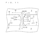
- FIGS. 11 to 15 show structures in which the sides 111 and 112 of the connecting portion 11 shown in FIG. 2 have flat areas (hereinafter referred to as "plane portions") 121b, 131b, 141b, 151b, 161b, 122b, 132b, 142b, 152b, 162b that are along the direction 95 perpendicular to the one direction 94.
- the sides 111 and 112 further have curved portions 121a, 131a, 141a, 151a, 161a, 122a, 132a, 142a, 152a, 162a.
- the plane portions 121b, 131b, 141b, 151b, 161b, 122b, 132b, 142b, 152b, 162b can be regarded as being along a direction that is perpendicular to that direction.
- the plane portions 121b and 122b are formed respectively at the ends of the sides 111 and 112 on the core portion 2 side.
- the plane portion 121b protrudes from the curved portion 121a along the one direction 94.
- the plane portion 122b protrudes from the curved portion 122a along the one direction 94.
- the plane portions 121b and 122b may be formed respectively at the ends of the sides 111 and 112 on the core portion 3 side.
- the plane portion 131b is formed at the end of the side 111 on the core portion 2 side, and the plane portion 132b is formed at the end of the side 112 on the core portion 3 side.
- the plane portion 131b protrudes from the curved portion 131a along the one direction 94.
- the plane portion 132b protrudes from the curved portion 132a along the one direction 94.
- the plane portions 141b are formed at both ends of the side 111, and the plane portions 142b are formed at both ends of the side 112.
- the plane portions 141b protrude from the curved portion 141 a along the one direction 94.
- the plane portions 142b protrude from the curved portion 142a along the one direction 94.
- the plane portions 151b are formed at both ends of the side 111, and the plane portions 152b are formed at both ends of the side 112.
- the curved portion 151a connects directly to the plane portions 151b.
- the curved portion 152a connects directly to the plane portions 152b.
- the plane portions 161b and 162b are formed respectively at the ends of the sides 111 and 112 on the core portion 3 side.
- the curved portions 161a and 162a directly connect respectively to the plane portions 161b and 162b.
- the plane portions 161b and 162b may be formed respectively at the ends of the sides 111 and 112 on the core portion 2 side.
- the configurations of the side 111 can be regarded as follows. That is, seen from the given direction 91, at least one r21, r23, r41, r42, r51, r52, r62 of the ends of the curved portion 121a, 131a, 141a, 151a, 161a connects via the plane portion 121b, 131b, 141b, 151b, 161b to the surface 21, 31 of the field magnet through hole 41 that is located on the same side as that end with respect to that curved portion 121a, 131a, 141a, 151a, 161a.
- forming the curved portions 121a, 131a, 141a, 151a, 161a, 122a, 132a, 142a, 152a, 162a on the sides 111 and 112 allows the formation of the plane portions 121b, 131b, 141b, 151b, 161b, 122b, 132b, 142b, 152b, 162b without narrowing the areas of the field magnet through holes seen from the given direction 91. Also, when magnets are inserted in the field magnet through holes 41 and 42, the magnets can be fixed at the plane portions.
- the first preferred embodiment obtained the results by simulations that setting the ratio Rb/Lm in the range of 1.0 to 1.5 reduces the maximum value of stress.
- the width Lm can be regarded as a length Ln of the curved portion of the side 111 in the perpendicular direction 95. Accordingly, it is expected that the same results will be obtained also when the width Lm adopts the length Ln of the curved portions 121a, 131a, 141a, 151a, 161a, 122a, 132a, 142a, 152a, 162a in the perpendicular direction.
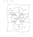
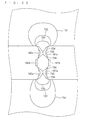
- FIG. 16 shows the results obtained by a simulation about stresses occurring in the connecting portion 11 shown in FIG. 13 , with contour lines 701 to 703.
- the contour lines 701 to 703 indicate larger stresses in this order.
- the outer diameter of the field element core 1 is 90 (mm)
- the number of rotations is 120 (/min)
- the distance Lb between the position r13 and position r16 is 0.6 (mm)
- the width Lm is 2.8 (mm)
- the length Ln is 1.8 (mm)
- the radius Rb is 2.3 (mm)
- the ratio Ln/Rb is 0.78.
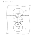
- FIGS. 17 and 18 show the results obtained by simulations about connecting portions configured differently from that shown in FIG. 13 .
- FIG. 17 shows the results about a connecting portion where the curved portions of the connecting portion 111 are made flat (these portions are referred to as "flat portions 201" here), with stress contour lines 711 to 714.
- the contour lines 711 to 714 indicate larger stresses in this order.
- the thickness of the flat portions 201 in the one direction 94 is 0.6 (mm), and the other conditions are the same as those of FIG. 16 .
- FIG. 18 shows the results about a connecting portion in which both ends of the flat portions 201 of the connecting portion shown in FIG. 17 are rounded with a radius of 0.5 (mm), with contour lines 721 to 724.
- the contour lines 721 to 724 indicate larger stresses in this order.
- the other conditions are the same as those of FIG. 16 .
- the formation of the curved portion 141 a on the side 111 alleviates the stress concentration in the connecting portion 111 even when the plane portions 141 b and 142b are formed at both ends thereof. Furthermore, the distance between the position r13 and the position r16 is reduced, and the short of magnetic flux is prevented.
- FIGS. 19(a) and (b) respectively show, in an enlarged manner, the areas surrounded by the broken lines in FIGS. 16 and 18 .
- the stress is small at the corner of the plane portion 141b on the curved portion 141a side.
- the area of the region of small stress (the region surrounded by the contour line 701 and the side 111) is larger than the area of the region surrounded by the contour line 721 and the side shown in FIG. 19(b) . That is, it is seen that stresses are not likely to concentrate in the corners when the flat portions 201 shown in FIG. 18 are curved like the curved portions 141a and 142a ( FIG. 16 ).
- FIG. 20 shows the connecting portion 11, shown in FIG.2 , when the extension direction 93 threreof is inclined, seen from the given direction 91, with respect to the direction 95 that is perpendicular to the one direction 94, as a connecting portion 17.
- the sides of the connecting portion 17 are referred to by reference numerals 171 and 172.
- the connecting portion 17 is inclined with respect to the direction that equally divides, into two, the angle that the extension direction 941 and the extension direction 942 form on the inner periphery side of the field element core 1.
- the connecting portion 17 when the connecting portion 17 is provided in a position where the radius direction around the axis of rotation of the field element core 1 is inclined with respect to the direction 95 that is perpendicular to the one direction 94, the extension direction 93 of the connecting portion 17 is along that radius direction.
- a tangent t (r33) to the side 171 is along the direction 93 of extension of the connecting portion 17 only at a certain one position r33 between both ends r31 and r32 of the side 171.
- a tangent t (r36) to the side 172 is along the extension direction 93 only at a certain one position r36 between both ends r34 and r35 of the side 172.
- This configuration prevents deformation of the connecting portion 17. This is because, when the field element core 1 is rotated around the axis of rotation that is along the given direction 91, stresses occur in the field element core 1 in the radius direction around the axis of rotation, but the direction 93 in which the connecting portion 17 extends is along the direction in which the stresses occur, and so the stress components are small in the direction perpendicular to the extension direction 93.
- the straight line A2 including the position r33 and the position r36 intersect at right angles with the direction 93 of extension of the connecting portion 17. Also, it is more desired that, seen from the given direction 91, the sides 171 and 172 be respectively along circles, the center of which is positions c171 and c172 located on the straight line A2 on the sides opposite to the connecting portion 17 with respected to the sides 171 and 172.
- Plane portions as described in the second preferred embodiment may be provided in the connecting portion 17 according to this preferred embodiment.
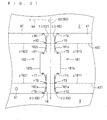
- FIG. 21 conceptually illustrates a connecting portion 18 according to this preferred embodiment.
- the sides of the connecting portion 18 are referred to by symbol 181 and 182.
- the direction 93 in which the connecting portion 18 extends is perpendicular to the one direction 94.
- the side 181 has curved portions 181a and 181c and a plane portion 181b. Seen from the given direction 91, the curved portion 181a is curved in a concave shape, and a tangent t (r73) is along the extension direction 93 only at a certain one position r73 between both ends r71 and r72 of the curved portion 181a.
- the curved portion 181c is also curved in a concave shape, and a tangent t (r76) is along the extension direction 93 only at a certain one position r76 between both its ends r74 and r75.
- the plane portion 181b is flat along the direction 95 perpendicular to the one direction 94, and is located between the curved portion 181a and the curved portion 181c. As described in the first preferred embodiment, when the one direction 94 is regarded as a direction in which the field magnet through holes 41 and 42 extend from the connecting portion 18, then the plane portion 181b can be regarded as being along the direction perpendicular to that direction.
- the plane portion 181b may protrude with respect to the curved portions 181a and 181c along the one direction 94, or the ends r71 and r75 of the curved portions 181a and 181c may connect directly to the plane portion 181b.
- FIG. 21 shows the former configuration.
- the side 182 has curved portions 182a and 182c and a plane portion 182b. Seen from the given direction, the curved portion 182a is curved in a concave shape, and a tangent t (r79) is along the extension direction 93 only at a certain one position r79 between both ends r77 and r78 of the curved portion 182a.
- the curved portion 182c is also curved in a concave shape, and a tangent t (r82) is along the extension direction 93 only at a certain one position r82 between both ends r80 and r81 thereof.
- the plane portion 182b is flat along the direction 95 perpendicular to the one direction 94, and is located between the curved portion 182a and the curved portion 182c.
- the plane portion 182b can be regarded in the same way as the plane portion 181 b.
- the plane portion 182b may protrude with respect to the curved portions 182a and 182c along the one direction 94, or the ends r77 and r81 of the curved portions 182a and 182c may directly connect to the plane portion 182b.
- FIG. 21 shows the former configuration.
- the side 181 it is possible to distribute stresses occurring in the connecting portion 18 at the curved portions 181a and 181c. Furthermore, when a magnet is inserted in the field magnet through hole 41, the magnet can be fixed on the plane portion 181b. Then, even when the end faces of the magnets toward the connecting portion 18 are curved in convex shape, the plane portions 181b and 182b can be formed in correspondence with the end faces. Similarly, the side 182 can distribute stresses and fix the magnet inserted in the field magnet through hole 42.
- the straight line A31 including the position r73 and the position r79 perpendicularly intersect with the extension direction 93.
- the straight line A32 including the position r76 and the position r82 also perpendicularly intersect with the extension direction 93.
- the length for which the plane portions 181b and 182b protrude respectively from the curved portions 181a and 182a be not more than 1/3 with respect to the width Lm.
- the curved portions 181a and 182a be respectively along circles around positions c1811 and c1821 located on the straight line A31 on the sides opposite from the connecting portion 18 with respect to the curved portions 181a and 182a. Also, it is more desired that, seen from the given direction 91, the curved portions 181c and 182c be also along circles around positions c1812 and c1822 located on the straight line A32 on the sides opposite from the connecting portion 18 seen from the curved portions 181c and 182c.
- radius Rb When the radiuses of the circles around the positions c1811 and c1821, and the radiuses of the circles around the positions c1812 and c1822, are equal to each other (hereinafter referred to as "radius Rb"), the same estimate can be made as in the third preferred embodiment, from the results of simulations described in the first preferred embodiment.
- the maximum value of stress is reduced when the ratio Rb/Ln1 of the radius Rb with respect to the length Ln1 of the curved portions 181a and 182a in the direction 95 perpendicular to the one direction 94, is set in the range of 1.0 to 1.5, and the ratio Rb/Ln2 of the radius Rb with respect to the length Ln2 of the curved portions 181c and 182c in the direction 95 is set in the range of 1.0 to 1.5.
- FIG. 22 shows the results obtained by a simulation about stresses occurring in the connecting portion 18 shown in FIG. 21 , with contour lines 731 to 735.
- the contour lines 731 to 735 indicate larger stresses in this order.
- the conditions for the simulation are: the outer diameter of the field element core 1 is 88.6 (mm), the number of rotations is 120 (/min), the distance Lb1 between the position r73 and the position r79 is 0.6 (mm), the distance Lb2 between the position r76 and the position r82 is 0.6 (mm), the width Lm is 2.8 (mm), the lengths Ln1 and Ln2 are 1.15 (mm), the radius Rb is 1.4 (mm), and the ratios Rb/Ln1, Rb/Ln2 are 1.22. Both ends of the curved portions 181a, 181c, 182a and 182c were rounded with a radius of 0.2 (mm).
- FIG. 23 shows, with contour lines 741 to 746, the results obtained by a simulation about a connecting portion configured differently from that shown in FIG. 21 .
- the contour lines 741 to 746 indicate larger stresses in this order.
- the connecting portions 181 a, 181c, 182a and 182c are all made flat (these portions are referred to as "flat portions 202"), and both ends of the flat portions 202 are rounded with a radius of 0.3 (mm).
- All of the preferred embodiments described so far are applicable also to three or more field magnet through holes that are disposed adjacent in the circumferential direction 92 to form a set. That is, one of the connecting portions 11, 17 and 18 is adopted between adjacent field magnet through holes belonging to the same set.
- the field element core 1 can be obtained by laminating magnetic steel sheets in the given direction 91 and caulking the magnetic steel sheets together.
- FIGS. 24 and 25 conceptually illustrate the positions of caulking 9.
- caulking 9 is provided on both sides of the extension direction 93 of the connecting portion 11, 17, 18. Magnetic flux is not likely to short in the connecting portions 11, 17, 18, and so the connecting portions 11, 17, 18 are likely to undergo magnetic saturation. Accordingly, magnetic flux is less likely to vary on both sides of the connecting portion 11, 17, 18, and they are desirable for the positions of the caulking 9.
- caulking 9 is provided in the core portions 2 and 3 in the vicinities of the centers of the field magnet through holes 41 and 42 in the one direction 94. This enhances the strength of the areas that are less strong than the vicinities of the connecting portion 11, 17, 18, i.e. this enhances the strength of the areas closer to the gaps 43 from the connecting portion 11, 17, 18.
- the field element core 1 may be obtained by laminating magnetic steel sheets in the given direction 91, sandwiching them with end plates from both sides in the given direction 91, and fixing the entirety with pins or bolts.
- FIG. 1 conceptually illustrates the positions of holes 6 for pins or bolts.
- holes 6 are provided between adjacent field magnet through holes 41 and 42 belonging to different pairs, in the area closer to the inner periphery of the field element core 1 from the field magnet through holes 41 and 42. Then, when a balance weight is attached to the pins or bolts, the field element core 1 is not likely to be deformed even when the centrifugal force acting on the balance weight is transmitted to the pins or bolts.
Landscapes
- Engineering & Computer Science (AREA)
- Power Engineering (AREA)
- Iron Core Of Rotating Electric Machines (AREA)
- Permanent Field Magnets Of Synchronous Machinery (AREA)
- Mram Or Spin Memory Techniques (AREA)
Applications Claiming Priority (2)
| Application Number | Priority Date | Filing Date | Title |
|---|---|---|---|
| JP2006144410A JP4274199B2 (ja) | 2006-05-24 | 2006-05-24 | 界磁子用コア |
| PCT/JP2007/060387 WO2007136041A1 (fr) | 2006-05-24 | 2007-05-21 | Noyau pour élément inducteur |
Publications (3)
| Publication Number | Publication Date |
|---|---|
| EP2020732A1 true EP2020732A1 (fr) | 2009-02-04 |
| EP2020732A4 EP2020732A4 (fr) | 2016-11-02 |
| EP2020732B1 EP2020732B1 (fr) | 2018-11-28 |
Family
ID=38723354
Family Applications (1)
| Application Number | Title | Priority Date | Filing Date |
|---|---|---|---|
| EP07743821.6A Active EP2020732B1 (fr) | 2006-05-24 | 2007-05-21 | Noyau pour élément inducteur |
Country Status (7)
| Country | Link |
|---|---|
| US (1) | US7863793B2 (fr) |
| EP (1) | EP2020732B1 (fr) |
| JP (1) | JP4274199B2 (fr) |
| KR (1) | KR100990313B1 (fr) |
| CN (1) | CN101427444B (fr) |
| AU (1) | AU2007252541B2 (fr) |
| WO (1) | WO2007136041A1 (fr) |
Cited By (3)
| Publication number | Priority date | Publication date | Assignee | Title |
|---|---|---|---|---|
| EP2509199A1 (fr) * | 2011-04-08 | 2012-10-10 | Grundfos Management A/S | Rotor |
| EP2216884A4 (fr) * | 2007-11-28 | 2014-05-14 | Daikin Ind Ltd | Noyau d'element d'excitation |
| US9246363B2 (en) | 2010-05-20 | 2016-01-26 | Nidec Sr Drives, Ltd | Reducing stress in electric-machine rotors by optimizing holes |
Families Citing this family (7)
| Publication number | Priority date | Publication date | Assignee | Title |
|---|---|---|---|---|
| JP2010088219A (ja) * | 2008-09-30 | 2010-04-15 | Mitsubishi Electric Corp | 永久磁石埋め込み型回転子及び掃除機 |
| US8618708B2 (en) * | 2011-07-29 | 2013-12-31 | General Electric Company | Electrical machine |
| JP5215486B1 (ja) * | 2011-11-14 | 2013-06-19 | ファナック株式会社 | 永久磁石同期電動機の回転子、電動機および工作機械 |
| JP5872605B2 (ja) * | 2014-03-04 | 2016-03-01 | ダイキン工業株式会社 | ロータ |
| CN106936284B (zh) | 2015-12-29 | 2024-04-16 | 丹佛斯(天津)有限公司 | 电动机 |
| ES2732777T3 (es) * | 2017-02-02 | 2019-11-25 | Keeeper Gmbh | Recipiente para alimentos portátil |
| CN112152358B (zh) * | 2020-09-29 | 2025-08-29 | 安徽美芝精密制造有限公司 | 转子冲片、转子铁芯、电机和压缩机 |
Family Cites Families (25)
| Publication number | Priority date | Publication date | Assignee | Title |
|---|---|---|---|---|
| US5097166A (en) * | 1990-09-24 | 1992-03-17 | Reuland Electric | Rotor lamination for an AC permanent magnet synchronous motor |
| JPH0830395B2 (ja) | 1993-06-25 | 1996-03-27 | 晴美 小野 | ハンマーグラブ |
| JPH0711859U (ja) | 1993-07-19 | 1995-02-21 | 株式会社安川電機 | 永久磁石形同期電動機のロータ |
| JP3485880B2 (ja) * | 1993-12-28 | 2004-01-13 | 三洋電機株式会社 | 圧縮機用電動機の回転子 |
| JPH09294344A (ja) * | 1996-04-26 | 1997-11-11 | Meidensha Corp | 永久磁石式回転機の回転子 |
| WO1998040952A1 (fr) * | 1997-03-13 | 1998-09-17 | Matsushita Electric Industrial Co., Ltd. | Noyau de rotor pour moteur a reluctance |
| US6008559A (en) * | 1997-07-22 | 1999-12-28 | Matsushita Electric Industrial Co., Ltd. | Motor using a rotor including an interior permanent magnet |
| JPH11206051A (ja) * | 1998-01-09 | 1999-07-30 | Yaskawa Electric Corp | 内磁形モータのロータ構造 |
| JP4363746B2 (ja) * | 2000-05-25 | 2009-11-11 | 株式会社東芝 | 永久磁石式リラクタンス型回転電機 |
| JP4244111B2 (ja) | 2000-08-18 | 2009-03-25 | 株式会社安川電機 | 永久磁石形同期電動機のロータ |
| JP2002281700A (ja) * | 2001-03-23 | 2002-09-27 | Fuji Electric Co Ltd | 埋込み磁石型回転機の回転子 |
| JP2002320363A (ja) * | 2001-04-20 | 2002-10-31 | Denso Corp | 車両用発電電動機 |
| JP2002359942A (ja) * | 2001-05-31 | 2002-12-13 | Meidensha Corp | 永久磁石型回転電機のロータ構造 |
| JP2003153508A (ja) * | 2001-08-29 | 2003-05-23 | Matsushita Electric Ind Co Ltd | 電動機 |
| JP3838073B2 (ja) * | 2001-11-01 | 2006-10-25 | Jfeスチール株式会社 | ラミネート金属帯の加熱方法およびその装置 |
| JP2003174747A (ja) * | 2001-12-05 | 2003-06-20 | Meidensha Corp | 回転機のロータ |
| JP3818205B2 (ja) * | 2002-04-15 | 2006-09-06 | 株式会社デンソー | インナーロータ型回転電機の永久磁石ロータ |
| FI116756B (fi) * | 2002-08-26 | 2006-02-15 | Abb Oy | Kestomagnetoidun sähkökoneen roottori ja menetelmä sen valmistamiseksi |
| US6946766B2 (en) * | 2002-08-28 | 2005-09-20 | Emerson Electric Co. | Permanent magnet machine |
| JP4314816B2 (ja) * | 2002-11-28 | 2009-08-19 | ダイキン工業株式会社 | ブラシレスdcモータおよびブラシレスdcモータ制御装置 |
| JP2004260888A (ja) | 2003-02-25 | 2004-09-16 | Meidensha Corp | 回転電機の回転子 |
| JP2005102460A (ja) * | 2003-08-29 | 2005-04-14 | Toyota Motor Corp | 回転電機の回転子 |
| US7786641B2 (en) * | 2005-02-28 | 2010-08-31 | Daikin Industries, Ltd. | Magnetic member, rotor and motor |
| JP4898201B2 (ja) * | 2005-12-01 | 2012-03-14 | アイチエレック株式会社 | 永久磁石回転機 |
| US7385328B2 (en) * | 2006-05-23 | 2008-06-10 | Reliance Electric Technologies, Llc | Cogging reduction in permanent magnet machines |
-
2006
- 2006-05-24 JP JP2006144410A patent/JP4274199B2/ja not_active Expired - Fee Related
-
2007
- 2007-05-21 AU AU2007252541A patent/AU2007252541B2/en not_active Ceased
- 2007-05-21 US US12/226,914 patent/US7863793B2/en active Active
- 2007-05-21 WO PCT/JP2007/060387 patent/WO2007136041A1/fr not_active Ceased
- 2007-05-21 KR KR1020087024083A patent/KR100990313B1/ko active Active
- 2007-05-21 EP EP07743821.6A patent/EP2020732B1/fr active Active
- 2007-05-21 CN CN2007800143094A patent/CN101427444B/zh active Active
Non-Patent Citations (1)
| Title |
|---|
| See references of WO2007136041A1 * |
Cited By (4)
| Publication number | Priority date | Publication date | Assignee | Title |
|---|---|---|---|---|
| EP2216884A4 (fr) * | 2007-11-28 | 2014-05-14 | Daikin Ind Ltd | Noyau d'element d'excitation |
| US9246363B2 (en) | 2010-05-20 | 2016-01-26 | Nidec Sr Drives, Ltd | Reducing stress in electric-machine rotors by optimizing holes |
| EP2509199A1 (fr) * | 2011-04-08 | 2012-10-10 | Grundfos Management A/S | Rotor |
| WO2012136576A1 (fr) * | 2011-04-08 | 2012-10-11 | Grundfos Management A/S | Rotor |
Also Published As
| Publication number | Publication date |
|---|---|
| EP2020732A4 (fr) | 2016-11-02 |
| EP2020732B1 (fr) | 2018-11-28 |
| KR20080098685A (ko) | 2008-11-11 |
| JP2007318880A (ja) | 2007-12-06 |
| KR100990313B1 (ko) | 2010-10-26 |
| AU2007252541A1 (en) | 2007-11-29 |
| WO2007136041A1 (fr) | 2007-11-29 |
| CN101427444B (zh) | 2011-07-27 |
| US20090102306A1 (en) | 2009-04-23 |
| US7863793B2 (en) | 2011-01-04 |
| JP4274199B2 (ja) | 2009-06-03 |
| AU2007252541B2 (en) | 2011-01-20 |
| CN101427444A (zh) | 2009-05-06 |
Similar Documents
| Publication | Publication Date | Title |
|---|---|---|
| EP2020732B1 (fr) | Noyau pour élément inducteur | |
| EP2216884B1 (fr) | Noyau d'element d'excitation | |
| EP2463988A2 (fr) | Moteur électrique | |
| US20170338707A1 (en) | Rotor for rotary electrical machine | |
| EP2600499B1 (fr) | Rotor pour machine électrique rotative | |
| DE112014000526B4 (de) | Rotor und drehende elektrische Maschine, die diesen Rotor enthält | |
| US10594177B2 (en) | Rotary electric machine and rotor core manufacturing method | |
| EP2894768B1 (fr) | Rotor de moteur à aimant permanent | |
| US10396609B2 (en) | Permanent magnet-embedded type rotary electric machine with rotor having slots and rotor surface grooves | |
| CN103026586A (zh) | 电动机用转子 | |
| CN102017367A (zh) | 励磁元件 | |
| CN102986116A (zh) | 永久磁铁埋入型转子以及旋转电机 | |
| JP2002165394A (ja) | 永久磁石内蔵型同期モータ | |
| CN113489183A (zh) | 一种自斜极的永磁电机转子冲片及永磁电机 | |
| JP5261965B2 (ja) | 回転子 | |
| US20220416600A1 (en) | Rotor core and rotating electrical machine | |
| US11349361B2 (en) | Rotor core | |
| CN109253212B (zh) | 具有减小的质量和惯性的平衡轴 | |
| EP4637004A1 (fr) | Rotor, noyau de rotor, moteur à induction et procédé de conception pour moteur à induction | |
| EP4668547A1 (fr) | Noyau rotorique, rotor, machine électrique tournante, et procédé de conception de noyau rotorique | |
| EP4250536A1 (fr) | Rotors, machines à réluctance, systèmes et procédés de fabrication de rotors | |
| JP2019054696A (ja) | モータ |
Legal Events
| Date | Code | Title | Description |
|---|---|---|---|
| PUAI | Public reference made under article 153(3) epc to a published international application that has entered the european phase |
Free format text: ORIGINAL CODE: 0009012 |
|
| 17P | Request for examination filed |
Effective date: 20081106 |
|
| AK | Designated contracting states |
Kind code of ref document: A1 Designated state(s): AT BE BG CH CY CZ DE DK EE ES FI FR GB GR HU IE IS IT LI LT LU LV MC MT NL PL PT RO SE SI SK TR |
|
| AX | Request for extension of the european patent |
Extension state: AL BA HR MK RS |
|
| DAX | Request for extension of the european patent (deleted) | ||
| RA4 | Supplementary search report drawn up and despatched (corrected) |
Effective date: 20161005 |
|
| RIC1 | Information provided on ipc code assigned before grant |
Ipc: H02K 1/27 20060101AFI20160928BHEP Ipc: H02K 1/22 20060101ALI20160928BHEP |
|
| GRAP | Despatch of communication of intention to grant a patent |
Free format text: ORIGINAL CODE: EPIDOSNIGR1 |
|
| STAA | Information on the status of an ep patent application or granted ep patent |
Free format text: STATUS: GRANT OF PATENT IS INTENDED |
|
| INTG | Intention to grant announced |
Effective date: 20180719 |
|
| GRAS | Grant fee paid |
Free format text: ORIGINAL CODE: EPIDOSNIGR3 |
|
| GRAA | (expected) grant |
Free format text: ORIGINAL CODE: 0009210 |
|
| STAA | Information on the status of an ep patent application or granted ep patent |
Free format text: STATUS: THE PATENT HAS BEEN GRANTED |
|
| AK | Designated contracting states |
Kind code of ref document: B1 Designated state(s): AT BE BG CH CY CZ DE DK EE ES FI FR GB GR HU IE IS IT LI LT LU LV MC MT NL PL PT RO SE SI SK TR |
|
| REG | Reference to a national code |
Ref country code: GB Ref legal event code: FG4D |
|
| REG | Reference to a national code |
Ref country code: CH Ref legal event code: EP |
|
| REG | Reference to a national code |
Ref country code: DE Ref legal event code: R096 Ref document number: 602007056972 Country of ref document: DE |
|
| REG | Reference to a national code |
Ref country code: AT Ref legal event code: REF Ref document number: 1071385 Country of ref document: AT Kind code of ref document: T Effective date: 20181215 |
|
| REG | Reference to a national code |
Ref country code: IE Ref legal event code: FG4D |
|
| REG | Reference to a national code |
Ref country code: NL Ref legal event code: MP Effective date: 20181128 |
|
| REG | Reference to a national code |
Ref country code: LT Ref legal event code: MG4D |
|
| REG | Reference to a national code |
Ref country code: AT Ref legal event code: MK05 Ref document number: 1071385 Country of ref document: AT Kind code of ref document: T Effective date: 20181128 |
|
| PG25 | Lapsed in a contracting state [announced via postgrant information from national office to epo] |
Ref country code: AT Free format text: LAPSE BECAUSE OF FAILURE TO SUBMIT A TRANSLATION OF THE DESCRIPTION OR TO PAY THE FEE WITHIN THE PRESCRIBED TIME-LIMIT Effective date: 20181128 Ref country code: LV Free format text: LAPSE BECAUSE OF FAILURE TO SUBMIT A TRANSLATION OF THE DESCRIPTION OR TO PAY THE FEE WITHIN THE PRESCRIBED TIME-LIMIT Effective date: 20181128 Ref country code: BG Free format text: LAPSE BECAUSE OF FAILURE TO SUBMIT A TRANSLATION OF THE DESCRIPTION OR TO PAY THE FEE WITHIN THE PRESCRIBED TIME-LIMIT Effective date: 20190228 Ref country code: ES Free format text: LAPSE BECAUSE OF FAILURE TO SUBMIT A TRANSLATION OF THE DESCRIPTION OR TO PAY THE FEE WITHIN THE PRESCRIBED TIME-LIMIT Effective date: 20181128 Ref country code: LT Free format text: LAPSE BECAUSE OF FAILURE TO SUBMIT A TRANSLATION OF THE DESCRIPTION OR TO PAY THE FEE WITHIN THE PRESCRIBED TIME-LIMIT Effective date: 20181128 Ref country code: IS Free format text: LAPSE BECAUSE OF FAILURE TO SUBMIT A TRANSLATION OF THE DESCRIPTION OR TO PAY THE FEE WITHIN THE PRESCRIBED TIME-LIMIT Effective date: 20190328 Ref country code: FI Free format text: LAPSE BECAUSE OF FAILURE TO SUBMIT A TRANSLATION OF THE DESCRIPTION OR TO PAY THE FEE WITHIN THE PRESCRIBED TIME-LIMIT Effective date: 20181128 |
|
| PG25 | Lapsed in a contracting state [announced via postgrant information from national office to epo] |
Ref country code: SE Free format text: LAPSE BECAUSE OF FAILURE TO SUBMIT A TRANSLATION OF THE DESCRIPTION OR TO PAY THE FEE WITHIN THE PRESCRIBED TIME-LIMIT Effective date: 20181128 Ref country code: GR Free format text: LAPSE BECAUSE OF FAILURE TO SUBMIT A TRANSLATION OF THE DESCRIPTION OR TO PAY THE FEE WITHIN THE PRESCRIBED TIME-LIMIT Effective date: 20190301 Ref country code: PT Free format text: LAPSE BECAUSE OF FAILURE TO SUBMIT A TRANSLATION OF THE DESCRIPTION OR TO PAY THE FEE WITHIN THE PRESCRIBED TIME-LIMIT Effective date: 20190328 |
|
| PG25 | Lapsed in a contracting state [announced via postgrant information from national office to epo] |
Ref country code: NL Free format text: LAPSE BECAUSE OF FAILURE TO SUBMIT A TRANSLATION OF THE DESCRIPTION OR TO PAY THE FEE WITHIN THE PRESCRIBED TIME-LIMIT Effective date: 20181128 |
|
| PG25 | Lapsed in a contracting state [announced via postgrant information from national office to epo] |
Ref country code: DK Free format text: LAPSE BECAUSE OF FAILURE TO SUBMIT A TRANSLATION OF THE DESCRIPTION OR TO PAY THE FEE WITHIN THE PRESCRIBED TIME-LIMIT Effective date: 20181128 Ref country code: CZ Free format text: LAPSE BECAUSE OF FAILURE TO SUBMIT A TRANSLATION OF THE DESCRIPTION OR TO PAY THE FEE WITHIN THE PRESCRIBED TIME-LIMIT Effective date: 20181128 Ref country code: PL Free format text: LAPSE BECAUSE OF FAILURE TO SUBMIT A TRANSLATION OF THE DESCRIPTION OR TO PAY THE FEE WITHIN THE PRESCRIBED TIME-LIMIT Effective date: 20181128 |
|
| REG | Reference to a national code |
Ref country code: DE Ref legal event code: R097 Ref document number: 602007056972 Country of ref document: DE |
|
| PG25 | Lapsed in a contracting state [announced via postgrant information from national office to epo] |
Ref country code: RO Free format text: LAPSE BECAUSE OF FAILURE TO SUBMIT A TRANSLATION OF THE DESCRIPTION OR TO PAY THE FEE WITHIN THE PRESCRIBED TIME-LIMIT Effective date: 20181128 Ref country code: SK Free format text: LAPSE BECAUSE OF FAILURE TO SUBMIT A TRANSLATION OF THE DESCRIPTION OR TO PAY THE FEE WITHIN THE PRESCRIBED TIME-LIMIT Effective date: 20181128 Ref country code: EE Free format text: LAPSE BECAUSE OF FAILURE TO SUBMIT A TRANSLATION OF THE DESCRIPTION OR TO PAY THE FEE WITHIN THE PRESCRIBED TIME-LIMIT Effective date: 20181128 |
|
| PLBE | No opposition filed within time limit |
Free format text: ORIGINAL CODE: 0009261 |
|
| STAA | Information on the status of an ep patent application or granted ep patent |
Free format text: STATUS: NO OPPOSITION FILED WITHIN TIME LIMIT |
|
| PG25 | Lapsed in a contracting state [announced via postgrant information from national office to epo] |
Ref country code: SI Free format text: LAPSE BECAUSE OF FAILURE TO SUBMIT A TRANSLATION OF THE DESCRIPTION OR TO PAY THE FEE WITHIN THE PRESCRIBED TIME-LIMIT Effective date: 20181128 |
|
| 26N | No opposition filed |
Effective date: 20190829 |
|
| REG | Reference to a national code |
Ref country code: CH Ref legal event code: PL |
|
| PG25 | Lapsed in a contracting state [announced via postgrant information from national office to epo] |
Ref country code: CH Free format text: LAPSE BECAUSE OF NON-PAYMENT OF DUE FEES Effective date: 20190531 Ref country code: MC Free format text: LAPSE BECAUSE OF FAILURE TO SUBMIT A TRANSLATION OF THE DESCRIPTION OR TO PAY THE FEE WITHIN THE PRESCRIBED TIME-LIMIT Effective date: 20181128 Ref country code: LI Free format text: LAPSE BECAUSE OF NON-PAYMENT OF DUE FEES Effective date: 20190531 |
|
| REG | Reference to a national code |
Ref country code: BE Ref legal event code: MM Effective date: 20190531 |
|
| PG25 | Lapsed in a contracting state [announced via postgrant information from national office to epo] |
Ref country code: LU Free format text: LAPSE BECAUSE OF NON-PAYMENT OF DUE FEES Effective date: 20190521 |
|
| PG25 | Lapsed in a contracting state [announced via postgrant information from national office to epo] |
Ref country code: TR Free format text: LAPSE BECAUSE OF FAILURE TO SUBMIT A TRANSLATION OF THE DESCRIPTION OR TO PAY THE FEE WITHIN THE PRESCRIBED TIME-LIMIT Effective date: 20181128 |
|
| PG25 | Lapsed in a contracting state [announced via postgrant information from national office to epo] |
Ref country code: IE Free format text: LAPSE BECAUSE OF NON-PAYMENT OF DUE FEES Effective date: 20190521 |
|
| PG25 | Lapsed in a contracting state [announced via postgrant information from national office to epo] |
Ref country code: BE Free format text: LAPSE BECAUSE OF NON-PAYMENT OF DUE FEES Effective date: 20190531 |
|
| PG25 | Lapsed in a contracting state [announced via postgrant information from national office to epo] |
Ref country code: CY Free format text: LAPSE BECAUSE OF FAILURE TO SUBMIT A TRANSLATION OF THE DESCRIPTION OR TO PAY THE FEE WITHIN THE PRESCRIBED TIME-LIMIT Effective date: 20181128 |
|
| PG25 | Lapsed in a contracting state [announced via postgrant information from national office to epo] |
Ref country code: HU Free format text: LAPSE BECAUSE OF FAILURE TO SUBMIT A TRANSLATION OF THE DESCRIPTION OR TO PAY THE FEE WITHIN THE PRESCRIBED TIME-LIMIT; INVALID AB INITIO Effective date: 20070521 Ref country code: MT Free format text: LAPSE BECAUSE OF FAILURE TO SUBMIT A TRANSLATION OF THE DESCRIPTION OR TO PAY THE FEE WITHIN THE PRESCRIBED TIME-LIMIT Effective date: 20181128 |
|
| REG | Reference to a national code |
Ref country code: FR Ref legal event code: PLFP Year of fee payment: 17 |
|
| P01 | Opt-out of the competence of the unified patent court (upc) registered |
Effective date: 20230525 |
|
| PGFP | Annual fee paid to national office [announced via postgrant information from national office to epo] |
Ref country code: DE Payment date: 20250402 Year of fee payment: 19 |
|
| PGFP | Annual fee paid to national office [announced via postgrant information from national office to epo] |
Ref country code: IT Payment date: 20250422 Year of fee payment: 19 |
|
| PGFP | Annual fee paid to national office [announced via postgrant information from national office to epo] |
Ref country code: FR Payment date: 20250401 Year of fee payment: 19 |
|
| PGFP | Annual fee paid to national office [announced via postgrant information from national office to epo] |
Ref country code: GB Payment date: 20260323 Year of fee payment: 20 |