EP2021115B1 - Appareil d'agglomération et procédé de fabrication de particules agglomérées - Google Patents
Appareil d'agglomération et procédé de fabrication de particules agglomérées Download PDFInfo
- Publication number
- EP2021115B1 EP2021115B1 EP06722930A EP06722930A EP2021115B1 EP 2021115 B1 EP2021115 B1 EP 2021115B1 EP 06722930 A EP06722930 A EP 06722930A EP 06722930 A EP06722930 A EP 06722930A EP 2021115 B1 EP2021115 B1 EP 2021115B1
- Authority
- EP
- European Patent Office
- Prior art keywords
- particles
- agglomeration
- fluid bed
- nozzle
- fluidised
- Prior art date
- Legal status (The legal status is an assumption and is not a legal conclusion. Google has not performed a legal analysis and makes no representation as to the accuracy of the status listed.)
- Expired - Lifetime
Links
Images


Classifications
-
- B—PERFORMING OPERATIONS; TRANSPORTING
- B01—PHYSICAL OR CHEMICAL PROCESSES OR APPARATUS IN GENERAL
- B01J—CHEMICAL OR PHYSICAL PROCESSES, e.g. CATALYSIS OR COLLOID CHEMISTRY; THEIR RELEVANT APPARATUS
- B01J2/00—Processes or devices for granulating materials, e.g. fertilisers in general; Rendering particulate materials free flowing in general, e.g. making them hydrophobic
- B01J2/16—Processes or devices for granulating materials, e.g. fertilisers in general; Rendering particulate materials free flowing in general, e.g. making them hydrophobic by suspending the powder material in a gas, e.g. in fluidised beds or as a falling curtain
-
- B—PERFORMING OPERATIONS; TRANSPORTING
- B29—WORKING OF PLASTICS; WORKING OF SUBSTANCES IN A PLASTIC STATE IN GENERAL
- B29B—PREPARATION OR PRETREATMENT OF THE MATERIAL TO BE SHAPED; MAKING GRANULES OR PREFORMS; RECOVERY OF PLASTICS OR OTHER CONSTITUENTS OF WASTE MATERIAL CONTAINING PLASTICS
- B29B9/00—Making granules
- B29B9/08—Making granules by agglomerating smaller particles
-
- F—MECHANICAL ENGINEERING; LIGHTING; HEATING; WEAPONS; BLASTING
- F26—DRYING
- F26B—DRYING SOLID MATERIALS OR OBJECTS BY REMOVING LIQUID THEREFROM
- F26B3/00—Drying solid materials or objects by processes involving the application of heat
- F26B3/02—Drying solid materials or objects by processes involving the application of heat by convection, i.e. heat being conveyed from a heat source to the materials or objects to be dried by a gas or vapour, e.g. air
- F26B3/06—Drying solid materials or objects by processes involving the application of heat by convection, i.e. heat being conveyed from a heat source to the materials or objects to be dried by a gas or vapour, e.g. air the gas or vapour flowing through the materials or objects to be dried
- F26B3/08—Drying solid materials or objects by processes involving the application of heat by convection, i.e. heat being conveyed from a heat source to the materials or objects to be dried by a gas or vapour, e.g. air the gas or vapour flowing through the materials or objects to be dried so as to loosen them, e.g. to form a fluidised bed
-
- B—PERFORMING OPERATIONS; TRANSPORTING
- B29—WORKING OF PLASTICS; WORKING OF SUBSTANCES IN A PLASTIC STATE IN GENERAL
- B29L—INDEXING SCHEME ASSOCIATED WITH SUBCLASS B29C, RELATING TO PARTICULAR ARTICLES
- B29L2031/00—Other particular articles
- B29L2031/772—Articles characterised by their shape and not otherwise provided for
Definitions
- the present invention relates to an agglomeration apparatus and a method for producing agglomerated particles.
- the present invention is useful for increasing the particle size and for removing or reducing the amount of dust in the final product.
- a narrow particle size distribution of the agglomerated particles may be obtained.
- DE 43 04 405 discloses an agglomeration apparatus comprising a fluid bed, a source of ascending particles, a nozzle for atomising an agglomeration fluid, said nozzle being positioned below the surface of the fluidised particle layer and pointing in the upward direction and an outlet for discharging the agglomerated particles, further provided with an outer zone and an inner zone.
- EP 1 227 732 B1 suggests agglomerating particles in a spray dryer having an integrated fluid bed in the bottom and a flexible filter element in the top of the drying chamber. Optimal agglomeration is obtained along the inner surface of a part of the conical bottom section of the spray drying chamber, thereby substantially reducing the amount of fine particles.
- US 5,695,701 discloses an apparatus for the preparation of an agglomerated material from a liquid.
- the apparatus has a trough-shaped fluidizing path in the bottom and a nozzle for spraying an atomized liquid on the fluidized powder.
- Perforations in a perforated plate are arranged such that the fluidizing gas is directed i.a. in a direction perpendicular to the longitudinal direction of the trough-shaped path.
- a row of filters may be arranged through which filters the leaving gas flow passes in such a way that the fine par-ticles entrained therewith are separated and fall back into the fluidized layer.
- US 5,044,093 discloses a spray drying granulation apparatus having a fluid bed in the bottom of the spray drying chamber.
- a binder supply nozzle may be provided in the perforated plate of the fluid bed part of the apparatus.
- the nozzle ejects atomized binder liquid vertically upwards and the droplets collide with the particles in the fluid bed.
- the binder supply nozzle is spraying into a so-called Wurster tube, separating the spraying zone from the remainder of the fluid bed.
- the growing particles are circulated in the fluid bed between the zones on each side of the Wurster tube wall until a sufficient size has been obtained.
- US 5,615,493 (Niro ) describes a spray drying device comprising a fluid bed at the bottom of the drying chamber.
- the fluid bed is divided into a central back-mix section and a surrounding annular plug-flow section shielded from descending spray-dried particles.
- nozzles may be arranged for spraying a suitable liquid on the particles in view of obtaining a further agglomeration thereof.
- the plug-flow along the inner circumference of the fluid bed is attained due to the constant feeding of the annular section with particles from the central section and the corresponding withdrawal of dried agglomerated particles through e.g. an overflow slot.
- an agglomeration may be obtained of the particles.
- the treatment of the particles in the prior art apparatuses and the atomizing of agglomeration fluid are not sufficiently well-defined for a uniform agglomeration to take place.
- the object of the present invention is to provide an apparatus which may perform a more uniform and controlled agglomeration process. Especially, it is desired to avoid or reduce the amount of fine particles in the final product to eliminate dust problems during handling of the agglomerates.
- the present invention provides an agglomeration apparatus comprising
- the descending particles are primarily received by an outer zone and guided towards the outlet in an inner zone. It may be ensured by a variety of ways that a majority of the descending particles are received by the outer zone.
- the outer zone is allocated an active fluidisation area of the fluid bed greater than 50%, preferably greater than 70%.
- a conical wall is provided above the fluid bed. The conical wall concentrates the descending particles and the particles are delivered at the inner perimeter of the fluid bed. The descending particles are subsequently agglomerated in a controlled fashion in the outer zone.
- the outer zone is preferably at least in a part of the flow path delimited by the wall of the fluid bed. In the outer zone a plug-flow is suitably maintained to obtain a uniform treatment of the descending particles.
- the means establishing different fluidisation gas flow velocities in the zones are generally adjusted such that the zone closest to the outlet is provided with a higher fluidisation gas velocity compared to the preceding zone.
- the higher fluidisation gas flow velocity in the inner zone ensures that the growing particles are maintained in a fluidised state and that minor particles are blown away.
- the presence of an atomizing nozzle capable of atomizing an agglomeration fluid in the uniformly conveyed, fluidised layer provides for an equal wetting of the fluidised particles and, in consequence, an optimal agglomeration.
- the outer zone may be provided with two or more sections in which the fluidisation gas flow velocity is altered.
- the sections with different fluidisation gas velocities may be provided in the bottom of the fluid bed by a variety of methods.
- the plenum below the perforated plate is designed to direct more fluidisation gas to a certain section.
- the perforations of the perforated plate are larger in the section having the highest gas flow velocity and, conversely, smaller in a section having a lower gas flow velocity.
- the different zones are supplied with fluidisation gas from separate plenums.
- the fluid bed comprises at least one partition wall provided in the fluidised particle layer.
- the at least one partition wall generally separates the inner and the outer zones.
- the partition wall may be arranged in the entire vertical extent of the fluidised layer or only in a part thereof. In a preferred aspect, the partition wall abuts the perforated plate of the fluid bed and extends essentially vertically upwards.
- the partition wall may be provided to define a flow path of the particles.
- the shape of the partition wall depends, among other things, on the inner form of the fluid bed.
- the flow path of the fluidised particles in the outer zone follows the inner circumference of the fluid bed wall.
- the partition wall may be a cylinder part placed co-axially in the fluid bed.
- an at least partly cylindrical partition wall is provided co-axially in the fluid bed, thereby defining a plug-flow path for the fluidised particles between the interior circumference of the fluid bed and the partition wall.
- the defined flow path of the agglomerated particles ends in an outlet, which is connected to the inner zone.
- the outlet is arranged via the bottom of the fluid bed.
- the outlet is generally provided with means for controlled particle removal, such as an overflow slot.
- the outlet for the agglomerated particles is positioned substantially in the centre of the fluid bed. The position of the outlet in the fluid bed centre allows for an easy adaption of the invention to existing spray dryers.
- the flow path of the particles starting at the circumference and ending in the centre of the fluid bed uses the drying capacity in an optimal way.
- the source of descending particles is not limited to particles prepared by a particular technology.
- the descending particles may be substantially dry or partly dried.
- the descending particles contain an amount of moisture, which allows them to agglomerate to some degree before reaching the fluidised layer.
- the source of descending particles is selected from the group comprising a spray dryer, a filter unit, and a cyclone.
- shielding means to separate the cyclone and the fluid bed are provided.
- a spray dryer is preferred as the source of descending particles.
- the walls are generally conical and meet the cylindrical walls of the fluid bed.
- the fluid bed is provided in the lower part of a spray drying chamber, said fluid bed receiving the descending, partly dried, particles from the spray dryer.
- the particles are believed to slide down the conical walls of the drying chamber, thereby being concentrated in the outer zone.
- a spray dryer and a filter unit is combined, such that the spray drying chamber comprises internally arranged filters.
- the filters are flexible filter bags mounted in the ceiling of the spray drying chamber and operated intermediately by a counter blow to release particles from the filter. The particles descend from the filters and are mixed with the partly dried particles from the spray dryer in an agglomeration area of the drying chamber. The partly dried and partly agglomerated particles continue to descend into the fluid bed.
- one or more nozzles for atomizing an agglomeration fluid are provided, said nozzles being positioned below the surface of the fluidised particle layer and pointing in an upward direction.
- Nozzles pointing upward include nozzles pointing in an essentially vertical direction as well as nozzles pointing until 90 degrees off-axis relative to the vertical direction. If only a single nozzle is used, it is generally placed in the outer zone. The inner zone then serves to dry the agglomerated particles. If desired, more than a single nozzle may be provided in the outer zone.
- agglomeration nozzles are arranged along the plug-flow path of the fluidised particles.
- the nozzles may be evenly distributed throughout the flow path, i.e. provided in each zone or may be concentrated in some sections. In the event that a concentration of nozzles appears, it is generally preferred to concentrate the nozzles in the first part of the outer zone and/or mid part of the flow path.
- the nozzle may be adjustable in height. In some applications of the present apparatus, the nozzles are in the same level as the perforated plate. However, it may be appropriate to place the nozzle either below or above the level of the perforated plate. In the event that more than a single nozzle is provided, the nozzles may be provided in different heights.
- the agglomeration nozzle may further be provided with a tube arranged co-axially around the nozzle for supplying a secondary fluidization gas around the atomized fluid.
- the secondary gas may be liberated through an orifice to secure the proper velocity to enhance the interaction between the particles in the fluidised layer and the atomized agglomeration liquid. It may be an advantage in the supply line for the secondary fluidisation gas to provide swirling means to increase the efficiency.
- the agglomeration nozzle and/or the tube arranged co-axially around the agglomeration nozzle may be adjustable in height.
- the invention also provides a method for producing agglomerated particles, the method comprising the steps of:
- the controlled plug-flow is an advantage.
- the uniform treatment of the particles has surprisingly resulted in an improved bulk density of the final product. Based on experiments with prior art technology in the field, it was expected that the density of the product would decrease considerably during the agglomeration process. However, in a specific sample, the bulk density was maintained at the same value.
- the fluidisation gas flow velocity of the inner zone connected to the outlet is higher than the fluidisation gas flow velocity in the outer zone.
- the increased fluidisation gas flow velocities along the path of the fluidised particles accounts for an increased probability of the fine particles to agglomerate. The result is a final product containing only a minor or negligible fraction of small particles.
- the sections provided with different fluidisation gas flow velocities are provided with at least one atomisation nozzle in each section.
- the nozzle for ejecting the agglomeration fluid is a two-fluid nozzle
- the nozzle is provided with a supply of nozzle gas.
- a secondary fluidization gas may preferably be added around the nozzle to increase the velocity around the same with the purpose of improving the interaction between the particles and the agglomeration fluid.
- the high velocity creates a local under-pressure securing a sufficient particle movement.
- Such secondary gas typically has a velocity of 5 to 50 m/s.
- the supply line for secondary fluidization gas may include means, e.g. such as vanes, for creating a swirl on the gas flow to increase the effect.
- the difference in fluidisation gas flow velocities in the various zones or sections may be regulated to obtain the desired flow properties.
- the passage from one zone or section to another is continued without any sharp borderline.
- it is desired to control the flow by stepwise increasing the gas flow velocity along the path of the fluidised particles.
- the fluidisation gas velocity in the inner zone proximal to the outlet is at least 5% higher than the adjacent zone or section in the fluid bed.
- the gas flow velocity is generally in the range 0.3 to 3.0 m/s, preferably 0.5 to 1.5 m/s, and a preceding zone or section may have gas flow velocity which is about 5% to about 40% lower.
- the gas flow velocity in the zone closest to the outlet is about 1.0 m/s and the gas flow velocity in the preceding zone is about 0.9 m/s.
- the descending particles may be agglomerated in various degrees.
- the mean particle size of the discharged particles is at least doubled compared to the incoming descending particles.
- the particle size distribution is in general modified by the present invention because the lightest particles in a certain zone are blown higher into the drying chamber. In the area above the fluid bed, the lighter particles may agglomerate when interacting with partly dried particles from the spray dryer.
- the particle size distribution is generally narrower compared to a process in which fluid bed back-mix agglomeration technology is used.
- An advantage of the agglomeration method according to the invention is that a more safe process may be used and at the same time the other advantages mentioned may be achieved.
- prior art agglomeration in a spray dryer demanded that a product with a higher moist content descended into the fluid bed to secure the agglomeration.
- the particles with high moisture content are more prone to form lumps and the process is conducted closer to dryer limits.
- a traditional FSDTM spray dryer may e.g. have 3-5% moist in the fluidized particles, whereas, in a FSD-GRANULATORTM according to the method of the invention, the same product may have 1-4% moist.
- the bulk density of the discharged particles is substantially the same as the bulk density of the incoming descending particles, i.e. the bulk density after agglomeration shows substantially the same value (measured in g/ml) as if no nozzles were used.
- the agglomerates are nearly always of a lower bulk density than the bulk density of the descending particles. Therefore, the present method is more versatile than the previous available methods.
- the agglomeration fluid may have any suitable composition.
- the agglomeration fluid may be water or may have essentially the same dry matter composition as the incoming descending particles.
- the agglomeration fluid may be a melt.
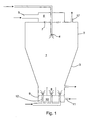
- Fig. 1 an embodiment of the invention is disclosed (the Niro FSD-GRANULATORTM ).
- the architecture of the fluid bed is shown from different perspectives in Fig. 4 and Fig. 5 .
- a drying chamber 1 having an upper cylindrical part 2 and a lower downward tapering frusto-conical part 3.
- an atomizer 4 is provided in the upper part of the drying chamber.
- the atomizer shown is a nozzle. Any suitable nozzle may be used, e.g. a two-fluid nozzle or a pressure nozzle, but alternatively rotary atomizers can be used as well.
- a fan or similar means introduce a drying gas, usually air, at 5.
- the gas is conveyed to an air disperser 6 and introduced in the drying chamber through an annular orifice 7 around the atomizer.
- the gas flow entering at 5 and the temperature of the drying gas supplied to the spraying chamber can normally be controlled for obtaining the desired drying capacity.
- the particles ejected from the atomizer are partly dried by the drying gas to moist particles.
- the particles are carried in a downward widering direction.
- agglomeration is generally observed.
- a fluid bed 8 is provided as an extension.
- the fluid bed comprises a perforated plate 9 and a plenum 10.
- the perforations in the perforated plate may have any suitable shape adapted to the specific particles being treated and may direct the fluidisation gas in various directions.
- the shape of the perforations may be designed so as to avoid that particles can pass through these perforations or to improve the sanitary conditions in the fluid bed.
- the perforations may be designed to assist in the transport of the fluidised particles towards the outlet.
- perforated plate Specific embodiments of the perforated plate are disclosed in US 5,357,688 (Niro, FLEX PLATETM), US 5,392,531 (Niro, NON-SIFTING GILL PLATETM), US 5,839,207 (Niro, BUBBLE PLATETM), and US 5,695,701 (Niro ).
- the perforations successively become larger toward the zone most proximal to the outlet to provide for an increasing fluidisation gas velocity.
- the plenum 10 distributes the fluidisation gas to each zone.
- a fan (not shown) feeds the plenum with gas (air) at a fluidisation gas inlet 11.
- means may be provided to direct the fluidisation gas to specific sections. Such means include baffles and screens to provide for different fluidisation gas flow velocities in the sections.
- each section may be provided with separate plenums. Thus, each section may be connected to a separate fan or similar means that allow for a regulation of the gas flow to each section.
- Nozzles 12 for atomizing an agglomeration fluid are provided in the fluid bed.
- the nozzles may be of any conventional type, including pressure nozzles or two-fluid nozzles.
- the nozzles are adjustable in heights to be adaptable to processing various agglomerates.
- Fig. 4 discloses a nozzle positioned in each section 13a, 13b, and 13c.
- the nozzles are generally dispersed in the fluid bed to avoid interference between each nozzle.
- Partition walls 14 and 16 are provided in the fluid bed.
- the partition walls abut the perforated plate 9 to avoid migration of heavier particles between the zones.
- On one face of the partition wall a radial outlet is provided.
- the flow path of the fluidised particles commences at the face of the partition wall 14 not facing the radial outlet. The particles are guided without substantial back-mixing in the space between the interior circumference of the fluid bed walls and a partly cylindrical partition wall.
- the particles descending to the fluid bed are treated with the atomized liquid ejected by the nozzle and subsequently dried by the fluidisation gas. During the drying of the particles they pass a phase in which they are sticky and have possibility of adhering to other particles, thereby forming an agglomerated particle. This treatment is repeated a certain number of times until a desired particle size is reached.
- the product may be treated further in a subsequent step.
- the product is treated in a drying device for further drying the agglomerated particles.
- the drying device may be selected from a variety of devices ready at hand for the skilled person.
- the drying device can be a moving endless belt for free or forced evaporation of the residual moisture or a fluid bed.
- a fluid bed is generally preferred for better control of the final moisture content.
- a preferred fluid bed is the Niro VIBRO-FLUIDIZER ® .
- It may also be desired to cool the particles after the post-drying step. Suitably, then, the fluid bed is separated in a drying compartment and a cooling compartment for simultaneous drying and cooling of the particle.
- the spent drying gas from the spray drying process and the fluidisation gas from the fluid bed process leave the apparatus in the upper part of the spray drying chamber through conduit 17.
- the spent gasses may be treated to separate entrained particles from the gas in the spray drying chamber via integrated filters, or in filter units or cyclones external to the present apparatus.
- the fines may be added to the drying chamber again. The addition of the fines may suitably take place near the atomizer in the top of the spray drying chamber or at the conical part of the spray drying chamber.
- the filters are flexible bag filters made of a soft material, such as a polymeric mesh, weave or felt of natural or synthetic fibres or yarns.
- Preferred materials are polymers, e.g. polyesters or polypropylene.
- filter may also be non-flexible, such as metal filters, ceramic filters, polymer filters, etc.
- the filter serves to retain the particles and withdraw the spent gases.
- the flexible filter is a filter bag arranged vertically in the drying chamber.
- the filter bag is closed at the bottom and connected at the top to means for withdrawing the spent gases.
- a series of filter bags may be arranged in a circular pattern inside the drying chamber in the upper cylindrical part to reduce space requirement.
- the means for withdrawing the spent drying gas through the filter element is suitably a fan, but can be any equipment capable of producing a pressure difference across the filter sufficient for removing the spent gas.
- the filter bag may suitably be provided with a nozzle capable of producing short, moderate counter blows of pressurized gas to cause the fine particles settled on the flexible filter element to fall down into the lower part of the drying chamber.
- the particles may be released from the flexible filter bags by a minor counter blow at low pressure, which does not spread the particles over a large area inside the drying chamber, but allows them to fall directly down into the agglomeration zone in the conical part of the spray drying chamber.
- the nozzle is activated intermediately every 3 minutes. Longer or shorter periods between each counter blow can be selected according to the need for preventing clogging.
- the nozzle is typically a reverse jet air nozzle, e.g. as disclosed in US 6,332,902 (Niro ).
- Fig. 2 shows an embodiment of the invention in which the descending particles stem from a filter unit.
- a feedstock comprising particles entrained in a gas flow is entering a dust chamber 18 at inlet 19.
- the feedstock may arrive from e.g. an external drying device.
- the external drying device may be a spray dryer, a flash dryer or a fluid bed.
- the dust chamber comprises filter bags 20 arranged vertically in the ceiling of the chamber.
- the filter bags are connected to a fan (not shown) through a conduit 21 for removing the spent gas.
- a nozzle capable of providing a counter blow in a similar fashion as described above for filter bags arranged internally in a spray drying chamber.
- a fluid bed is provided in the bottom of the chamber 18 .
- the fluid bed is disclosed in more detail in Fig. 4 and Fig. 5 , and explained above.
- Fig. 3 shows a top view of an embodiment of the fluid bed.
- a nozzle 12a for atomizing an agglomeration fluid is provided in a first zone 13a.
- a dashed line demarcates the borderline between the first and the second section 13b.
- the second section comprises a second nozzle 12b for atomizing an agglomeration fluid.
- a void space 22 is provided in the centre of the fluid bed and a partition wall connects the interior wall of the fluid bed with the void space.
- the particles are conveyed in the direction indicated by the arrows on the drawing, i.e. the path of the fluidised particles goes from section 13a to 13b while simultaneously being agglomerated and dried.
- the particles are wetted by the atomized agglomeration fluid and tend to agglomerate.
- the gas flow velocity increases and the minor particles are blown out of the fluidised layer higher up in the chamber, wherein agglomeration also takes place.
- the agglomerated particles leave through the outlet 15, extending from the inner zone close to the void space to the exterior of the fluid bed.
- FIG. 6 the outlet is provided in the centre or close to the centre of the fluid bed.
- Fig. 7 shows more details concerning this embodiment.
- a fluidised layer is maintained above the perforated plate 9 and guided through the three zones, 13a, 13b, and 13c.
- the fluidised particles are treated by atomized agglomeration fluid from three nozzles 12 in the first section, two nozzles in the middle section and two nozzles in the centre for obtaining an enhanced agglomeration.
- Fig. 7 shows only two nozzles for drawing technical reasons and the partition walls are omitted.
- the conduit is provided with a rotating sluice 17 for adjusting the flow of agglomerated particles leaving the fluidised layer. The flow can be adjusted so as to regulate the fluidized volume.
- Fig. 8 shows a nozzle 12 protruding through the perforated plate 9.
- the nozzle comprises a central conduit 18 for agglomeration liquid. Co-axially around the conduit for agglomeration liquid, a tube 19 for nozzle gas is provided.
- the nozzle gas is supplied to the nozzle at a high pressure so as to atomize the agglomeration liquid at the tip.
- a second tube 20 for supplying a secondary fluidisation gas is provided around the tube 19 for supplying the nozzle gas .
- the secondary fluidisation gas is liberated through an orifice 21, which may be adjustable to control the velocity of secondary fluidisation gas allowed to enter the fluid bed. Generally, the velocity of the secondary fluidisation gas is higher than the velocity of the primary fluidisation gas supplied through the perforated plate.
- the tube through which the secondary fluidisation gas is supplied may be provided with means for swirling the gas, such as a vane plate. The swirling secondary gas increases the interaction between the agglomerating particles in the fluid bed and the atomized
- the invention was tested on an agrochemical product in a Niro FSDTM spray dryer.
- the spray dryer including an integrated fluid bed was provided with an agglomeration nozzle in each of the two bed zones.
Landscapes
- Chemical & Material Sciences (AREA)
- Engineering & Computer Science (AREA)
- Mechanical Engineering (AREA)
- Organic Chemistry (AREA)
- Chemical Kinetics & Catalysis (AREA)
- Microbiology (AREA)
- Life Sciences & Earth Sciences (AREA)
- General Engineering & Computer Science (AREA)
- Drying Of Solid Materials (AREA)
- Glanulating (AREA)
- Devices And Processes Conducted In The Presence Of Fluids And Solid Particles (AREA)
- Vaporization, Distillation, Condensation, Sublimation, And Cold Traps (AREA)
- Processing And Handling Of Plastics And Other Materials For Molding In General (AREA)
- Physical Or Chemical Processes And Apparatus (AREA)
Claims (18)
- Appareil d'agglomération comprenant :un lit fluidisé ayant une tôle ajourée et des moyens pour produire un flux gazeux de fluidisation dirigé vers le haut à travers les ajours de la tôle en vue de maintenir un lit fluidisé particulaire au-dessus de la tôle,une source de particules descendantes à agglomérer dans le lit fluidisé,une buse pour atomiser un fluide d'agglomération, ladite buse étant positionnée au-dessous de la surface du lit fluidisé particulaire et dirigée dans une direction vers le haut, etun orifice de sortie pour évacuer les particules agglomérées,le lit fluidisé étant doté d'une zone extérieure recevant la majorité des particules descendantes et d'une zone intérieure reliée à l'orifice de sortie.
- Appareil d'agglomération conformément à la revendication 1, dans lequel le lit fluidisé est doté de moyens établissant des vitesses de fluide gazeux différentes dans chaque zone.
- Appareil d'agglomération conformément aux revendications 1 ou 2, dans lequel le lit fluidisé comprend au moins une paroi de séparation disposée dans le lit fluidisé particulaire.
- Appareil d'agglomération conformément à la revendication 3, dans lequel la paroi de séparation vient en butée contre la tôle ajourée du lit fluidisé et s'étend sensiblement verticalement vers le haut.
- Appareil d'agglomération conformément à l'une quelconque des revendications 1 à 4, dans lequel une paroi de séparation au moins partiellement cylindrique est disposée coaxialement dans le lit fluidisé, ce qui définit un trajet de flux piston pour les particules fluidisées entre la circonférence interne du lit fluidisé et la paroi de séparation.
- Appareil d'agglomération conformément à l'une quelconque des revendications 1 à 5, dans lequel l'orifice de sortie destiné aux particules agglomérées est positionné sensiblement au centre du lit fluidisé et une buse pour atomiser un fluide d'agglomération est disposée au moins dans la zone extérieure.
- Appareil d'agglomération conformément à l'une quelconque des revendications 1 à 6, dans lequel la source de particules descendantes est sélectionnée parmi le groupe constitué par un séchoir-atomiseur, une unité de filtre, et un cyclone.
- Appareil d'agglomération conformément à l'une quelconque des revendications 1 à 7, dans lequel la source de particules descendantes est un séchoir-atomiseur.
- Appareil d'agglomération conformément à l'une quelconque des revendications 1 à 8, dans lequel le lit fluidisé est prévu dans la partie inférieure d'une chambre de séchoir-atomiseur, ledit lit fluidisé recevant les particules descendantes et partiellement séchées du séchoir-atomiseur.
- Appareil d'agglomération conformément à la revendication 9, dans lequel la chambre de séchoir-atomiseur comprend des filtres disposés de façon interne.
- Appareil d'agglomération conformément à l'une quelconque des revendications 1 à 10, dans lequel la buse pour atomiser le fluide d'agglomération est une buse de projection.
- Appareil d'agglomération conformément à l'une quelconque des revendications 1 à 10, dans lequel la buse pour atomiser le fluide d'agglomération est une buse à deux fluides.
- Appareil d'agglomération conformément à l'une quelconque des revendications 1 à 12, dans lequel deux buses d'agglomération ou plus sont disposées le long du trajet de flux piston des particules fluidisées.
- Appareil d'agglomération conformément à l'une quelconque des revendications 1 à 13, dans lequel la buse d'agglomération est en outre dotée d'un tube disposé coaxialement autour de la buse en vue de fournir un gaz de fluidisation secondaire autour du fluide atomisé.
- Appareil d'agglomération conformément à la revendication 14, dans lequel des moyens générateurs de turbulence sont prévus dans la conduite d'alimentation pour le gaz de fluidisation secondaire.
- Appareil d'agglomération conformément à l'une quelconque des revendications 14 et 15, dans lequel la hauteur de la buse d'agglomération et/ou du tube disposé coaxialement autour de la buse d'agglomération est réglable.
- Procédé pour produire des particules agglomérées comprenant les étapes :de maintien, dans un lit fluidisé, d'un lit fluidisé particulaire au-dessus d'une tôle ayant des ajours à travers lesquels circule du gaz de fluidisation, ledit lit fluidisé étant divisé en une zone intérieure et une zone extérieure,d'alimentation du lit fluidisé particulaire en particules descendantes à agglomérer dans le lit fluidisé,d'atomisation d'un liquide d'agglomération dans le lit fluidisé contenant des particules,de guidage des particules fluidisées d'un flux piston vers un orifice de sortie,la zone extérieure recevant la majorité des particules descendantes et la zone intérieure étant reliée à un orifice de sortie.
- Procédé conformément à la revendication 17, dans lequel la taille particulaire moyenne des particules évacuées est d'au moins 200 micromètres.
Priority Applications (1)
| Application Number | Priority Date | Filing Date | Title |
|---|---|---|---|
| DK06722930.2T DK2021115T3 (da) | 2006-05-02 | 2006-05-02 | Apparat til agglomerering og fremgangsmåde til fremstilling af agglomererede partikler |
Applications Claiming Priority (1)
| Application Number | Priority Date | Filing Date | Title |
|---|---|---|---|
| PCT/DK2006/000238 WO2007124745A1 (fr) | 2006-05-02 | 2006-05-02 | Appareil d'agglomération et procédé de fabrication de particules agglomérées |
Publications (2)
| Publication Number | Publication Date |
|---|---|
| EP2021115A1 EP2021115A1 (fr) | 2009-02-11 |
| EP2021115B1 true EP2021115B1 (fr) | 2010-01-13 |
Family
ID=37514247
Family Applications (1)
| Application Number | Title | Priority Date | Filing Date |
|---|---|---|---|
| EP06722930A Expired - Lifetime EP2021115B1 (fr) | 2006-05-02 | 2006-05-02 | Appareil d'agglomération et procédé de fabrication de particules agglomérées |
Country Status (9)
| Country | Link |
|---|---|
| US (2) | US20090091049A1 (fr) |
| EP (1) | EP2021115B1 (fr) |
| CN (1) | CN101432063B (fr) |
| AT (1) | ATE454935T1 (fr) |
| AU (1) | AU2006343009B2 (fr) |
| DE (1) | DE602006011793D1 (fr) |
| DK (1) | DK2021115T3 (fr) |
| NZ (1) | NZ572171A (fr) |
| WO (1) | WO2007124745A1 (fr) |
Families Citing this family (31)
| Publication number | Priority date | Publication date | Assignee | Title |
|---|---|---|---|---|
| US8939388B1 (en) | 2010-09-27 | 2015-01-27 | ZoomEssence, Inc. | Methods and apparatus for low heat spray drying |
| US9332776B1 (en) | 2010-09-27 | 2016-05-10 | ZoomEssence, Inc. | Methods and apparatus for low heat spray drying |
| CN102794124A (zh) * | 2011-05-27 | 2012-11-28 | 通用电气公司 | 固液材料混合装置 |
| CN103702750B (zh) * | 2011-06-16 | 2016-02-10 | 赫伯特·许特林 | 用于处理颗粒状物质的设备 |
| CN102847486B (zh) * | 2012-04-17 | 2014-08-20 | 江苏宇通干燥工程有限公司 | 喷雾制粒流化干燥系统 |
| CN103816837B (zh) * | 2012-04-17 | 2016-01-20 | 陆文光 | 喷雾制粒流化干燥系统的卧式沸腾床的工作方法 |
| CN102847329B (zh) * | 2012-04-17 | 2014-06-18 | 江苏宇通干燥工程有限公司 | 喷雾制粒流化干燥机组的离心式喷雾干燥塔 |
| CN103127897B (zh) * | 2013-03-08 | 2014-05-28 | 南开大学 | 一种咪唑类离子液体的合成装置及应用 |
| EP2981352B1 (fr) | 2013-04-03 | 2019-05-15 | Glatt Ingenieurtechnik GmbH | Étoile rotative de sèchage pour traiter des particules solides |
| DE102013005921A1 (de) * | 2013-04-03 | 2014-10-09 | Glatt Ingenieurtechnik Gmbh | Fluidisierungsapparat |
| JP6466447B2 (ja) * | 2013-08-12 | 2019-02-06 | ユナイテッド テクノロジーズ コーポレイションUnited Technologies Corporation | 粉末処理のための高温流動床 |
| EP3049180B1 (fr) * | 2013-09-27 | 2020-02-26 | Bexo AS | Éléments de classification de lit fluidisé |
| CN106461326B (zh) * | 2014-06-04 | 2020-02-04 | Gea工艺工程有限公司 | 喷雾干燥装置的包括导流片框架的空气扩散器和将该空气扩散器装到喷雾干燥装置中的方法 |
| IL235751A0 (en) * | 2014-11-18 | 2015-02-26 | Omrix Biopharmaceuticals Ltd | An addition to the spray dryer |
| US10293378B2 (en) * | 2015-02-06 | 2019-05-21 | United Technologies Corporation | Powder processing apparatus for classifying and degassing |
| EP3117720B1 (fr) * | 2015-05-29 | 2019-02-20 | Symrise AG | Particules d'agglomeration grances |
| EP3097962B1 (fr) * | 2015-05-29 | 2020-05-13 | Symrise AG | Dispositif pour la preparation d'agglomerats par séchage par pulverisation |
| FR3042986B1 (fr) * | 2015-11-04 | 2017-12-15 | Commissariat Energie Atomique | Dispositif de melange de poudres par fluide cryogenique et generation de vibrations |
| PT3445481T (pt) * | 2016-04-22 | 2022-02-01 | Steerlife India Private Ltd | Processador de lóbulo fracionado e processo relacionado para a granulação a húmido de material pulverulento |
| CN107117637B (zh) * | 2017-05-13 | 2019-03-01 | 江苏蓝遥净水剂有限公司 | 一种生产聚合氯化铝用喷雾干燥机 |
| CN107471474A (zh) * | 2017-08-02 | 2017-12-15 | 四川索朗臣环保科技有限公司 | 环保型薄膜塑料造粒机 |
| US10155234B1 (en) | 2017-08-04 | 2018-12-18 | ZoomEssence, Inc. | Ultrahigh efficiency spray drying apparatus and process |
| US9993787B1 (en) | 2017-08-04 | 2018-06-12 | ZoomEssence, Inc. | Ultrahigh efficiency spray drying apparatus and process |
| WO2019028446A1 (fr) | 2017-08-04 | 2019-02-07 | ZoomEssence, Inc. | Appareil et procédé de séchage par pulvérisation à très haut rendement |
| US10486173B2 (en) | 2017-08-04 | 2019-11-26 | ZoomEssence, Inc. | Ultrahigh efficiency spray drying apparatus and process |
| US9861945B1 (en) | 2017-08-04 | 2018-01-09 | ZoomEssence, Inc. | Ultrahigh efficiency spray drying apparatus and process |
| NO20180066A1 (en) * | 2018-01-16 | 2019-07-08 | Waister As | System and method of drying solid materials and liquid-solid mixtures |
| US10569244B2 (en) | 2018-04-28 | 2020-02-25 | ZoomEssence, Inc. | Low temperature spray drying of carrier-free compositions |
| US11868124B2 (en) * | 2018-12-06 | 2024-01-09 | Jabil Inc. | Apparatus, system and method of forming polymer microspheres for use in additive manufacturing |
| US20250001377A1 (en) * | 2023-06-27 | 2025-01-02 | Sigachi Industries Limited | Dynamically balanced agglomerated powder spray drying system and method thereof |
| CN120094487B (zh) * | 2025-04-30 | 2025-11-04 | 扬州日发干燥工程有限公司 | 一种流化床喷雾造粒机 |
Family Cites Families (15)
| Publication number | Priority date | Publication date | Assignee | Title |
|---|---|---|---|---|
| DE3664877D1 (en) * | 1985-02-22 | 1989-09-14 | Brian Harding | Sparge pipe assembly for fluidised bed |
| US5044093A (en) * | 1988-03-30 | 1991-09-03 | Ohkawara Kakohki Co., Ltd. | Spray-drying granulation apparatus |
| US5230892A (en) * | 1990-08-24 | 1993-07-27 | Bayer Aktiengesellschaft | Solid formulations |
| ATE114120T1 (de) * | 1990-09-11 | 1994-12-15 | Niro Holding As | Verfahren und vorrichtung zum behandeln eines pulverförmigen oder körnigen materials oder produkts mit gas. |
| DE4304405A1 (de) * | 1993-02-15 | 1994-08-18 | Bayer Ag | Verfahren zur kontinuierlichen Wirbelschichtagglomeration |
| DK62994A (da) * | 1993-11-15 | 1995-05-16 | Niro Holding As | Apparat og fremgangsmåde til fremstilling af et agglomereret materiale |
| US5470387A (en) * | 1994-03-07 | 1995-11-28 | Niro A/S | Continuous multicell process and apparatus for particle coating including particle recirculation |
| DE69404045T2 (de) * | 1994-03-11 | 1998-02-05 | Niro Holding As | Sprühtrocknungsvorrichtung |
| US5632102A (en) * | 1994-11-14 | 1997-05-27 | Glatt Gmbh | Process and apparatus for the production and/or treatment of particles |
| NL1000611C2 (nl) * | 1995-06-20 | 1996-12-23 | Stork Friesland Bv | Inrichting, alsmede werkwijze voor het bereiden van een gesproeidroogd produkt. |
| US5839207A (en) * | 1995-12-22 | 1998-11-24 | Niro A/S | Fluid bed apparatus, a bed plate therefore, and a method of making a bed plate |
| AU4133899A (en) * | 1999-06-08 | 2000-12-28 | Niro A/S | A process and a plant for spray drying |
| DK1227732T3 (da) | 1999-11-09 | 2003-11-03 | Niro Atomizer As | Fremgangsmåde til fremstilling af et forstøvningstørret, agglomereret spædbørnsernærings-, sødmælks- eller skummetmælkspulver samt et sådant pulver |
| DK1251933T3 (da) * | 2000-02-02 | 2004-01-26 | Niro Atomizer As | Filterenhed til filtrering af gas |
| US6532905B2 (en) * | 2001-07-17 | 2003-03-18 | The Babcock & Wilcox Company | CFB with controllable in-bed heat exchanger |
-
2006
- 2006-05-02 US US12/298,662 patent/US20090091049A1/en not_active Abandoned
- 2006-05-02 CN CN2006800544625A patent/CN101432063B/zh not_active Expired - Fee Related
- 2006-05-02 AU AU2006343009A patent/AU2006343009B2/en not_active Ceased
- 2006-05-02 DE DE602006011793T patent/DE602006011793D1/de not_active Expired - Lifetime
- 2006-05-02 NZ NZ572171A patent/NZ572171A/en not_active IP Right Cessation
- 2006-05-02 WO PCT/DK2006/000238 patent/WO2007124745A1/fr not_active Ceased
- 2006-05-02 EP EP06722930A patent/EP2021115B1/fr not_active Expired - Lifetime
- 2006-05-02 AT AT06722930T patent/ATE454935T1/de not_active IP Right Cessation
- 2006-05-02 DK DK06722930.2T patent/DK2021115T3/da active
-
2015
- 2015-05-18 US US14/714,998 patent/US9370756B2/en not_active Expired - Fee Related
Also Published As
| Publication number | Publication date |
|---|---|
| US20150246333A1 (en) | 2015-09-03 |
| NZ572171A (en) | 2010-06-25 |
| US20090091049A1 (en) | 2009-04-09 |
| US9370756B2 (en) | 2016-06-21 |
| ATE454935T1 (de) | 2010-01-15 |
| WO2007124745A1 (fr) | 2007-11-08 |
| DE602006011793D1 (de) | 2010-03-04 |
| AU2006343009B2 (en) | 2010-08-19 |
| CN101432063A (zh) | 2009-05-13 |
| AU2006343009A1 (en) | 2007-11-08 |
| DK2021115T3 (da) | 2010-04-06 |
| EP2021115A1 (fr) | 2009-02-11 |
| CN101432063B (zh) | 2013-02-13 |
Similar Documents
| Publication | Publication Date | Title |
|---|---|---|
| US9370756B2 (en) | Agglomeration apparatus and method for producing agglomerated particles | |
| EP0125516B1 (fr) | Appareil de granulation | |
| US5236503A (en) | Fluidized bed with spray nozzle shielding | |
| US6711831B1 (en) | Process and an apparatus for spray drying | |
| US6463675B1 (en) | Process and a plant for spray drying | |
| KR100369932B1 (ko) | 액체로부터생성되는고체물질을건조하는방법및장치 | |
| US8863686B2 (en) | Fluid bed apparatus for coating solid particles | |
| EP0749560B1 (fr) | Dispositif de sechage par pulverisation | |
| US7322124B2 (en) | Spray-drying device | |
| RU2398163C2 (ru) | Способ тепломассообмена в вихревом псевдоожиженном слое и аппарат для его осуществления | |
| JPH01176438A (ja) | 粒子のコーティング方法および粒子のコーティング装置 | |
| CN1143410A (zh) | 喷雾干燥设备 | |
| WO2001003807A1 (fr) | Processus et dispositif de sechage par pulverisation d'un liquide dans la production d'un produit agglomere | |
| DK200600638A (da) | Agglomeration apparatus and method for producing agglomerated particles | |
| JPH04354530A (ja) | 向流空気による塊状化装置 |
Legal Events
| Date | Code | Title | Description |
|---|---|---|---|
| PUAI | Public reference made under article 153(3) epc to a published international application that has entered the european phase |
Free format text: ORIGINAL CODE: 0009012 |
|
| 17P | Request for examination filed |
Effective date: 20081202 |
|
| AK | Designated contracting states |
Kind code of ref document: A1 Designated state(s): AT BE BG CH CY CZ DE DK EE ES FI FR GB GR HU IE IS IT LI LT LU LV MC NL PL PT RO SE SI SK TR |
|
| AX | Request for extension of the european patent |
Extension state: AL BA HR MK YU |
|
| DAX | Request for extension of the european patent (deleted) | ||
| GRAP | Despatch of communication of intention to grant a patent |
Free format text: ORIGINAL CODE: EPIDOSNIGR1 |
|
| RAP1 | Party data changed (applicant data changed or rights of an application transferred) |
Owner name: GEA PROCESS ENGINEERING A/S |
|
| GRAS | Grant fee paid |
Free format text: ORIGINAL CODE: EPIDOSNIGR3 |
|
| GRAA | (expected) grant |
Free format text: ORIGINAL CODE: 0009210 |
|
| AK | Designated contracting states |
Kind code of ref document: B1 Designated state(s): AT BE BG CH CY CZ DE DK EE ES FI FR GB GR HU IE IS IT LI LT LU LV MC NL PL PT RO SE SI SK TR |
|
| REG | Reference to a national code |
Ref country code: GB Ref legal event code: FG4D |
|
| REG | Reference to a national code |
Ref country code: CH Ref legal event code: EP |
|
| REG | Reference to a national code |
Ref country code: CH Ref legal event code: NV Representative=s name: BOHEST AG |
|
| REG | Reference to a national code |
Ref country code: IE Ref legal event code: FG4D |
|
| REG | Reference to a national code |
Ref country code: SE Ref legal event code: TRGR |
|
| REF | Corresponds to: |
Ref document number: 602006011793 Country of ref document: DE Date of ref document: 20100304 Kind code of ref document: P |
|
| REG | Reference to a national code |
Ref country code: DK Ref legal event code: T3 |
|
| REG | Reference to a national code |
Ref country code: NL Ref legal event code: T3 |
|
| LTIE | Lt: invalidation of european patent or patent extension |
Effective date: 20100113 |
|
| PG25 | Lapsed in a contracting state [announced via postgrant information from national office to epo] |
Ref country code: AT Free format text: LAPSE BECAUSE OF FAILURE TO SUBMIT A TRANSLATION OF THE DESCRIPTION OR TO PAY THE FEE WITHIN THE PRESCRIBED TIME-LIMIT Effective date: 20100113 |
|
| PG25 | Lapsed in a contracting state [announced via postgrant information from national office to epo] |
Ref country code: ES Free format text: LAPSE BECAUSE OF FAILURE TO SUBMIT A TRANSLATION OF THE DESCRIPTION OR TO PAY THE FEE WITHIN THE PRESCRIBED TIME-LIMIT Effective date: 20100424 Ref country code: PT Free format text: LAPSE BECAUSE OF FAILURE TO SUBMIT A TRANSLATION OF THE DESCRIPTION OR TO PAY THE FEE WITHIN THE PRESCRIBED TIME-LIMIT Effective date: 20100513 Ref country code: IS Free format text: LAPSE BECAUSE OF FAILURE TO SUBMIT A TRANSLATION OF THE DESCRIPTION OR TO PAY THE FEE WITHIN THE PRESCRIBED TIME-LIMIT Effective date: 20100513 Ref country code: LT Free format text: LAPSE BECAUSE OF FAILURE TO SUBMIT A TRANSLATION OF THE DESCRIPTION OR TO PAY THE FEE WITHIN THE PRESCRIBED TIME-LIMIT Effective date: 20100113 |
|
| PG25 | Lapsed in a contracting state [announced via postgrant information from national office to epo] |
Ref country code: FI Free format text: LAPSE BECAUSE OF FAILURE TO SUBMIT A TRANSLATION OF THE DESCRIPTION OR TO PAY THE FEE WITHIN THE PRESCRIBED TIME-LIMIT Effective date: 20100113 Ref country code: PL Free format text: LAPSE BECAUSE OF FAILURE TO SUBMIT A TRANSLATION OF THE DESCRIPTION OR TO PAY THE FEE WITHIN THE PRESCRIBED TIME-LIMIT Effective date: 20100113 Ref country code: LV Free format text: LAPSE BECAUSE OF FAILURE TO SUBMIT A TRANSLATION OF THE DESCRIPTION OR TO PAY THE FEE WITHIN THE PRESCRIBED TIME-LIMIT Effective date: 20100113 Ref country code: SI Free format text: LAPSE BECAUSE OF FAILURE TO SUBMIT A TRANSLATION OF THE DESCRIPTION OR TO PAY THE FEE WITHIN THE PRESCRIBED TIME-LIMIT Effective date: 20100113 |
|
| PG25 | Lapsed in a contracting state [announced via postgrant information from national office to epo] |
Ref country code: BE Free format text: LAPSE BECAUSE OF FAILURE TO SUBMIT A TRANSLATION OF THE DESCRIPTION OR TO PAY THE FEE WITHIN THE PRESCRIBED TIME-LIMIT Effective date: 20100113 Ref country code: RO Free format text: LAPSE BECAUSE OF FAILURE TO SUBMIT A TRANSLATION OF THE DESCRIPTION OR TO PAY THE FEE WITHIN THE PRESCRIBED TIME-LIMIT Effective date: 20100113 Ref country code: EE Free format text: LAPSE BECAUSE OF FAILURE TO SUBMIT A TRANSLATION OF THE DESCRIPTION OR TO PAY THE FEE WITHIN THE PRESCRIBED TIME-LIMIT Effective date: 20100113 Ref country code: GR Free format text: LAPSE BECAUSE OF FAILURE TO SUBMIT A TRANSLATION OF THE DESCRIPTION OR TO PAY THE FEE WITHIN THE PRESCRIBED TIME-LIMIT Effective date: 20100414 Ref country code: CY Free format text: LAPSE BECAUSE OF FAILURE TO SUBMIT A TRANSLATION OF THE DESCRIPTION OR TO PAY THE FEE WITHIN THE PRESCRIBED TIME-LIMIT Effective date: 20100113 |
|
| PLBE | No opposition filed within time limit |
Free format text: ORIGINAL CODE: 0009261 |
|
| STAA | Information on the status of an ep patent application or granted ep patent |
Free format text: STATUS: NO OPPOSITION FILED WITHIN TIME LIMIT |
|
| PG25 | Lapsed in a contracting state [announced via postgrant information from national office to epo] |
Ref country code: CZ Free format text: LAPSE BECAUSE OF FAILURE TO SUBMIT A TRANSLATION OF THE DESCRIPTION OR TO PAY THE FEE WITHIN THE PRESCRIBED TIME-LIMIT Effective date: 20100113 Ref country code: SK Free format text: LAPSE BECAUSE OF FAILURE TO SUBMIT A TRANSLATION OF THE DESCRIPTION OR TO PAY THE FEE WITHIN THE PRESCRIBED TIME-LIMIT Effective date: 20100113 Ref country code: BG Free format text: LAPSE BECAUSE OF FAILURE TO SUBMIT A TRANSLATION OF THE DESCRIPTION OR TO PAY THE FEE WITHIN THE PRESCRIBED TIME-LIMIT Effective date: 20100413 |
|
| 26N | No opposition filed |
Effective date: 20101014 |
|
| PG25 | Lapsed in a contracting state [announced via postgrant information from national office to epo] |
Ref country code: MC Free format text: LAPSE BECAUSE OF NON-PAYMENT OF DUE FEES Effective date: 20100531 |
|
| PG25 | Lapsed in a contracting state [announced via postgrant information from national office to epo] |
Ref country code: IT Free format text: LAPSE BECAUSE OF FAILURE TO SUBMIT A TRANSLATION OF THE DESCRIPTION OR TO PAY THE FEE WITHIN THE PRESCRIBED TIME-LIMIT Effective date: 20100113 |
|
| PG25 | Lapsed in a contracting state [announced via postgrant information from national office to epo] |
Ref country code: HU Free format text: LAPSE BECAUSE OF FAILURE TO SUBMIT A TRANSLATION OF THE DESCRIPTION OR TO PAY THE FEE WITHIN THE PRESCRIBED TIME-LIMIT Effective date: 20100714 Ref country code: LU Free format text: LAPSE BECAUSE OF NON-PAYMENT OF DUE FEES Effective date: 20100502 |
|
| PG25 | Lapsed in a contracting state [announced via postgrant information from national office to epo] |
Ref country code: TR Free format text: LAPSE BECAUSE OF FAILURE TO SUBMIT A TRANSLATION OF THE DESCRIPTION OR TO PAY THE FEE WITHIN THE PRESCRIBED TIME-LIMIT Effective date: 20100113 |
|
| REG | Reference to a national code |
Ref country code: CH Ref legal event code: PCAR Free format text: NEW ADDRESS: HOLBEINSTRASSE 36-38, 4051 BASEL (CH) |
|
| REG | Reference to a national code |
Ref country code: FR Ref legal event code: PLFP Year of fee payment: 11 |
|
| REG | Reference to a national code |
Ref country code: FR Ref legal event code: PLFP Year of fee payment: 12 |
|
| REG | Reference to a national code |
Ref country code: FR Ref legal event code: PLFP Year of fee payment: 13 |
|
| PGFP | Annual fee paid to national office [announced via postgrant information from national office to epo] |
Ref country code: NL Payment date: 20220530 Year of fee payment: 17 |
|
| PGFP | Annual fee paid to national office [announced via postgrant information from national office to epo] |
Ref country code: SE Payment date: 20220420 Year of fee payment: 17 Ref country code: IE Payment date: 20220420 Year of fee payment: 17 Ref country code: GB Payment date: 20220420 Year of fee payment: 17 Ref country code: FR Payment date: 20220420 Year of fee payment: 17 Ref country code: DK Payment date: 20220420 Year of fee payment: 17 Ref country code: DE Payment date: 20220421 Year of fee payment: 17 |
|
| PGFP | Annual fee paid to national office [announced via postgrant information from national office to epo] |
Ref country code: CH Payment date: 20220503 Year of fee payment: 17 |
|
| REG | Reference to a national code |
Ref country code: DE Ref legal event code: R119 Ref document number: 602006011793 Country of ref document: DE |
|
| REG | Reference to a national code |
Ref country code: CH Ref legal event code: PL |
|
| REG | Reference to a national code |
Ref country code: SE Ref legal event code: EUG Ref country code: DK Ref legal event code: EBP Effective date: 20230531 |
|
| REG | Reference to a national code |
Ref country code: NL Ref legal event code: MM Effective date: 20230601 |
|
| GBPC | Gb: european patent ceased through non-payment of renewal fee |
Effective date: 20230502 |
|
| PG25 | Lapsed in a contracting state [announced via postgrant information from national office to epo] |
Ref country code: SE Free format text: LAPSE BECAUSE OF NON-PAYMENT OF DUE FEES Effective date: 20230503 Ref country code: LI Free format text: LAPSE BECAUSE OF NON-PAYMENT OF DUE FEES Effective date: 20230531 Ref country code: CH Free format text: LAPSE BECAUSE OF NON-PAYMENT OF DUE FEES Effective date: 20230531 |
|
| REG | Reference to a national code |
Ref country code: IE Ref legal event code: MM4A |
|
| PG25 | Lapsed in a contracting state [announced via postgrant information from national office to epo] |
Ref country code: NL Free format text: LAPSE BECAUSE OF NON-PAYMENT OF DUE FEES Effective date: 20230601 |
|
| PG25 | Lapsed in a contracting state [announced via postgrant information from national office to epo] |
Ref country code: IE Free format text: LAPSE BECAUSE OF NON-PAYMENT OF DUE FEES Effective date: 20230502 |
|
| PG25 | Lapsed in a contracting state [announced via postgrant information from national office to epo] |
Ref country code: IE Free format text: LAPSE BECAUSE OF NON-PAYMENT OF DUE FEES Effective date: 20230502 Ref country code: DK Free format text: LAPSE BECAUSE OF NON-PAYMENT OF DUE FEES Effective date: 20230531 Ref country code: DE Free format text: LAPSE BECAUSE OF NON-PAYMENT OF DUE FEES Effective date: 20231201 Ref country code: GB Free format text: LAPSE BECAUSE OF NON-PAYMENT OF DUE FEES Effective date: 20230502 |
|
| PG25 | Lapsed in a contracting state [announced via postgrant information from national office to epo] |
Ref country code: FR Free format text: LAPSE BECAUSE OF NON-PAYMENT OF DUE FEES Effective date: 20230531 |