EP2021686B1 - Lampe - Google Patents
Lampe Download PDFInfo
- Publication number
- EP2021686B1 EP2021686B1 EP07733022A EP07733022A EP2021686B1 EP 2021686 B1 EP2021686 B1 EP 2021686B1 EP 07733022 A EP07733022 A EP 07733022A EP 07733022 A EP07733022 A EP 07733022A EP 2021686 B1 EP2021686 B1 EP 2021686B1
- Authority
- EP
- European Patent Office
- Prior art keywords
- deflector
- reflector
- lighting system
- light source
- light
- Prior art date
- Legal status (The legal status is an assumption and is not a legal conclusion. Google has not performed a legal analysis and makes no representation as to the accuracy of the status listed.)
- Active
Links
Images






Classifications
-
- F—MECHANICAL ENGINEERING; LIGHTING; HEATING; WEAPONS; BLASTING
- F21—LIGHTING
- F21S—NON-PORTABLE LIGHTING DEVICES; SYSTEMS THEREOF; VEHICLE LIGHTING DEVICES SPECIALLY ADAPTED FOR VEHICLE EXTERIORS
- F21S10/00—Lighting devices or systems producing a varying lighting effect
-
- F—MECHANICAL ENGINEERING; LIGHTING; HEATING; WEAPONS; BLASTING
- F21—LIGHTING
- F21V—FUNCTIONAL FEATURES OR DETAILS OF LIGHTING DEVICES OR SYSTEMS THEREOF; STRUCTURAL COMBINATIONS OF LIGHTING DEVICES WITH OTHER ARTICLES, NOT OTHERWISE PROVIDED FOR
- F21V14/00—Controlling the distribution of the light emitted by adjustment of elements
- F21V14/04—Controlling the distribution of the light emitted by adjustment of elements by movement of reflectors
-
- F—MECHANICAL ENGINEERING; LIGHTING; HEATING; WEAPONS; BLASTING
- F21—LIGHTING
- F21V—FUNCTIONAL FEATURES OR DETAILS OF LIGHTING DEVICES OR SYSTEMS THEREOF; STRUCTURAL COMBINATIONS OF LIGHTING DEVICES WITH OTHER ARTICLES, NOT OTHERWISE PROVIDED FOR
- F21V17/00—Fastening of component parts of lighting devices, e.g. shades, globes, refractors, reflectors, filters, screens, grids or protective cages
- F21V17/02—Fastening of component parts of lighting devices, e.g. shades, globes, refractors, reflectors, filters, screens, grids or protective cages with provision for adjustment
-
- F—MECHANICAL ENGINEERING; LIGHTING; HEATING; WEAPONS; BLASTING
- F21—LIGHTING
- F21V—FUNCTIONAL FEATURES OR DETAILS OF LIGHTING DEVICES OR SYSTEMS THEREOF; STRUCTURAL COMBINATIONS OF LIGHTING DEVICES WITH OTHER ARTICLES, NOT OTHERWISE PROVIDED FOR
- F21V7/00—Reflectors for light sources
- F21V7/0008—Reflectors for light sources providing for indirect lighting
-
- F—MECHANICAL ENGINEERING; LIGHTING; HEATING; WEAPONS; BLASTING
- F21—LIGHTING
- F21W—INDEXING SCHEME ASSOCIATED WITH SUBCLASSES F21K, F21L, F21S and F21V, RELATING TO USES OR APPLICATIONS OF LIGHTING DEVICES OR SYSTEMS
- F21W2121/00—Use or application of lighting devices or systems for decorative purposes, not provided for in codes F21W2102/00 – F21W2107/00
-
- F—MECHANICAL ENGINEERING; LIGHTING; HEATING; WEAPONS; BLASTING
- F21—LIGHTING
- F21Y—INDEXING SCHEME ASSOCIATED WITH SUBCLASSES F21K, F21L, F21S and F21V, RELATING TO THE FORM OR THE KIND OF THE LIGHT SOURCES OR OF THE COLOUR OF THE LIGHT EMITTED
- F21Y2115/00—Light-generating elements of semiconductor light sources
- F21Y2115/10—Light-emitting diodes [LED]
Definitions
- the present invention relates to lights.
- Active lighting is a type of light fitting which alters the lighting of a room, preferably slowly over time, preferably even barely perceptibly. This type of lighting may be capable of creating a particular ambience and is desirable to a consumer wishing to highlight the modern design of their home.
- Torches with variable beam angles are also well known.
- MaglitesTM produce a beam with a variable angle by positioning a light source within a parabolic reflector. The position of the parabolic reflector is movable relative to the light source along the axis of the parabola. Unless the light source is positioned at the focus of the parabola, the resulting beam emanating from the parabola is donut shaped. Consequently, a MagliteTM torch will not produce a variable size circular beam of light.
- WO 96/27102 discloses a lighting system according to the preamble of claim 1.
- US 4,037,096 discloses a lighting system comprising a light source, a deflector and a reflector wherein the deflector is movable relative to the reflector.
- the present invention provides a lighting system according to the claims.
- the beam angle can be changed.
- the range of beam angle that can be produced is from 8° to 60°.
- the range of beam angle that can be produced is preferably from 60° to 150°.
- the lighting system can be provided with two changeable alternative reflectors.
- one of the reflectors is capable of producing a beam angle ranging from 8° to 60° and the other of the reflectors is capable of producing a beam angle ranging from 60° to 150°.
- the lighting system of the present invention is significantly more efficient than prior art systems because a larger proportion of the light is reflected out of the system in the desired direction.
- the light is substantially evenly spread over the area of the light beam rather than over a donut-shape and the amount of light escaping from the system without being reflected by the reflector is minimized.
- the reflector is preferably formed from a plurality of rings of reflective facets, each formed from the surface of a paraboloid.
- each facet is formed from a paraboloid having a different focal distance.
- each facet produces a beam of light with a different beam angle.
- the focal distance of the rings preferably decreases with distance from the light source. i.e. the focal distance of the ring closest to the light source is larger than the focal distance of the ring furthest from the light source.
- the beam angle preferably increases with distance from the light source.
- the foci of the plurality of rings may be spaced along a central axis of the reflector.
- the reflector may include any number of rings. In a preferred embodiment, the reflector includes 10 rings.
- the drive means comprises a cam in communication with the reflector for moving the reflector in a periodic motion relative to the deflector as the cam is rotated.
- the cam may comprise an off-centre circular cam having circular front and back faces.
- the cam is preferably driven by a motor.
- the cam may be positioned so that its circular front face is positioned vertically and parallel to a light housing on which the cam is mounted.
- the drive shaft of the motor may be connected to the back face of the cam in an off-center position.
- the drive shaft extends perpendicularly from a motor plate of the motor. Slack within the motor and motor shaft may cause the cam to run at an angle off-vertical. Consequently, to ensure the cam runs vertically and thus parallel to the housing surface to which it is attached, the motor plate may be mounted at an angle of 1 degrees back from the vertical.
- the deflector is preferably cone-shaped, and more preferably regular cone-shaped.
- the apex of the deflector cone preferably faces the light source.
- the axis of the deflector cone coincides with the axis of the reflector.
- the axis of the deflector cone may be movable relative to the axis of the reflector to change the direction and shape of the beam emitted from the light.
- the deflector cone may be injection-moulded with a plurality of support ribs or webs for mounting the deflector cone in the path of the light source.
- the lighting system may further be provided with a diffusor.
- the diffusor comprises an opal glass disc.
- the glass has a 60% opal clarity.
- the diffusor may be mounted on the deflector cone.
- any type of light source can be used with the lighting system of the present invention.
- a suitable light source may include a normal incandescent bulb, a halogen bulb, and a light emitting diode.
- Light and heat generated by the light source may be focussed onto the deflector by a parabolic reflector. This may create a localised hot spot on the deflector which could cause the deflector to melt.
- the surface of the deflector closest to the light source may be coated in aluminium.
- the aluminium may have a thickness of 1.2 mm.
- the deflector comprises a high-temperature polycarbonate (PC) deflector cone having an aluminium shield attached to the outside surface of the cone.
- the shield dissipates heat from the light source through convection and lowers the localised temperature of the deflector to ensure the deflector cone does not melt.
- both the PC deflector and the aluminium shield may further be coated in a layer of aluminium.
- the aluminium layer may have a thickness of between 0.003 and 0.005 mm.
- the deflector may be made from a thermally stable plastic such as polyphenylene sulfide (PPS).
- PPS polyphenylene sulfide
- the PPS deflector may further be coated in an aluminium layer.
- the aluminium layer may have a thickness of between 0003 and 0.005 mm.
- the lighting system may be provided with a ventilation pathway that allows cool air to be drawn through the interior of the lighting system.
- the lighting system includes a housing to which the other components of the system are connected.
- the ventilation pathway may be provided by forming one or more vents in the components of the system to allow air to be drawn through the system.
- the motor can be left to run which causes the light beam emitted from the lighting system to continuously increase and decrease.
- the motor can be stopped at any stage thus causing the light beam emitted from the lighting system to be set at a particular angle.
- the lighting systems of the present invention may be incorporated into any type of lighting apparatus, for example: a table lamp, a floor standing lamp, a wall light, a ceiling light or any external lighting.
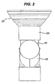
- a light according to a first embodiment of the present invention is shown in figures 1 to 4 , 6 and 7 .
- the light comprises a light source 50 mounted in a base unit 30.
- the light source comprises a 12V 100W halogen capsule.
- the light source is mounted in a parabolic reflector 55.
- the embodiment shown in figure 5 is the same as that shown in figures 1 to 4 , 6 and 7 , except that the light source 50 comprises a dichroic halogen bulb and no-parabolic reflector is present.
- a cone shaped deflector 10 is positioned within the path of a light beam emitted by the light source 50.
- the conical surface of the deflector 10 is reflective.
- the surface of the deflector closest to the light source may be coated in aluminium.
- the deflector comprises a high-temperature polycarbonate (PC) deflector cone having an aluminium shield attached to the surface of the cone closest to the light source. Both the PC deflector and the aluminium shield may further be coated with another thinner layer of aluminium.
- the deflector may be made from a thermally stable plastic such as polyphenylene sulfide (PPS).
- PPS polyphenylene sulfide
- the PPS deflector may further be coated in a thin aluminium layer.
- the reflector 20 Surrounding the cone-shaped deflector 10 is a reflector 20.
- the reflector 20 is bowl shaped and the inner surface of the reflector 20 is formed from a plurality of ring shaped facets 25.
- Each ring shaped facet 25 is formed from the surface of a paraboloid.
- Each ring shaped facet is formed from a paraboloid having a different focal distance. The focal distance of the rings decreases with distance from the light source.
- the reflector 20 is capable of being moved vertically relative to the base unit 30, light source 50 and deflector cone 10.
- the reflector 20 is positioned so as to rest upon an edge of an off-centre circular cam 40.
- the off-centre circular cam 40 is mounted on the base unit 30.
- the off-centre cam 40 may be driven by a motor 60 housed within the base unit 30.
- the light source 50 shines a beam directly on to the cone shaped deflector 10.
- the beam is reflected by the deflector 10 into a ring of light, which travels outwards from the deflector 10.
- the apex 15 and axis of the cone are pointing directly at the light source 50.
- the light reflected by the deflector 10 strikes the reflective ring-shaped facets 25 on the inside of the reflector 20 at a specific vertical level relative to the deflector 10. Therefore, vertically moving the reflector 20 upward relative to the deflector 10 results in the light being reflected by the reflective ring facets 25 further down the reflector 20.
- each ring-shaped facet is different, the angle at which light from the deflector is reflected by the ring facet will be different for each ring.
- the focal distance decreases with distance from the light source. Therefore light emanating from the deflector which strikes the facets furthest from the light source produces a wider beam angle than light which strikes the facets closest to the light source.
- the focal distance of the parabolas forming the ring facets in between the top and the bottom of the reflector 20 gradually increases from the top to the bottom.
- the reflector includes ten ring facets.
- the base unit 30 includes a motor 60 and an off-centre cam 40.
- the off-centre cam 40 rotates, the reflector 20 is pushed upward relative to the deflector 10 by the edge of the cam 40. As this occurs, the beam angle of the light emitted out of the reflector 20 is reduced. Furthermore, when the off-centre cam 40 rotates further and the reflector 20 moves downwards relative to the deflector 10, the beam angle of the light emitted out of the reflector 20 is increased.
- the cam leads to a cyclic motion such that the beam angle cycles between a maximum and a minimum.
- the cam 40 is positioned so that its circular front face is positioned vertically and parallel to a side of the base unit 30.
- the motor 60 is mounted on the base unit 30 via a motor plate 61. To ensure the cam 40 runs vertically and thus parallel to the surface of the base unit 30 to which it is attached, the motor plate 61 is mounted at an angle of 1 degrees back from the vertical.
- the base unit also includes a potentiometer 62 which acts as a dimmer switch, a transformer, and an on/off switch 64. Consequently, the lighting system can be plugged directly into the mains, without the need for a dimmer switch, an on/off switch or transformer on the power lead or a remote control.
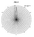
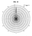
- Figures 8 to 12 are polar curves showing the intensity and angle at which light is distributed from the reflector of the lights shown in figures 1 to 7 .
- the angle of the beam increases from figure 8 through to figure 12 , as the reflector moves downward relative to the deflector. As the angle increases, the same amount of light is spread over a larger angle, and dispersed evenly over the area of the beam.
- the cone shaped deflector 10 is mounted on the base unit 30 by means of a wire frame 70, which functions to maintain its the position of the deflector cone 10 in the path of the light beam.
- Part of the wire frame 70 encircles the base of the deflector cone 10 and another part of the wire frame 70 acts as legs to space the cone 10 from the light source. Both ends of the wire frame 70 are rooted in the base unit 30.
- the cone shaped deflector 10 is injection-moulded with ribs or webs 75 for mounting the deflector on the base unit 30.
- the ribs or webs 75 function to maintain the position of the deflector cone 10 in the path of the light beam.
- the ribs or webs 75 act to space the cone 10 from the light source.
- the embodiment shown in figures 13 , 14 and 15 also includes a diffusor disc 80 formed from opal glass which is present to diffuse the light emitted from the lighting system in order to reduce side spill and give a more uniform distribution of light.
- the opal glass shown has an opal clarity of 60%.
- the lighting system may be provided with a ventilation pathway 95 that allows cool air to be drawn through the interior of the lighting system.
- the ventilation pathway is provided by machining or tooling vents 90 in various components of the system to allow air to be drawn through the system.
- vents 90 are formed in the base unit 30, and in the interior structure of the lighting system including in a bulb plate 92 and a guide tube 94.
Landscapes
- Engineering & Computer Science (AREA)
- General Engineering & Computer Science (AREA)
- Non-Portable Lighting Devices Or Systems Thereof (AREA)
- Materials For Medical Uses (AREA)
- Eye Examination Apparatus (AREA)
- Glass Compositions (AREA)
- Vessels And Coating Films For Discharge Lamps (AREA)
Claims (14)
- Beleuchtungssystem, das umfasst:eine Lichtquelle (50);einen Deflektor bzw. eine Ablenkplatte (10), die in dem Weg eines von der Lichtquelle (50) emittierten Lichtstrahls positioniert ist;einen Reflektor (20), der relativ zu dem Deflektor (10) beweglich ist; und gekennzeichnet durch:ein Antriebsmittel zum Bewegen des Reflektors (20) in einer periodischen Bewegung relativ zu dem Deflektor (10).
- Beleuchtungssystem nach Anspruch 1, wobei der Reflektor (20) aus einer Vielzahl von Ringen aus reflektierenden Facetten (25) ausgebildet ist, wobei jeder Ring aus der Oberfläche eines Paraboloids ausgebildet ist.
- Beleuchtungssystem nach Anspruch 2, wobei jeder der Vielzahl von Ringen (25) aus einem Paraboloid mit einer anderen Brennweite gebildet ist.
- Beleuchtungssystem nach Anspruch 3, wobei die Brennweite der Ringe (25) mit dem Abstand von der Lichtquelle abnimmt.
- Beleuchtungssystem nach Anspruch 4, wobei die Brennpunkte der Vielzahl von Ringen (25) entlang einer zentralen Achse des Reflektors (20) beabstandet sind.
- Beleuchtungssystem nach Anspruch 1, wobei das Antriebsmittel eine Nocke (40) in Verbindung mit dem Reflektor (20) umfasst, um den Reflektor (20) in einer periodischen Bewegung relativ zu dem Deflektor (10) zu bewegen, während die Nocke (40) gedreht wird.
- Beleuchtungssystem nach Anspruch 6, wobei die Nocke (40) eine exzentrische kreisförmige Nocke ist.
- Beleuchtungssystem nach einem der vorangehenden Ansprüche, wobei der Deflektor (10) kegelförmig ist.
- Beleuchtungssystem nach einem der vorangehenden Ansprüche, wobei der Apex bzw. Scheitel des Deflektorkegels (10) der Lichtquelle (50) zugewandt ist.
- Beleuchtungssystem nach einem der vorangehenden Ansprüche, wobei die Achse des Deflektorkegels (10) mit der Achse des Reflektors (20) zusammenfällt.
- Beleuchtungssystem nach einem der vorangehenden Ansprüche, wobei die Achse des Deflektorkegels (10) relativ zu der Achse des Reflektors (20) beweglich ist.
- Beleuchtungssystem nach einem der vorangehenden Ansprüche, das ferner einen Diffusor (80) umfasst.
- Beleuchtungssystem nach Anspruch 12, wobei der Diffusor (80) auf dem Deflektorkegel (10) montiert ist.
- Beleuchtungssystem nach einem der vorangehenden Ansprüche, wobei der Deflektorkegel (10) mit einer Vielzahl von Stützstegen (75) spritzgegossen ist, um den Deflektorkegel (10) in dem Weg des von der Lichtquelle (50) emittierten Lichts zu montieren.
Applications Claiming Priority (2)
| Application Number | Priority Date | Filing Date | Title |
|---|---|---|---|
| GB0610761A GB2438637A (en) | 2006-05-31 | 2006-05-31 | Active lighting system having automatically changing light effect. |
| PCT/GB2007/002006 WO2007138321A1 (en) | 2006-05-31 | 2007-05-31 | A light |
Publications (2)
| Publication Number | Publication Date |
|---|---|
| EP2021686A1 EP2021686A1 (de) | 2009-02-11 |
| EP2021686B1 true EP2021686B1 (de) | 2010-02-24 |
Family
ID=36694699
Family Applications (1)
| Application Number | Title | Priority Date | Filing Date |
|---|---|---|---|
| EP07733022A Active EP2021686B1 (de) | 2006-05-31 | 2007-05-31 | Lampe |
Country Status (8)
| Country | Link |
|---|---|
| US (1) | US8052309B2 (de) |
| EP (1) | EP2021686B1 (de) |
| JP (1) | JP2009539215A (de) |
| CN (1) | CN101454611B (de) |
| AT (1) | ATE458961T1 (de) |
| DE (1) | DE602007004974D1 (de) |
| GB (1) | GB2438637A (de) |
| WO (1) | WO2007138321A1 (de) |
Families Citing this family (5)
| Publication number | Priority date | Publication date | Assignee | Title |
|---|---|---|---|---|
| TW200912195A (en) * | 2007-09-05 | 2009-03-16 | Taiwan Network Comp & Amp Electronic Co Ltd | Light-spreading and energy-saving shade |
| KR101781424B1 (ko) | 2010-11-26 | 2017-09-26 | 서울반도체 주식회사 | 엘이디 조명기구 |
| CN102878443B (zh) * | 2011-07-15 | 2016-07-06 | 欧司朗股份有限公司 | 调焦单元和具有该调焦单元的光引擎和照明装置 |
| WO2015200664A2 (en) * | 2014-06-27 | 2015-12-30 | Garden Peninsulas, LLC | Lamp retrofitting assembly |
| US9989219B2 (en) * | 2016-10-14 | 2018-06-05 | David R. Hall | Light bulb with a motor |
Family Cites Families (42)
| Publication number | Priority date | Publication date | Assignee | Title |
|---|---|---|---|---|
| US1423253A (en) * | 1917-01-15 | 1922-07-18 | Willys Corp | Headlight |
| US1706836A (en) | 1923-10-09 | 1929-03-26 | Monogram Lens Corp | Adapter for headlight reflectors |
| US1545009A (en) * | 1924-07-12 | 1925-07-07 | Charles L Paine | Mushroom light |
| US1967342A (en) * | 1932-04-19 | 1934-07-24 | Ralph T Ross | Headlight deflector |
| US2059762A (en) * | 1936-01-24 | 1936-11-03 | Frank C Townsend | Antiglare device for vehicle lamps |
| US2275621A (en) * | 1940-09-10 | 1942-03-10 | Ibm | Illuminated dial |
| US2607839A (en) | 1949-02-02 | 1952-08-19 | Pyle National Co | Illumination apparatus for warning and signaling purposes and method of control |
| US3700883A (en) * | 1970-09-23 | 1972-10-24 | Gen Motors Corp | Faceted reflector for lighting unit |
| US3877171A (en) * | 1973-07-23 | 1975-04-15 | Mattel Inc | Flashlight amusement device |
| US4037096A (en) * | 1974-08-09 | 1977-07-19 | American Sterilizer Company | Illuminator apparatus using optical reflective methods |
| US4663696A (en) * | 1985-01-31 | 1987-05-05 | Koito Siesakusho Co., Ltd. | Dual purpose lamp assembly for use, for example, as a combined fog and cornering lamp on a motor vehicle |
| US5255110A (en) * | 1985-12-25 | 1993-10-19 | Canon Kabushiki Kaisha | Driving method for optical modulation device using ferroelectric liquid crystal |
| FR2664363B1 (fr) | 1990-07-03 | 1992-12-31 | Valeo Vision | Projecteur a plusieurs fonctions, en particulier pour vehicule automobile, adapte a ameliorer l'eclairement d'elements de signalisation routiere. |
| WO1992017733A1 (en) | 1991-04-03 | 1992-10-15 | Gte Products Corporation | Lamp and reflector assembly |
| US5272408A (en) * | 1991-05-09 | 1993-12-21 | Gte Products Corporation | Lamp and reflector assembly |
| US5104347A (en) * | 1991-04-15 | 1992-04-14 | Playskool, Inc. | Carousel mechanism |
| US5105347A (en) * | 1991-05-02 | 1992-04-14 | Ruud Lighting, Inc. | Bollard luminaire |
| JPH05120909A (ja) * | 1991-10-30 | 1993-05-18 | Asahi Glass Co Ltd | ランプ |
| US5367349A (en) * | 1993-11-17 | 1994-11-22 | Robert Zeiler | Amusement projector |
| JPH07192506A (ja) * | 1993-12-27 | 1995-07-28 | Koizumi Sangyo Kk | 照明器具 |
| DE4417695C2 (de) * | 1994-05-20 | 1998-01-29 | Reitter & Schefenacker Gmbh | Kraftfahrzeugleuchte |
| US5582479A (en) | 1995-03-01 | 1996-12-10 | Eppi Lighting, Inc. | Dual reflector high bay lighting system |
| US5803571A (en) * | 1995-10-20 | 1998-09-08 | Mcentyre; Rick | I-snoot |
| US5791768A (en) | 1997-04-17 | 1998-08-11 | Stingray Lighting, Inc. | Dual reflector lighting system |
| US5951139A (en) * | 1997-04-17 | 1999-09-14 | Steris Corporation | Surgical light with reflector-lamps and flat reflector panels |
| US6241366B1 (en) * | 1997-06-04 | 2001-06-05 | High End Systems, Inc. | Lighting system with diffusing dimmer |
| US6113252A (en) | 1998-02-17 | 2000-09-05 | Vari-Lite, Inc. | Architectural luminaries |
| DE29808427U1 (de) | 1998-05-09 | 1998-07-23 | Patent-Treuhand-Gesellschaft für elektrische Glühlampen mbH, 81543 München | Reflexionseinheit für Reflektorlampen und Beleuchtungssystem mit einer derartigen Reflexionseinheit |
| WO2001036871A1 (en) | 1999-11-18 | 2001-05-25 | Morpheus Technologies, Llc | Light projector |
| US6464373B1 (en) * | 2000-11-03 | 2002-10-15 | Twr Lighting, Inc. | Light emitting diode lighting with frustoconical reflector |
| US6568835B2 (en) * | 2001-03-23 | 2003-05-27 | Koninklijke Philips Electronics N.V. | Luminaire |
| US6637921B2 (en) * | 2001-09-28 | 2003-10-28 | Osram Sylvania Inc. | Replaceable LED bulb with interchangeable lens optic |
| BE1014501A5 (nl) | 2001-11-30 | 2003-11-04 | Mega Nv | Verlichtingstoestel. |
| JP4162935B2 (ja) * | 2002-07-04 | 2008-10-08 | 株式会社小糸製作所 | 車両用灯具 |
| US6837603B2 (en) * | 2003-04-22 | 2005-01-04 | Sergiy Komarynsky | Emergency taillight for vehicles, especially for motor vehicles |
| DE20320124U1 (de) * | 2003-12-24 | 2005-05-12 | Rössle & Wanner GmbH | Lampe |
| WO2006033032A1 (en) * | 2004-09-24 | 2006-03-30 | Koninklijke Philips Electronics N.V. | Illumination system |
| US20060092638A1 (en) * | 2004-10-28 | 2006-05-04 | Harwood Ronald P | Housing for intelligent lights |
| US7488084B2 (en) * | 2004-10-29 | 2009-02-10 | Pentair Water Pool And Spa, Inc. | Selectable beam lens for underwater light |
| DE102005007348A1 (de) * | 2005-02-17 | 2006-08-31 | Zumtobel Staff Gmbh | Strahlerleuchte mit variabler Lichtabstrahlcharakteristik |
| EP1920285A4 (de) * | 2005-07-28 | 2010-11-03 | Light Prescriptions Innovators | Linsenförmige optische freiformelemente und ihre anwendung auf kondensatoren und scheinwerfer |
| DE102006023120B4 (de) * | 2006-05-16 | 2010-10-14 | Auer Lighting Gmbh | Lichtreflektor mit definierter Konturenschärfe der von diesem erzeugten Lichtverteilung |
-
2006
- 2006-05-31 GB GB0610761A patent/GB2438637A/en not_active Withdrawn
-
2007
- 2007-05-31 AT AT07733022T patent/ATE458961T1/de not_active IP Right Cessation
- 2007-05-31 JP JP2009512669A patent/JP2009539215A/ja active Pending
- 2007-05-31 DE DE602007004974T patent/DE602007004974D1/de active Active
- 2007-05-31 WO PCT/GB2007/002006 patent/WO2007138321A1/en not_active Ceased
- 2007-05-31 EP EP07733022A patent/EP2021686B1/de active Active
- 2007-05-31 US US12/302,514 patent/US8052309B2/en active Active
- 2007-05-31 CN CN2007800196157A patent/CN101454611B/zh active Active
Also Published As
| Publication number | Publication date |
|---|---|
| US8052309B2 (en) | 2011-11-08 |
| WO2007138321A1 (en) | 2007-12-06 |
| GB0610761D0 (en) | 2006-07-12 |
| CN101454611A (zh) | 2009-06-10 |
| ATE458961T1 (de) | 2010-03-15 |
| US20090201682A1 (en) | 2009-08-13 |
| DE602007004974D1 (de) | 2010-04-08 |
| GB2438637A (en) | 2007-12-05 |
| EP2021686A1 (de) | 2009-02-11 |
| CN101454611B (zh) | 2011-04-27 |
| JP2009539215A (ja) | 2009-11-12 |
Similar Documents
| Publication | Publication Date | Title |
|---|---|---|
| JP5757883B2 (ja) | 発光装置及び照明器具 | |
| CN105431680B (zh) | 在照明目标区域中用于独立瞄准和遮断步骤的装置、方法和系统 | |
| US10415799B1 (en) | Dual output downlight fixture | |
| JP2008047541A (ja) | 照明装置 | |
| CN102844620A (zh) | 面照明器具和面照明装置 | |
| CA2794827C (en) | Hyperbolic ceiling-reflector for directional light sources | |
| JP2007012288A (ja) | 照明装置及び照明器具 | |
| JP2010129501A (ja) | 照明装置および照明器具 | |
| US9804321B1 (en) | LED optics for bulbs and luminaires | |
| US8052309B2 (en) | Lighting system with reflector that moves in a periodic manner | |
| US20150285460A1 (en) | Lighting Apparatus with Annular Segmented Reflector | |
| JP5302421B2 (ja) | 屋内照明装置および内部空間を照明する方法 | |
| JP2014150009A (ja) | 電球型照明装置 | |
| JP4711456B2 (ja) | ダウンライト | |
| JP2024117743A (ja) | 片側光源を伴う間接照明器具 | |
| EP3431868A1 (de) | Vorrichtung zur kadadioptrischen beleuchtung | |
| US20160109093A1 (en) | Lighting device, lighting kit and luminaire | |
| CN220205534U (zh) | 一种深防眩、精准控光且摆头角度清晰的射灯 | |
| CN218032996U (zh) | 一种照明灯具 | |
| CN222363811U (zh) | 一种多光源间接照明防止眩光的灯具 | |
| JP2009266546A (ja) | 照明器具 | |
| JP2025014653A (ja) | 照明器具 | |
| CN115523474A (zh) | 一种照明灯具 | |
| JP2022150134A (ja) | Led照明装置 | |
| JP2004265699A (ja) | 照明器具 |
Legal Events
| Date | Code | Title | Description |
|---|---|---|---|
| PUAI | Public reference made under article 153(3) epc to a published international application that has entered the european phase |
Free format text: ORIGINAL CODE: 0009012 |
|
| 17P | Request for examination filed |
Effective date: 20081215 |
|
| AK | Designated contracting states |
Kind code of ref document: A1 Designated state(s): AT BE BG CH CY CZ DE DK EE ES FI FR GB GR HU IE IS IT LI LT LU LV MC MT NL PL PT RO SE SI SK TR |
|
| AX | Request for extension of the european patent |
Extension state: AL BA HR MK RS |
|
| 17Q | First examination report despatched |
Effective date: 20090508 |
|
| GRAP | Despatch of communication of intention to grant a patent |
Free format text: ORIGINAL CODE: EPIDOSNIGR1 |
|
| DAX | Request for extension of the european patent (deleted) | ||
| GRAS | Grant fee paid |
Free format text: ORIGINAL CODE: EPIDOSNIGR3 |
|
| GRAA | (expected) grant |
Free format text: ORIGINAL CODE: 0009210 |
|
| RAP1 | Party data changed (applicant data changed or rights of an application transferred) |
Owner name: DYSON, JACOB |
|
| RIN1 | Information on inventor provided before grant (corrected) |
Inventor name: DYSON, JACOB |
|
| AK | Designated contracting states |
Kind code of ref document: B1 Designated state(s): AT BE BG CH CY CZ DE DK EE ES FI FR GB GR HU IE IS IT LI LT LU LV MC MT NL PL PT RO SE SI SK TR |
|
| REG | Reference to a national code |
Ref country code: GB Ref legal event code: FG4D |
|
| REG | Reference to a national code |
Ref country code: CH Ref legal event code: EP |
|
| REG | Reference to a national code |
Ref country code: IE Ref legal event code: FG4D |
|
| REF | Corresponds to: |
Ref document number: 602007004974 Country of ref document: DE Date of ref document: 20100408 Kind code of ref document: P |
|
| REG | Reference to a national code |
Ref country code: DE Ref legal event code: R096 Ref document number: 602007004974 Country of ref document: DE Effective date: 20100408 |
|
| REG | Reference to a national code |
Ref country code: NL Ref legal event code: VDEP Effective date: 20100224 |
|
| LTIE | Lt: invalidation of european patent or patent extension |
Effective date: 20100224 |
|
| PG25 | Lapsed in a contracting state [announced via postgrant information from national office to epo] |
Ref country code: IS Free format text: LAPSE BECAUSE OF FAILURE TO SUBMIT A TRANSLATION OF THE DESCRIPTION OR TO PAY THE FEE WITHIN THE PRESCRIBED TIME-LIMIT Effective date: 20100624 Ref country code: LT Free format text: LAPSE BECAUSE OF FAILURE TO SUBMIT A TRANSLATION OF THE DESCRIPTION OR TO PAY THE FEE WITHIN THE PRESCRIBED TIME-LIMIT Effective date: 20100224 Ref country code: PT Free format text: LAPSE BECAUSE OF FAILURE TO SUBMIT A TRANSLATION OF THE DESCRIPTION OR TO PAY THE FEE WITHIN THE PRESCRIBED TIME-LIMIT Effective date: 20100625 |
|
| PG25 | Lapsed in a contracting state [announced via postgrant information from national office to epo] |
Ref country code: LV Free format text: LAPSE BECAUSE OF FAILURE TO SUBMIT A TRANSLATION OF THE DESCRIPTION OR TO PAY THE FEE WITHIN THE PRESCRIBED TIME-LIMIT Effective date: 20100224 Ref country code: FI Free format text: LAPSE BECAUSE OF FAILURE TO SUBMIT A TRANSLATION OF THE DESCRIPTION OR TO PAY THE FEE WITHIN THE PRESCRIBED TIME-LIMIT Effective date: 20100224 Ref country code: SI Free format text: LAPSE BECAUSE OF FAILURE TO SUBMIT A TRANSLATION OF THE DESCRIPTION OR TO PAY THE FEE WITHIN THE PRESCRIBED TIME-LIMIT Effective date: 20100224 Ref country code: AT Free format text: LAPSE BECAUSE OF FAILURE TO SUBMIT A TRANSLATION OF THE DESCRIPTION OR TO PAY THE FEE WITHIN THE PRESCRIBED TIME-LIMIT Effective date: 20100224 Ref country code: PL Free format text: LAPSE BECAUSE OF FAILURE TO SUBMIT A TRANSLATION OF THE DESCRIPTION OR TO PAY THE FEE WITHIN THE PRESCRIBED TIME-LIMIT Effective date: 20100224 |
|
| PG25 | Lapsed in a contracting state [announced via postgrant information from national office to epo] |
Ref country code: CY Free format text: LAPSE BECAUSE OF FAILURE TO SUBMIT A TRANSLATION OF THE DESCRIPTION OR TO PAY THE FEE WITHIN THE PRESCRIBED TIME-LIMIT Effective date: 20100224 Ref country code: BE Free format text: LAPSE BECAUSE OF FAILURE TO SUBMIT A TRANSLATION OF THE DESCRIPTION OR TO PAY THE FEE WITHIN THE PRESCRIBED TIME-LIMIT Effective date: 20100224 Ref country code: SE Free format text: LAPSE BECAUSE OF FAILURE TO SUBMIT A TRANSLATION OF THE DESCRIPTION OR TO PAY THE FEE WITHIN THE PRESCRIBED TIME-LIMIT Effective date: 20100224 Ref country code: NL Free format text: LAPSE BECAUSE OF FAILURE TO SUBMIT A TRANSLATION OF THE DESCRIPTION OR TO PAY THE FEE WITHIN THE PRESCRIBED TIME-LIMIT Effective date: 20100224 Ref country code: RO Free format text: LAPSE BECAUSE OF FAILURE TO SUBMIT A TRANSLATION OF THE DESCRIPTION OR TO PAY THE FEE WITHIN THE PRESCRIBED TIME-LIMIT Effective date: 20100224 Ref country code: GR Free format text: LAPSE BECAUSE OF FAILURE TO SUBMIT A TRANSLATION OF THE DESCRIPTION OR TO PAY THE FEE WITHIN THE PRESCRIBED TIME-LIMIT Effective date: 20100525 Ref country code: ES Free format text: LAPSE BECAUSE OF FAILURE TO SUBMIT A TRANSLATION OF THE DESCRIPTION OR TO PAY THE FEE WITHIN THE PRESCRIBED TIME-LIMIT Effective date: 20100604 Ref country code: EE Free format text: LAPSE BECAUSE OF FAILURE TO SUBMIT A TRANSLATION OF THE DESCRIPTION OR TO PAY THE FEE WITHIN THE PRESCRIBED TIME-LIMIT Effective date: 20100224 |
|
| PG25 | Lapsed in a contracting state [announced via postgrant information from national office to epo] |
Ref country code: SK Free format text: LAPSE BECAUSE OF FAILURE TO SUBMIT A TRANSLATION OF THE DESCRIPTION OR TO PAY THE FEE WITHIN THE PRESCRIBED TIME-LIMIT Effective date: 20100224 Ref country code: CZ Free format text: LAPSE BECAUSE OF FAILURE TO SUBMIT A TRANSLATION OF THE DESCRIPTION OR TO PAY THE FEE WITHIN THE PRESCRIBED TIME-LIMIT Effective date: 20100224 Ref country code: BG Free format text: LAPSE BECAUSE OF FAILURE TO SUBMIT A TRANSLATION OF THE DESCRIPTION OR TO PAY THE FEE WITHIN THE PRESCRIBED TIME-LIMIT Effective date: 20100524 |
|
| PG25 | Lapsed in a contracting state [announced via postgrant information from national office to epo] |
Ref country code: MC Free format text: LAPSE BECAUSE OF NON-PAYMENT OF DUE FEES Effective date: 20100531 |
|
| PLBE | No opposition filed within time limit |
Free format text: ORIGINAL CODE: 0009261 |
|
| STAA | Information on the status of an ep patent application or granted ep patent |
Free format text: STATUS: NO OPPOSITION FILED WITHIN TIME LIMIT |
|
| PG25 | Lapsed in a contracting state [announced via postgrant information from national office to epo] |
Ref country code: DK Free format text: LAPSE BECAUSE OF FAILURE TO SUBMIT A TRANSLATION OF THE DESCRIPTION OR TO PAY THE FEE WITHIN THE PRESCRIBED TIME-LIMIT Effective date: 20100224 |
|
| 26N | No opposition filed |
Effective date: 20101125 |
|
| REG | Reference to a national code |
Ref country code: DE Ref legal event code: R097 Ref document number: 602007004974 Country of ref document: DE Effective date: 20101125 |
|
| PG25 | Lapsed in a contracting state [announced via postgrant information from national office to epo] |
Ref country code: IT Free format text: LAPSE BECAUSE OF NON-PAYMENT OF DUE FEES Effective date: 20100531 |
|
| PG25 | Lapsed in a contracting state [announced via postgrant information from national office to epo] |
Ref country code: MT Free format text: LAPSE BECAUSE OF FAILURE TO SUBMIT A TRANSLATION OF THE DESCRIPTION OR TO PAY THE FEE WITHIN THE PRESCRIBED TIME-LIMIT Effective date: 20100224 Ref country code: IE Free format text: LAPSE BECAUSE OF NON-PAYMENT OF DUE FEES Effective date: 20100531 |
|
| REG | Reference to a national code |
Ref country code: CH Ref legal event code: PL |
|
| PG25 | Lapsed in a contracting state [announced via postgrant information from national office to epo] |
Ref country code: LI Free format text: LAPSE BECAUSE OF NON-PAYMENT OF DUE FEES Effective date: 20110531 Ref country code: CH Free format text: LAPSE BECAUSE OF NON-PAYMENT OF DUE FEES Effective date: 20110531 |
|
| PG25 | Lapsed in a contracting state [announced via postgrant information from national office to epo] |
Ref country code: LU Free format text: LAPSE BECAUSE OF NON-PAYMENT OF DUE FEES Effective date: 20100531 Ref country code: HU Free format text: LAPSE BECAUSE OF FAILURE TO SUBMIT A TRANSLATION OF THE DESCRIPTION OR TO PAY THE FEE WITHIN THE PRESCRIBED TIME-LIMIT Effective date: 20100825 |
|
| PG25 | Lapsed in a contracting state [announced via postgrant information from national office to epo] |
Ref country code: TR Free format text: LAPSE BECAUSE OF FAILURE TO SUBMIT A TRANSLATION OF THE DESCRIPTION OR TO PAY THE FEE WITHIN THE PRESCRIBED TIME-LIMIT Effective date: 20100224 |
|
| REG | Reference to a national code |
Ref country code: DE Ref legal event code: R082 Ref document number: 602007004974 Country of ref document: DE Representative=s name: MUELLER-BORE & PARTNER PATENTANWAELTE PARTG MB, DE |
|
| REG | Reference to a national code |
Ref country code: DE Ref legal event code: R081 Ref document number: 602007004974 Country of ref document: DE Owner name: DYSON TECHNOLOGY LTD., MALMESBURY, GB Free format text: FORMER OWNER: DYSON, JACOB, LONDON, GB Effective date: 20150202 Ref country code: DE Ref legal event code: R082 Ref document number: 602007004974 Country of ref document: DE Representative=s name: MUELLER-BORE & PARTNER PATENTANWAELTE PARTG MB, DE Effective date: 20150202 |
|
| REG | Reference to a national code |
Ref country code: FR Ref legal event code: TP Owner name: DYSON TECHNOLOGY LIMITED, GB Effective date: 20150216 |
|
| REG | Reference to a national code |
Ref country code: GB Ref legal event code: 732E Free format text: REGISTERED BETWEEN 20150226 AND 20150304 |
|
| REG | Reference to a national code |
Ref country code: FR Ref legal event code: PLFP Year of fee payment: 10 |
|
| REG | Reference to a national code |
Ref country code: FR Ref legal event code: PLFP Year of fee payment: 11 |
|
| REG | Reference to a national code |
Ref country code: FR Ref legal event code: PLFP Year of fee payment: 12 |
|
| PGFP | Annual fee paid to national office [announced via postgrant information from national office to epo] |
Ref country code: IT Payment date: 20190626 Year of fee payment: 9 |
|
| PG25 | Lapsed in a contracting state [announced via postgrant information from national office to epo] |
Ref country code: IT Free format text: LAPSE BECAUSE OF NON-PAYMENT OF DUE FEES Effective date: 20200531 |
|
| P01 | Opt-out of the competence of the unified patent court (upc) registered |
Effective date: 20230514 |
|
| PGFP | Annual fee paid to national office [announced via postgrant information from national office to epo] |
Ref country code: DE Payment date: 20250423 Year of fee payment: 19 |
|
| PGFP | Annual fee paid to national office [announced via postgrant information from national office to epo] |
Ref country code: FR Payment date: 20250423 Year of fee payment: 19 |
|
| PGFP | Annual fee paid to national office [announced via postgrant information from national office to epo] |
Ref country code: GB Payment date: 20260312 Year of fee payment: 20 |