EP2021705B1 - System und verfahren zur einstellung eines gesteuerten expansionsventils - Google Patents
System und verfahren zur einstellung eines gesteuerten expansionsventils Download PDFInfo
- Publication number
- EP2021705B1 EP2021705B1 EP06771734A EP06771734A EP2021705B1 EP 2021705 B1 EP2021705 B1 EP 2021705B1 EP 06771734 A EP06771734 A EP 06771734A EP 06771734 A EP06771734 A EP 06771734A EP 2021705 B1 EP2021705 B1 EP 2021705B1
- Authority
- EP
- European Patent Office
- Prior art keywords
- temperature
- pressure
- evaporator
- enclosure
- refrigerant
- Prior art date
- Legal status (The legal status is an assumption and is not a legal conclusion. Google has not performed a legal analysis and makes no representation as to the accuracy of the status listed.)
- Ceased
Links
- 238000000034 method Methods 0.000 title claims description 54
- 238000005057 refrigeration Methods 0.000 claims description 70
- 239000003507 refrigerant Substances 0.000 claims description 69
- 238000001816 cooling Methods 0.000 claims description 23
- 230000007423 decrease Effects 0.000 claims description 11
- 238000010438 heat treatment Methods 0.000 claims 1
- 238000012544 monitoring process Methods 0.000 claims 1
- CURLTUGMZLYLDI-UHFFFAOYSA-N Carbon dioxide Chemical compound O=C=O CURLTUGMZLYLDI-UHFFFAOYSA-N 0.000 description 20
- 229910002092 carbon dioxide Inorganic materials 0.000 description 10
- 239000001569 carbon dioxide Substances 0.000 description 10
- 238000001704 evaporation Methods 0.000 description 7
- 239000007788 liquid Substances 0.000 description 7
- 230000008020 evaporation Effects 0.000 description 6
- 230000003247 decreasing effect Effects 0.000 description 5
- 239000012530 fluid Substances 0.000 description 5
- 229920006395 saturated elastomer Polymers 0.000 description 5
- 238000010586 diagram Methods 0.000 description 4
- 239000012080 ambient air Substances 0.000 description 3
- 230000001276 controlling effect Effects 0.000 description 3
- 239000012071 phase Substances 0.000 description 3
- 239000003570 air Substances 0.000 description 2
- 239000007791 liquid phase Substances 0.000 description 2
- 239000000203 mixture Substances 0.000 description 2
- 230000001105 regulatory effect Effects 0.000 description 2
- 239000011555 saturated liquid Substances 0.000 description 2
- 239000012808 vapor phase Substances 0.000 description 2
- ZAMOUSCENKQFHK-UHFFFAOYSA-N Chlorine atom Chemical compound [Cl] ZAMOUSCENKQFHK-UHFFFAOYSA-N 0.000 description 1
- CBENFWSGALASAD-UHFFFAOYSA-N Ozone Chemical compound [O-][O+]=O CBENFWSGALASAD-UHFFFAOYSA-N 0.000 description 1
- 230000002411 adverse Effects 0.000 description 1
- 229910052801 chlorine Inorganic materials 0.000 description 1
- 239000000460 chlorine Substances 0.000 description 1
- 230000006835 compression Effects 0.000 description 1
- 238000007906 compression Methods 0.000 description 1
- 230000001627 detrimental effect Effects 0.000 description 1
- 230000000694 effects Effects 0.000 description 1
- 239000000126 substance Substances 0.000 description 1
- 230000007704 transition Effects 0.000 description 1
- 230000005514 two-phase flow Effects 0.000 description 1
- 238000010792 warming Methods 0.000 description 1
Images

Classifications
-
- F—MECHANICAL ENGINEERING; LIGHTING; HEATING; WEAPONS; BLASTING
- F25—REFRIGERATION OR COOLING; COMBINED HEATING AND REFRIGERATION SYSTEMS; HEAT PUMP SYSTEMS; MANUFACTURE OR STORAGE OF ICE; LIQUEFACTION SOLIDIFICATION OF GASES
- F25B—REFRIGERATION MACHINES, PLANTS OR SYSTEMS; COMBINED HEATING AND REFRIGERATION SYSTEMS; HEAT PUMP SYSTEMS
- F25B49/00—Arrangement or mounting of control or safety devices
- F25B49/02—Arrangement or mounting of control or safety devices for compression type machines, plants or systems
-
- F—MECHANICAL ENGINEERING; LIGHTING; HEATING; WEAPONS; BLASTING
- F25—REFRIGERATION OR COOLING; COMBINED HEATING AND REFRIGERATION SYSTEMS; HEAT PUMP SYSTEMS; MANUFACTURE OR STORAGE OF ICE; LIQUEFACTION SOLIDIFICATION OF GASES
- F25B—REFRIGERATION MACHINES, PLANTS OR SYSTEMS; COMBINED HEATING AND REFRIGERATION SYSTEMS; HEAT PUMP SYSTEMS
- F25B9/00—Compression machines, plants or systems, in which the refrigerant is air or other gas of low boiling point
- F25B9/002—Compression machines, plants or systems, in which the refrigerant is air or other gas of low boiling point characterised by the refrigerant
- F25B9/008—Compression machines, plants or systems, in which the refrigerant is air or other gas of low boiling point characterised by the refrigerant the refrigerant being carbon dioxide
-
- F—MECHANICAL ENGINEERING; LIGHTING; HEATING; WEAPONS; BLASTING
- F25—REFRIGERATION OR COOLING; COMBINED HEATING AND REFRIGERATION SYSTEMS; HEAT PUMP SYSTEMS; MANUFACTURE OR STORAGE OF ICE; LIQUEFACTION SOLIDIFICATION OF GASES
- F25B—REFRIGERATION MACHINES, PLANTS OR SYSTEMS; COMBINED HEATING AND REFRIGERATION SYSTEMS; HEAT PUMP SYSTEMS
- F25B2309/00—Gas cycle refrigeration machines
- F25B2309/06—Compression machines, plants or systems characterised by the refrigerant being carbon dioxide
- F25B2309/061—Compression machines, plants or systems characterised by the refrigerant being carbon dioxide with cycle highest pressure above the supercritical pressure
-
- F—MECHANICAL ENGINEERING; LIGHTING; HEATING; WEAPONS; BLASTING
- F25—REFRIGERATION OR COOLING; COMBINED HEATING AND REFRIGERATION SYSTEMS; HEAT PUMP SYSTEMS; MANUFACTURE OR STORAGE OF ICE; LIQUEFACTION SOLIDIFICATION OF GASES
- F25B—REFRIGERATION MACHINES, PLANTS OR SYSTEMS; COMBINED HEATING AND REFRIGERATION SYSTEMS; HEAT PUMP SYSTEMS
- F25B2600/00—Control issues
- F25B2600/25—Control of valves
- F25B2600/2513—Expansion valves
-
- F—MECHANICAL ENGINEERING; LIGHTING; HEATING; WEAPONS; BLASTING
- F25—REFRIGERATION OR COOLING; COMBINED HEATING AND REFRIGERATION SYSTEMS; HEAT PUMP SYSTEMS; MANUFACTURE OR STORAGE OF ICE; LIQUEFACTION SOLIDIFICATION OF GASES
- F25B—REFRIGERATION MACHINES, PLANTS OR SYSTEMS; COMBINED HEATING AND REFRIGERATION SYSTEMS; HEAT PUMP SYSTEMS
- F25B2700/00—Sensing or detecting of parameters; Sensors therefor
- F25B2700/19—Pressures
- F25B2700/197—Pressures of the evaporator
-
- F—MECHANICAL ENGINEERING; LIGHTING; HEATING; WEAPONS; BLASTING
- F25—REFRIGERATION OR COOLING; COMBINED HEATING AND REFRIGERATION SYSTEMS; HEAT PUMP SYSTEMS; MANUFACTURE OR STORAGE OF ICE; LIQUEFACTION SOLIDIFICATION OF GASES
- F25B—REFRIGERATION MACHINES, PLANTS OR SYSTEMS; COMBINED HEATING AND REFRIGERATION SYSTEMS; HEAT PUMP SYSTEMS
- F25B2700/00—Sensing or detecting of parameters; Sensors therefor
- F25B2700/21—Temperatures
- F25B2700/2104—Temperatures of an indoor room or compartment
-
- F—MECHANICAL ENGINEERING; LIGHTING; HEATING; WEAPONS; BLASTING
- F25—REFRIGERATION OR COOLING; COMBINED HEATING AND REFRIGERATION SYSTEMS; HEAT PUMP SYSTEMS; MANUFACTURE OR STORAGE OF ICE; LIQUEFACTION SOLIDIFICATION OF GASES
- F25B—REFRIGERATION MACHINES, PLANTS OR SYSTEMS; COMBINED HEATING AND REFRIGERATION SYSTEMS; HEAT PUMP SYSTEMS
- F25B2700/00—Sensing or detecting of parameters; Sensors therefor
- F25B2700/21—Temperatures
- F25B2700/2117—Temperatures of an evaporator
- F25B2700/21175—Temperatures of an evaporator of the refrigerant at the outlet of the evaporator
Definitions
- the present invention relates generally to refrigeration systems. More particularly, the present invention relates to transcritical refrigeration systems configured to improve temperature pulldown after system start-up.
- the refrigerant In a typical refrigeration system that utilizes a circulating refrigerant, the refrigerant is circulated throughout a particular refrigerated area to remove heat from that area.
- the refrigerant enters the evaporator as a liquid or as a saturated mix of liquid and vapor and the liquid is evaporated (i.e., it boils off to pure vapor) as it absorbs heat from the refrigerated area. This process takes place at a refrigerant temperature somewhat below the temperature of the refrigerated area in order to facilitate heat transfer from the area to the refrigerant.
- the flow of refrigerant through the evaporator is normally regulated to maintain the temperature of the vapor exiting the evaporator at some fixed margin, or "superheat,” above the saturated temperature of the liquid-vapor mix. This assures that exactly enough refrigerant is circulated to match the heat load of the refrigerated area. Because the refrigerated area may not require constant cooling, the refrigeration system may be turned off for a period of time, thereby allowing the refrigerated area and the refrigerant to warm to a temperature at or near the ambient temperature. When the refrigerated area once again requires cooling, the refrigeration system is turned on, and the refrigerant will initially go through the process of evaporation at a temperature somewhat below the ambient temperature.
- Refrigerants containing chlorine have been phased out in most of the world due to their ozone destroying potential.
- Hydrofluorocarbons (HFCs) have been used as replacement refrigerants, but these refrigerants also have high global warming potential.
- "Natural" refrigerants, such as carbon dioxide have recently been proposed as replacement fluids.
- carbon dioxide has a low critical temperature, which causes the evaporator temperature and pressure to be above the critical point and in the supercritical region during start-up of the refrigeration system. When the refrigerant is at a temperature above the critical temperature, there are no separate liquid and vapor phases and so the normal process of evaporation cannot take place.
- the present invention is a system and method for controlling temperature pulldown of a refrigerated enclosure with a refrigeration system having a compressor, a heat rejecting heat exchanger, an expansion valve, and an evaporator.
- the method of the invention is as defined in claim 1.
- the system is as defined in claim 6.
- the method comprises circulating a refrigerant through the refrigeration system, sensing a parameter of the enclosure, determining a desired evaporator pressure based upon the parameter sensed, and adjusting the expansion valve as a function of the desired evaporator pressure.
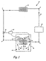
- FIG. 1 illustrates a schematic diagram of refrigeration system 20, which includes compressor 22, gas cooler 24, expansion valve 26, evaporator 28, evaporator sensor 30, enclosure sensor 31, and valve controller 32.
- Compressor 22 may comprise any type of compressor including, but not limited to, reciprocating, scroll, screw, rotary vane, standing vane, variable speed, hermetically sealed, and open drive compressors.
- Refrigeration system 20 is useful wherever a cooling source is needed, such as in temperature control units for buildings and automobiles. However, refrigeration system 20 will be described generically in reference to an "enclosure” that requires cooling.
- the "enclosure” may be an office area in a building or the food storage area in a refrigerated-type food transport vehicle.
- refrigerant path 34 is formed by connection of the various elements in refrigeration system 20.
- Refrigerant path 34 is created by a loop defined by the points 1, 2, 3, and 4.
- refrigerant is first compressed within compressor 22.
- the refrigerant then exits compressor 22 at high pressure and enthalpy (point 2) and is directed through gas cooler 24.
- the refrigerant loses heat in gas cooler 24, and exits gas cooler 24 at low enthalpy and high pressure (point 3).
- the refrigerant exiting gas cooler 24 is throttled in expansion valve 26.
- Expansion valve 26 is preferably an electronic expansion valve (EXV). After going through an expansion process within expansion valve 26 (point 4), the refrigerant is directed toward evaporator 28. After being heated in evaporator 28 (point 1), the refrigerant once again enters compressor 22, and the cycle repeats.
- EXV electronic expansion valve
- evaporator 28 of refrigeration system 20 is disposed within enclosure 36, which represents an area that requires cooling.
- a circulation element 38 such as a fan or blower, is coupled to enclosure 36 and is configured to direct streams of air 40 past evaporator 28 in an attempt to cool interior 42 of enclosure 36.
- temperature T1 of evaporator 28 will be approximately equal to temperature T2 of enclosure 36.
- temperatures T1 and T2 are substantially equivalent to the ambient air temperature outside enclosure 36.
- temperature T1 of evaporator 28 may be equal to the ambient temperature is not much of a concern because HFC refrigerants typically have high critical temperatures.
- refrigeration systems using HFC refrigerants tend to run "subcritical.” System operation and cooling capacity are relatively easy to control in a subcritical system due to the defined relationship between pressure and temperature in the subcritical region.
- temperature T1 of evaporator 28 may be equal or close to the ambient temperature is problematic because carbon dioxide has a relatively low critical temperature.
- the critical temperature of carbon dioxide is about 31 °C (87.8 degrees Fahrenheit). In warm climates, it is common for the ambient air temperature to exceed the critical temperature of carbon dioxide. When this occurs, temperatures T1 and T2 may exceed the critical temperature, thus resulting in a "supercritical" evaporator temperature.
- temperature T1 of evaporator 28 must be decreased to a subcritical temperature, i.e., a temperature that is below the critical temperature of the refrigerant. If temperature T1 remains supercritical during operation of refrigeration system 20, the system will have minimal cooling capacity and, as a result, it will be difficult or impossible to pull down the temperature of enclosure 36 much below the ambient temperature. This is especially detrimental when refrigeration system 20 is used in, for example, a refrigeration-type truck carrying perishable goods within enclosure 36.
- refrigeration system 20 it is critical that refrigeration system 20 is capable of pulling down temperature T2 of enclosure 36 to a low temperature within a short amount of time so that the perishable goods do not spoil.
- refrigeration system 20 is almost useless as a cooling source.
- the present invention provides a system and method for operating a refrigeration system to pull down an enclosure temperature while operating in either a subcritical or a supercritical cycle.
- expansion valve 26, evaporator sensor 30, enclosure sensor 31, and valve controller 32 operate together to enable sufficient enclosure temperature pulldown such that refrigeration system 20 remains useful as a cooling source even when operating in an environment wherein the ambient temperature is above the critical temperature of the refrigerant.
- Evaporator sensor 30 of refrigeration system 20 is coupled to evaporator 28, and is configured to sense a parameter within evaporator 28 and send a signal corresponding to the parameter to valve controller 32.
- the parameter sensed by evaporator sensor 30 is evaporator pressure, although other parameters (such as temperature) that may be sensed and used to deduce pressure are also contemplated.
- enclosure sensor 31 of refrigeration system 20 is coupled to enclosure 36, and is configured to sense a parameter within enclosure 36, such as temperature, and send a signal corresponding to the parameter to valve controller 32.
- Valve controller 32 may use a combination of, for example, the evaporator pressure, enclosure temperature, and the desired enclosure temperature setpoint to determine a desired evaporator pressure that will reduce the evaporator temperature to a subcritical temperature and enable pulldown of the enclosure temperature to the desired temperature setpoint.
- enclosure sensor 31 includes a temperature transducer such as a thermocouple, RTD (resistance temperature detector), or thermistor.
- Enclosure sensor 31 is configured to sense the temperature within interior 42 of enclosure 36 and send a signal to valve controller 32. Based upon the enclosure temperature, valve controller 32 determines the proper adjustment to the evaporator pressure necessary in order to attain the requisite heat transfer between evaporator 28 and enclosure 36 and achieve the desired enclosure setpoint temperature.
- expansion valve 26 is an electronic expansion valve (EXV) and evaporator sensor 30 includes a pressure transducer embedded in an evaporator tube to measure the refrigerant pressure.
- the pressure transducer provides a feedback signal to valve controller 32 which accordingly controls the movement of expansion valve 26.
- the EXV includes is a mechanical valve coupled to a stepper motor to control the opening and closing of the valve orifice.
- the stepper motor responds to the valve controller input by opening or closing the valve orifice as necessary.
- the pressure drop is modified by controlling the size of an orifice or flow restriction disposed within expansion valve 26.
- evaporator sensor 30 may additionally include a temperature transducer in order to determine superheat of the refrigerant vapor exiting evaporator 28 by comparing the temperature of the vapor to the saturated pressure within evaporator 28.
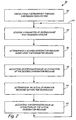
- FIG. 2 is a process flow diagram of a method 50 for controlling temperature pulldown of an enclosure with a refrigeration system. For purposes of example, method 50 will be discussed in reference to refrigeration system 20 of FIG. 1 .
- Method 50 begins at step 52 by circulating a refrigerant through a refrigeration system, such as refrigeration system 20.
- Method 50 continues at step 54 by sensing a parameter of an enclosure that requires cooling.
- the sensed parameter is the temperature of enclosure 36.
- a desired evaporator pressure is determined based upon the sensed parameter within the enclosure. Any parameter or combination of parameters that enables refrigeration system 20 to determine the desired evaporator pressure is within the intended scope of the present invention.
- the expansion valve is adjusted as a function of the desired evaporator pressure. In one embodiment, expansion valve 26 is adjusted to lower the evaporator pressure from a supercritical pressure to a subcritical pressure.
- step 58 After adjusting the expansion valve in step 58, an actual evaporator pressure is determined in step 60, such as with evaporator sensor 30. Finally, in step 62, the expansion valve is adjusted as a function of the actual evaporator pressure determined in step 60. It is important to note than in some instances, it may be necessary to perform steps 54-62 continuously or at defined intervals, as indicated by arrow 64, in order to achieve or maintain the desired enclosure setpoint temperature.
- steps comprising method 50 may be performed in a slightly different order.
- steps 60 and 62 may be omitted such that method 50 adjusts the expansion valve based solely on sensing the enclosure parameter and not on the actual evaporator pressure as well.
- method 50 it is possible to pull down the enclosure temperature in a refrigeration system that utilizes any type of refrigerant, operating in either subcritical or transcritical cycles.
- method 50 is particularly useful in conjunction with refrigeration systems configured to operate in a transcritical mode. As discussed previously, these types of systems typically run supercritical when used in a hot ambient temperature.
- the system and method of the present invention enables pulldown of the enclosure temperature even in hot ambient conditions.
- the present invention allows a refrigeration system to maintain the evaporator in a subcritical state even when operating in an environment above the critical temperature of the refrigerant being used.
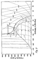
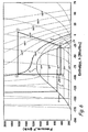
- FIG. 3 illustrates a graph relating pressure to enthalpy after start-up of refrigeration system 20 and prior to application of temperature pulldown method 50.
- refrigeration system 20 is configured to circulate carbon dioxide.
- carbon dioxide is used merely for purposes of example and not for limitation.
- the cycle in FIG. 3 assumes that the heat exchangers in refrigeration system 20 are ideal and that the pressure within evaporator 28 is held substantially constant.
- vapor dome. V is formed by a saturated liquid line and a saturated vapor line, and defines the state of the refrigerant at various points along the refrigeration cycle. Underneath vapor dome V, all states involve both liquid and vapor coexisting at the same time.
- critical point P is defined by the highest temperature and pressure where saturated liquid and saturated vapor coexist. In general, compressed liquids are located to the left of vapor dome V, while superheated vapors are located to the right of vapor dome V.
- critical point P As critical point P is approached, the properties of both liquid and gas become the same. Thus, above the critical point, there is only one phase. In particular, above its critical pressure, a substance cannot be separated into liquid and vapor phases.
- the temperature of the refrigerant remains constant at a specified pressure.
- the pressure and temperature of a refrigerant in the subcritical region are directly related.
- there is no specific relationship between temperature and pressure for example, the pressure within evaporator 28 (between points 4 and 1) remains around 1200 psia, but the temperature within evaporator 28 increases from about 85 degrees Fahrenheit (point 4) at the inlet of evaporator 28 to about 100 degrees Fahrenheit at the outlet (point 1). Therefore, outside of the subcritical region of vapor dome V, the relationship between temperature and pressure disappears.
- refrigerant path 34 is the loop defined by the points 1, 2, 3, and 4.
- the cycle begins in the main path at point 1, where the refrigerant is a low pressure, high enthalpy supercritical fluid prior to entering compressor 22. After compression within compressor 22, the refrigerant exits compressor 22 at high pressure and enthalpy, as shown by point 2. Then, as the refrigerant flows through gas cooler 24, enthalpy decreases while pressure remains constant, and the refrigerant exits as a cooler supercritical fluid. After exiting gas cooler 24, the refrigerant is then throttled in expansion valve 26, decreasing pressure as shown by point 4.
- the refrigerant is directed through evaporator 28, where it exits as a higher enthalpy supercritical fluid as shown by point 1.
- points 1, 2, 3, and 4 of the refrigeration cycle reside above the critical point P.
- the cycle is known as a "supercritical" cycle. In this supercritical region, the liquid and gas phases are no longer clearly distinguishable from each other, and the refrigerant remains a supercritical fluid throughout the entire cycle.
- the specific cooling capacity which is the measure of total cooling capacity divided by refrigerant mass flow, may typically be represented on a graph relating pressure to enthalpy by the length of the evaporation line.
- the specific cooling capacity of refrigeration system 20 after start-up is represented by the length of evaporation line L from point 4 to point 1.
- the specific cooling capacity determines the amount of heat transfer possible between a refrigeration system and an area to be cooled.
- the location of point 1 along evaporation line L is directly related to the temperature at point 1 which in turn is generally proportional to the temperature of the area to be cooled. Note that with an increase in pressure, the constant temperature lines near point 1 curve towards the left.
- both the enclosure temperature E1 of enclosure 36 and the ambient temperature A of the air outside enclosure 36 are about 37.8°C (100 degrees Fahrenheit).
- the desired temperature setpoint D of enclosure 36 is approximately -1.1°C (30 degrees Fahrenheit).
- refrigeration system 20 in order to cool enclosure 36 to desired setpoint D, refrigeration system 20 must have sufficient cooling capacity.
- temperature difference ⁇ T1 is about 8.3°C (15 degrees Fahrenheit) at point 4 and decreases rapidly to about 0°C (0 degrees Fahrenheit) at point 1. Due to the small temperature difference, the cooling capacity of the system is also small. Therefore, it is very difficult to pull down the temperature within enclosure 36 to desired temperature setpoint D (especially in a short period of time) without adjusting expansion valve 26, such as by method 50 as discussed above.
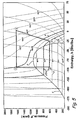
- FIG. 4 illustrates a graph relating pressure to enthalpy after start-up and a first application of temperature pulldown method 50.
- the adjustment of expansion valve 26 has caused the pressure of evaporator 28 to drop below vapor dome V and into the two-phase subcritical region of the vapor dome.
- the evaporator pressure has dropped from about 8274 kPa (1200 psia) to about 4826 kPa (700 psia), while the gas cooler pressure has remained constant at about 11031 kPa (1600 psia).
- points 2 and 3 of the refrigeration cycle remain above vapor dome V, while points 1 and 4 now reside below vapor dome V.
- the refrigeration cycle is known as a "transcritical" cycle.
- temperature difference ⁇ T2 is both known and constant at all times within vapor dome V.
- temperature and pressure are directly related. Therefore, in this subcritical region, the temperature of the refrigerant determines the pressure, and vice versa.
- a particular evaporator temperature may be achieved by adjusting expansion valve 26 to the evaporator pressure that corresponds with that temperature.
- method 50 allows refrigeration system 20 to constantly monitor and control the temperature difference between evaporator 28 and enclosure 36, and in turn, the cooling capacity of the system.
- adjusting the pressure drop caused by expansion valve 26 such that the evaporator pressure is now within the subcritical region results in an increased refrigeration capacity.
- This increased capacity is represented by the length of the evaporation line from point 4 to point 1.
- the main factor contributing to the increased refrigeration capacity is the large increase in the enthalpy at the evaporator exit temperature.
- the evaporator capacity has increased over the supercritical cycle of FIG. 3 even though the evaporator outlet temperature has remained the same.
- the ability to control the capacity has also improved by the transition from a supercritical cycle where there is no defined relationship between temperature and pressure to a transcritical cycle where the relationship between temperature and pressure is known.
- valve controller 32 must be programmed to determine the optimal pressure in evaporator 28 for a given enclosure temperature in order to maximize the net cooling capacity of the resulting refrigerant flow.
- enclosure temperature E2 is still substantially equivalent to ambient air temperature A after a first application of method 50. This results from the fact that the evaporator pressure has just dropped down into the subcritical region, and there has not been a sufficient amount of time for heat to transfer from enclosure 36 to the refrigerant flowing through evaporator 28. However, as will be seen in the following figures, the system and method of the present invention will result in a decrease in the enclosure temperature to the desired temperature setpoint D over time.
- FIG. 5 illustrates a graph relating pressure to enthalpy after a second application of temperature pulldown method 50.
- the controlled adjustment of expansion valve 26 has caused the pressure of evaporator 28 to drop to a lower pressure within vapor dome V.
- the evaporator pressure has dropped to about 3792 kPa (550 psia), while the gas cooler pressure has remained constant at about 11031 kPa (1600 psia).
- the refrigeration cycle is still operating as a transcritical cycle.
- the pressure difference between the high side gas cooler pressure and the low side evaporator pressure has increased.
- enclosure temperature E3 has dropped from about 37.8°C (100 degrees Fahrenheit) to about 15.6°C (60 degrees Fahrenheit). This decrease in enclosure temperature is a direct result of the controlled adjustment of expansion valve 26 according to temperature pulldown method 50. Without adjusting expansion valve 26 to decrease the evaporator pressure into a region of two-phase flow, it would not have been possible to achieve the decrease in the enclosure temperature under the present conditions.
- refrigeration system 20 By performing temperature pulldown method 50, refrigeration system 20 has been able to pull down enclosure temperature E3 closer toward desired temperature setpoint D, which is about -1.1°C (30 degrees Fahrenheit). However, since desired temperature setpoint D of enclosure 36 is lower than enclosure temperature E3 as shown in FIG. 5 , it may be necessary to decrease the evaporator pressure even further to lower the evaporator temperature to enable sufficient heat transfer. This may be accomplished by once again performing temperature pulldown method 50, as will be represented graphically in FIG. 6 .
- FIG. 6 illustrates a graph relating pressure to enthalpy for the final, steady state operation of the system where enclosure temperature E4 is substantially equivalent to desired temperature setpoint D after application of pulldown method 50 over a reasonably short period of time.
- the temperature of enclosure 36 has been pulled down from ambient temperature A in FIG. 3 to desired temperature setpoint D in FIG. 6 through controlled adjustment of expansion valve 26.
- the refrigeration system is said to be in steady state operation.
- it is no longer necessary to control expansion valve 26 as described previously in order to maintain enclosure temperature E4 at desired temperature setpoint D.
- refrigeration system 20 may continue to operate by application of a method similar to method 50 described above.
- refrigeration system 20 may alternatively use any number of other devices and methods to control the evaporator temperature during steady state operation of refrigeration system 20.
- refrigeration system 20 may include an additional sensor disposed near the outlet of evaporator 28 that is configured to sense the temperature of the refrigerant flowing through the outlet and control temperature of the refrigerant within the evaporator based upon this sensed value.
Landscapes
- Engineering & Computer Science (AREA)
- Physics & Mathematics (AREA)
- Mechanical Engineering (AREA)
- Thermal Sciences (AREA)
- General Engineering & Computer Science (AREA)
- Chemical & Material Sciences (AREA)
- Chemical Kinetics & Catalysis (AREA)
- Devices That Are Associated With Refrigeration Equipment (AREA)
Claims (10)
- Verfahren zum Steuern der Temperatur-Absenkung einer Umschließung (36) mit einem Kühlsystem (20), das einen Verdichter (22), einen wärmeabgebenden Wärmetauscher (24), ein Expansionsventil (26) und einen Verdampfer (28) aufweist, wobei das Verfahren aufweist:Zirkulieren eines Kältemittels durch das Kühlsystem;Erfassen eines Parameters der Umschließung;Bestimmen eines gewünschten Verdampfer-Drucks auf der Basis des erfassten Parameters; undEinstellen des Expansionsventils in Abhängigkeit von dem gewünschten Verdampfer-Druck.
- Verfahren nach Anspruch 1,
wobei der Parameter der Umschließung (36) die Temperatur ist. - Verfahren nach Anspruch 1, das ferner aufweist:Bestimmen eines tatsächlichen Verdampfer-Drucks im Inneren des Verdampfers (28); undEinstellen des Expansionsventils (26) in Abhängigkeit von dem tatsächlichen Verdampfer-Druck.
- Verfahren nach Anspruch 1,
wobei das Kältemittel in einem transkritischen Kältekreislauf arbeitet. - Verfahren nach Anspruch 1,
wobei der Schritt des Einstellens des Expansionsventils (26) in Abhängigkeit von dem gewünschten Verdampfer-Druck einen tatsächlichen Verdampfer-Druck von einem überkritischen Druck auf einen unterkritischen Druck vermindert. - Kühlsystem zum Kühlen einer Umschließung (36), aufweisend:einen Verdichter (22) zum Verdichten eines Kältemittels auf einen Gaskühler-Druck, wobei der Gaskühler-Druck ein überkritischer Druck ist;einen Gaskühler (24) zum Kühlen des Kältemittels;einen Verdampfer (28) zum Erwärmen des Kältemittels, wobei der Verdampfer einen Verdampfer-Druck hat;ein Expansionsventil (26), das zwischen dem Gaskühler und dem Verdampfer angeordnet ist und dazu ausgebildet ist, den Druck des Kältemittels von dem überkritischen Gaskühler-Druck auf einen gewünschten Verdampfer-Druck zu reduzieren, wobei der gewünschte Verdampfer-Druck ein unterkritischer Druck ist; undeinen Sensor zum Überwachen eines Umschließungsparameters, wobei das Kühlsystem dazu ausgebildet ist, den gewünschten Verdampfer-Druck auf der Basis der erfassten Umschließungsparameters zu bestimmen.
- Kühlsystem nach Anspruch 6,
wobei das Kältemittel in einem transkritischen Kältekreislauf arbeitet. - Kühlsystem nach Anspruch 6,
wobei der Umschließungsparameter die Umschließungstemperatur ist. - Kühlsystem nach Anspruch 6,
wobei der Sensor dazu ausgebildet ist, ein Signal an eine Ventilsteuerung (32) zu schicken, die den Umschließungsparameter angibt. - Kühlsystem nach Anspruch 9,
wobei die Ventilsteuerung (32) dazu ausgebildet ist, den Verdampfer-Druck auf der Basis des Umschließungsparameters einzustellen.
Applications Claiming Priority (1)
| Application Number | Priority Date | Filing Date | Title |
|---|---|---|---|
| PCT/US2006/021124 WO2007139554A1 (en) | 2006-06-01 | 2006-06-01 | System and method for controlled expansion valve adjustment |
Publications (3)
| Publication Number | Publication Date |
|---|---|
| EP2021705A1 EP2021705A1 (de) | 2009-02-11 |
| EP2021705A4 EP2021705A4 (de) | 2012-05-09 |
| EP2021705B1 true EP2021705B1 (de) | 2013-03-20 |
Family
ID=38778949
Family Applications (1)
| Application Number | Title | Priority Date | Filing Date |
|---|---|---|---|
| EP06771734A Ceased EP2021705B1 (de) | 2006-06-01 | 2006-06-01 | System und verfahren zur einstellung eines gesteuerten expansionsventils |
Country Status (4)
| Country | Link |
|---|---|
| US (1) | US8196421B2 (de) |
| EP (1) | EP2021705B1 (de) |
| CN (1) | CN101460790A (de) |
| WO (1) | WO2007139554A1 (de) |
Families Citing this family (22)
| Publication number | Priority date | Publication date | Assignee | Title |
|---|---|---|---|---|
| JP5198337B2 (ja) * | 2009-03-25 | 2013-05-15 | ホシザキ電機株式会社 | 自動製氷機 |
| US8011191B2 (en) | 2009-09-30 | 2011-09-06 | Thermo Fisher Scientific (Asheville) Llc | Refrigeration system having a variable speed compressor |
| US9097448B2 (en) * | 2009-10-12 | 2015-08-04 | Lg Electronics Inc. | Air conditioning system and method for controlling operation thereof |
| ES2764787T3 (es) | 2009-11-03 | 2020-06-04 | Carrier Corp | Reducción del pico de presión para sistemas de refrigerante que incorporan un intercambiador de calor de microcanales |
| DK2504641T3 (en) * | 2009-11-25 | 2019-02-25 | Carrier Corp | PROTECTION FROM LOW SUCTION PRESSURE IN COOLING STEAM COMPRESSION SYSTEM |
| WO2011139425A2 (en) * | 2010-04-29 | 2011-11-10 | Carrier Corporation | Refrigerant vapor compression system with intercooler |
| US9970696B2 (en) | 2011-07-20 | 2018-05-15 | Thermo King Corporation | Defrost for transcritical vapor compression system |
| FR2979419B1 (fr) * | 2011-08-30 | 2018-03-30 | Arkema France | Fluides de transfert de chaleur supercritiques a base de tetrafluoropropene |
| DE102012102041B4 (de) * | 2012-03-09 | 2019-04-18 | Audi Ag | Vorrichtung und Verfahren zur Vereisungsvermeidungsregelung für Wärmepumpenverdampfer |
| IN2014DN06976A (de) | 2012-04-17 | 2015-04-10 | Danfoss As | |
| EP3702184B1 (de) | 2012-09-20 | 2024-03-06 | Thermo King LLC | Elektrisches transportkühlmodul |
| US9718553B2 (en) | 2013-03-14 | 2017-08-01 | Rolls-Royce North America Technologies, Inc. | Adaptive trans-critical CO2 cooling systems for aerospace applications |
| EP2994385B1 (de) | 2013-03-14 | 2019-07-03 | Rolls-Royce Corporation | Adaptive transkritische co2-kühlsysteme für luft- und raumfahrtanwendungen |
| US10302342B2 (en) | 2013-03-14 | 2019-05-28 | Rolls-Royce Corporation | Charge control system for trans-critical vapor cycle systems |
| US10132529B2 (en) | 2013-03-14 | 2018-11-20 | Rolls-Royce Corporation | Thermal management system controlling dynamic and steady state thermal loads |
| US9676484B2 (en) | 2013-03-14 | 2017-06-13 | Rolls-Royce North American Technologies, Inc. | Adaptive trans-critical carbon dioxide cooling systems |
| US9657969B2 (en) | 2013-12-30 | 2017-05-23 | Rolls-Royce Corporation | Multi-evaporator trans-critical cooling systems |
| DE102015010593B4 (de) | 2015-08-11 | 2018-12-06 | Audi Ag | Betriebsverfahren für eine Kälteanlage und zugehörige Kälteanlage |
| EP3187796A1 (de) | 2015-12-28 | 2017-07-05 | Thermo King Corporation | Kaskadenwärmeübertragungssystem |
| KR101977385B1 (ko) * | 2017-07-25 | 2019-05-13 | 무진전자 주식회사 | 웨이퍼 건조 장치 및 방법 |
| US10982887B2 (en) * | 2018-11-20 | 2021-04-20 | Rheem Manufacturing Company | Expansion valve with selectable operation modes |
| WO2020116551A1 (en) * | 2018-12-07 | 2020-06-11 | Daikin Industries, Ltd. | Air-conditioner |
Family Cites Families (19)
| Publication number | Priority date | Publication date | Assignee | Title |
|---|---|---|---|---|
| US4197719A (en) * | 1976-01-29 | 1980-04-15 | Dunham-Bush, Inc. | Tri-level multi-cylinder reciprocating compressor heat pump system |
| US4254637A (en) * | 1979-10-19 | 1981-03-10 | Vilter Manufacturing Corporation | Refrigeration system with refrigerant cooling of compressor and its oil |
| NO890076D0 (no) | 1989-01-09 | 1989-01-09 | Sinvent As | Luftkondisjonering. |
| US5209072A (en) * | 1991-01-15 | 1993-05-11 | Westinghouse Electric Corp. | Refrigeration temperature control system |
| US5353602A (en) * | 1993-03-25 | 1994-10-11 | Calmac Manufacturing Corporation | Non-steady-state self-regulating intermittent flow thermodynamic system |
| US5522233A (en) * | 1994-12-21 | 1996-06-04 | Carrier Corporation | Makeup oil system for first stage oil separation in booster system |
| US6105378A (en) * | 1995-10-30 | 2000-08-22 | Shaw; David N. | Variable capacity vapor compression cooling system |
| JP3858297B2 (ja) * | 1996-01-25 | 2006-12-13 | 株式会社デンソー | 圧力制御弁と蒸気圧縮式冷凍サイクル |
| US6145326A (en) * | 1999-04-29 | 2000-11-14 | Systematic Refrigeration, Inc. | Forced oil cooling for refrigeration compressor |
| JP2001147048A (ja) * | 1999-11-19 | 2001-05-29 | Sanden Corp | 冷凍回路の過熱度制御装置 |
| US6321549B1 (en) * | 2000-04-14 | 2001-11-27 | Carrier Corporation | Electronic expansion valve control system |
| US6418735B1 (en) * | 2000-11-15 | 2002-07-16 | Carrier Corporation | High pressure regulation in transcritical vapor compression cycles |
| EP1369648A3 (de) * | 2002-06-04 | 2004-02-04 | Sanyo Electric Co., Ltd. | Kreislaufanlage mit überkritischem Kältemittel |
| US6626000B1 (en) * | 2002-10-30 | 2003-09-30 | Visteon Global Technologies, Inc. | Method and system for electronically controlled high side pressure regulation in a vapor compression cycle |
| US6826917B1 (en) * | 2003-08-01 | 2004-12-07 | York International Corporation | Initial pull down control for a multiple compressor refrigeration system |
| JP4613526B2 (ja) * | 2004-06-23 | 2011-01-19 | 株式会社デンソー | 超臨界式ヒートポンプサイクル装置 |
| EP1782001B1 (de) * | 2004-08-09 | 2016-11-30 | Carrier Corporation | Flashgas-entfernung aus einem sammler in einem kältekreislauf |
| US7178362B2 (en) * | 2005-01-24 | 2007-02-20 | Tecumseh Products Cormpany | Expansion device arrangement for vapor compression system |
| DE102005009173A1 (de) * | 2005-02-17 | 2006-08-24 | Bitzer Kühlmaschinenbau Gmbh | Kälteanlage |
-
2006
- 2006-06-01 EP EP06771734A patent/EP2021705B1/de not_active Ceased
- 2006-06-01 WO PCT/US2006/021124 patent/WO2007139554A1/en not_active Ceased
- 2006-06-01 CN CN200680054818.5A patent/CN101460790A/zh active Pending
- 2006-06-01 US US12/308,015 patent/US8196421B2/en not_active Expired - Fee Related
Also Published As
| Publication number | Publication date |
|---|---|
| EP2021705A4 (de) | 2012-05-09 |
| EP2021705A1 (de) | 2009-02-11 |
| WO2007139554A1 (en) | 2007-12-06 |
| US8196421B2 (en) | 2012-06-12 |
| US20090241566A1 (en) | 2009-10-01 |
| CN101460790A (zh) | 2009-06-17 |
Similar Documents
| Publication | Publication Date | Title |
|---|---|---|
| US8196421B2 (en) | System and method for controlled expansion valve adjustment | |
| US9951975B2 (en) | Carbon dioxide refrigerant vapor compression system | |
| EP2417406B1 (de) | Kühlungsdampf-kompressionssystem mit heissgasumleitung | |
| DK2147264T3 (en) | Refrigerant vapor compression system | |
| US8671703B2 (en) | Refrigerant vapor compression system with flash tank economizer | |
| JP5196452B2 (ja) | 充填量管理を備えた遷臨界冷媒蒸気圧縮システム | |
| EP2737264B1 (de) | Startlogik für eine kälteanlage | |
| CN102667372B (zh) | 用于制冷剂蒸汽压缩系统的低吸入压力保护 | |
| CN101910750A (zh) | 制冷剂蒸汽压缩系统的容量调节 | |
| US20100023166A1 (en) | Free-cooling limitation control for air conditioning systems | |
| US10359222B2 (en) | Controller for a vapour compression system and a method for controlling a vapour compression system | |
| HK1133917A (en) | System and method for controlled expansion valve adjustment | |
| JP6256834B2 (ja) | 自動販売機 | |
| HK1168416A (en) | Refrigerant vapor compression system with hot gas bypass | |
| HK1154282B (en) | Carbon dioxide refrigerant vapor compression system | |
| HK1138360B (en) | Free-cooling limitation control for air conditioning systems | |
| HK1142389B (en) | Refrigerant vapor compression system with flash tank economizer |
Legal Events
| Date | Code | Title | Description |
|---|---|---|---|
| PUAI | Public reference made under article 153(3) epc to a published international application that has entered the european phase |
Free format text: ORIGINAL CODE: 0009012 |
|
| 17P | Request for examination filed |
Effective date: 20081126 |
|
| AK | Designated contracting states |
Kind code of ref document: A1 Designated state(s): AT BE BG CH CY CZ DE DK EE ES FI FR GB GR HU IE IS IT LI LT LU LV MC NL PL PT RO SE SI SK TR |
|
| AX | Request for extension of the european patent |
Extension state: AL BA HR MK YU |
|
| RBV | Designated contracting states (corrected) |
Designated state(s): DE ES FR GB IT |
|
| REG | Reference to a national code |
Ref country code: DE Ref legal event code: R079 Ref document number: 602006035199 Country of ref document: DE Free format text: PREVIOUS MAIN CLASS: F25B0041040000 Ipc: F25B0049020000 |
|
| A4 | Supplementary search report drawn up and despatched |
Effective date: 20120410 |
|
| RIC1 | Information provided on ipc code assigned before grant |
Ipc: F25B 9/00 20060101ALI20120402BHEP Ipc: F25B 49/02 20060101AFI20120402BHEP |
|
| DAX | Request for extension of the european patent (deleted) | ||
| GRAP | Despatch of communication of intention to grant a patent |
Free format text: ORIGINAL CODE: EPIDOSNIGR1 |
|
| GRAS | Grant fee paid |
Free format text: ORIGINAL CODE: EPIDOSNIGR3 |
|
| GRAA | (expected) grant |
Free format text: ORIGINAL CODE: 0009210 |
|
| AK | Designated contracting states |
Kind code of ref document: B1 Designated state(s): DE ES FR GB IT |
|
| REG | Reference to a national code |
Ref country code: GB Ref legal event code: FG4D |
|
| REG | Reference to a national code |
Ref country code: DE Ref legal event code: R096 Ref document number: 602006035199 Country of ref document: DE Effective date: 20130516 |
|
| PG25 | Lapsed in a contracting state [announced via postgrant information from national office to epo] |
Ref country code: ES Free format text: LAPSE BECAUSE OF FAILURE TO SUBMIT A TRANSLATION OF THE DESCRIPTION OR TO PAY THE FEE WITHIN THE PRESCRIBED TIME-LIMIT Effective date: 20130701 |
|
| PLBE | No opposition filed within time limit |
Free format text: ORIGINAL CODE: 0009261 |
|
| STAA | Information on the status of an ep patent application or granted ep patent |
Free format text: STATUS: NO OPPOSITION FILED WITHIN TIME LIMIT |
|
| 26N | No opposition filed |
Effective date: 20140102 |
|
| PG25 | Lapsed in a contracting state [announced via postgrant information from national office to epo] |
Ref country code: IT Free format text: LAPSE BECAUSE OF FAILURE TO SUBMIT A TRANSLATION OF THE DESCRIPTION OR TO PAY THE FEE WITHIN THE PRESCRIBED TIME-LIMIT Effective date: 20130320 |
|
| REG | Reference to a national code |
Ref country code: DE Ref legal event code: R097 Ref document number: 602006035199 Country of ref document: DE Effective date: 20140102 |
|
| REG | Reference to a national code |
Ref country code: FR Ref legal event code: PLFP Year of fee payment: 11 |
|
| REG | Reference to a national code |
Ref country code: FR Ref legal event code: PLFP Year of fee payment: 12 |
|
| REG | Reference to a national code |
Ref country code: DE Ref legal event code: R082 Ref document number: 602006035199 Country of ref document: DE Representative=s name: SCHMITT-NILSON SCHRAUD WAIBEL WOHLFROM PATENTA, DE |
|
| PGFP | Annual fee paid to national office [announced via postgrant information from national office to epo] |
Ref country code: GB Payment date: 20170526 Year of fee payment: 12 Ref country code: DE Payment date: 20170522 Year of fee payment: 12 Ref country code: FR Payment date: 20170523 Year of fee payment: 12 |
|
| REG | Reference to a national code |
Ref country code: DE Ref legal event code: R119 Ref document number: 602006035199 Country of ref document: DE |
|
| GBPC | Gb: european patent ceased through non-payment of renewal fee |
Effective date: 20180601 |
|
| PG25 | Lapsed in a contracting state [announced via postgrant information from national office to epo] |
Ref country code: DE Free format text: LAPSE BECAUSE OF NON-PAYMENT OF DUE FEES Effective date: 20190101 Ref country code: GB Free format text: LAPSE BECAUSE OF NON-PAYMENT OF DUE FEES Effective date: 20180601 Ref country code: FR Free format text: LAPSE BECAUSE OF NON-PAYMENT OF DUE FEES Effective date: 20180630 |