EP2021707B1 - Réfrigérateur et/ou congélateur - Google Patents
Réfrigérateur et/ou congélateur Download PDFInfo
- Publication number
- EP2021707B1 EP2021707B1 EP07725516.4A EP07725516A EP2021707B1 EP 2021707 B1 EP2021707 B1 EP 2021707B1 EP 07725516 A EP07725516 A EP 07725516A EP 2021707 B1 EP2021707 B1 EP 2021707B1
- Authority
- EP
- European Patent Office
- Prior art keywords
- connecting element
- refrigerator
- bearing block
- freezer according
- inner container
- Prior art date
- Legal status (The legal status is an assumption and is not a legal conclusion. Google has not performed a legal analysis and makes no representation as to the accuracy of the status listed.)
- Not-in-force
Links
Images



Classifications
-
- F—MECHANICAL ENGINEERING; LIGHTING; HEATING; WEAPONS; BLASTING
- F25—REFRIGERATION OR COOLING; COMBINED HEATING AND REFRIGERATION SYSTEMS; HEAT PUMP SYSTEMS; MANUFACTURE OR STORAGE OF ICE; LIQUEFACTION SOLIDIFICATION OF GASES
- F25D—REFRIGERATORS; COLD ROOMS; ICE-BOXES; COOLING OR FREEZING APPARATUS NOT OTHERWISE PROVIDED FOR
- F25D23/00—General constructional features
-
- F—MECHANICAL ENGINEERING; LIGHTING; HEATING; WEAPONS; BLASTING
- F25—REFRIGERATION OR COOLING; COMBINED HEATING AND REFRIGERATION SYSTEMS; HEAT PUMP SYSTEMS; MANUFACTURE OR STORAGE OF ICE; LIQUEFACTION SOLIDIFICATION OF GASES
- F25D—REFRIGERATORS; COLD ROOMS; ICE-BOXES; COOLING OR FREEZING APPARATUS NOT OTHERWISE PROVIDED FOR
- F25D23/00—General constructional features
- F25D23/02—Doors; Covers
-
- F—MECHANICAL ENGINEERING; LIGHTING; HEATING; WEAPONS; BLASTING
- F25—REFRIGERATION OR COOLING; COMBINED HEATING AND REFRIGERATION SYSTEMS; HEAT PUMP SYSTEMS; MANUFACTURE OR STORAGE OF ICE; LIQUEFACTION SOLIDIFICATION OF GASES
- F25D—REFRIGERATORS; COLD ROOMS; ICE-BOXES; COOLING OR FREEZING APPARATUS NOT OTHERWISE PROVIDED FOR
- F25D23/00—General constructional features
- F25D23/06—Walls
- F25D23/065—Details
-
- E—FIXED CONSTRUCTIONS
- E05—LOCKS; KEYS; WINDOW OR DOOR FITTINGS; SAFES
- E05Y—INDEXING SCHEME ASSOCIATED WITH SUBCLASSES E05D AND E05F, RELATING TO CONSTRUCTION ELEMENTS, ELECTRIC CONTROL, POWER SUPPLY, POWER SIGNAL OR TRANSMISSION, USER INTERFACES, MOUNTING OR COUPLING, DETAILS, ACCESSORIES, AUXILIARY OPERATIONS NOT OTHERWISE PROVIDED FOR, APPLICATION THEREOF
- E05Y2900/00—Application of doors, windows, wings or fittings thereof
- E05Y2900/30—Application of doors, windows, wings or fittings thereof for domestic appliances
- E05Y2900/31—Application of doors, windows, wings or fittings thereof for domestic appliances for refrigerators
-
- F—MECHANICAL ENGINEERING; LIGHTING; HEATING; WEAPONS; BLASTING
- F25—REFRIGERATION OR COOLING; COMBINED HEATING AND REFRIGERATION SYSTEMS; HEAT PUMP SYSTEMS; MANUFACTURE OR STORAGE OF ICE; LIQUEFACTION SOLIDIFICATION OF GASES
- F25D—REFRIGERATORS; COLD ROOMS; ICE-BOXES; COOLING OR FREEZING APPARATUS NOT OTHERWISE PROVIDED FOR
- F25D2323/00—General constructional features not provided for in other groups of this subclass
- F25D2323/02—Details of doors or covers not otherwise covered
- F25D2323/024—Door hinges
Definitions
- the invention relates to a refrigerator and / or freezer with a body, in which at least one inner container for receiving refrigerated and / or frozen food is arranged, as well as with at least one bearing block for supporting one or more doors, by means of which the body is closable, wherein a cross-connection element is present, which extends in a region between two walls of the body.
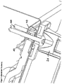
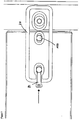
- FIG. 1 shows such an arrangement known from the prior art, in which the bearing block by the reference numeral 20, the fastening screws by the reference numeral 100, a portion of the side wall by the reference numeral 40 and the inner container by the reference numeral 10 is characterized.
- the FR 1 362 178 A relates to a refrigerator whose side walls can be plugged by means of a Ansteckmechanismus on an inner container.
- the citation FR 2 365 087 A discloses a household refrigerator with a closable by a door heat-insulated housing, which has a surrounded at its door opening by a flange-like edge inner container and side wall panels.
- a bearing block For storage of a door at least one bearing block is provided, which is connected via a screw connection with at least one side wall.
- the DE 30 02 512 A1 relates to a refrigerator housing with a cross section in the form of an inverted U and a substantially square bottom. Further, a central cross member is provided that connects at least two side walls of the housing together. A conclusion piece, that for the storage of a device door is suitable, may engage with an inwardly directed flange with the outer housing part.
- the WO 2007/062924 A1 (In the prior art under Article 54 (3) EPC) relates to a refrigerator or freezer whose housing is provided with a reinforcing frame to which a door is hinged hinges.
- the present invention has the object of developing a refrigerator or freezer of the type mentioned in that the possibility is opened to realize a high accuracy in the assembly of the bearing block or the doors and / or said prints from the foaming core in Inner container to avoid.
- the bearing block is fixed to a component directly connected to the cross-connection member, wherein the component is at least one connecting element which connects the cross-connecting element and the inner container with one or more walls of the body of the device, and wherein the connecting element a Component has or communicates with this, are arranged in the fastening means for mounting the bearing block.
- the bearing block is mounted on a component connected to the cross-connection element, which opens the possibility that the container is arranged floating, that is not determined by the fastening screw (s) of the bearing block, although such a configuration is also included in the invention.
- the inner container is taken up in a floating manner and is not fixed by the fastening elements, by means of which the bearing block is fastened to the carcass.
- said cross-connection element is by means of the connecting element with the walls z. B. with the side walls of the body of the device in connection . It is conceivable, for example by means of the connecting element to realize a fixed connection between the wall and cross-connection, which also allows the realization of high accuracy in the assembly of the bearing block or the assembly of the doors and the floating receptacle of the inner container.
- a connecting element may be provided, by means of which the transverse connecting element is connected to the inner container.
- the two mentioned connecting elements can be one and the same component.
- the above walls may, for example, to side walls, partitions of refrigerators or freezers, such. B. Freezings act.
- the connecting element comprises or is connected to a component, for example a plate, in which e.g. Tapped holes or other fastening means for mounting the bearing block are arranged.
- the cross-connection element is locked to the one or more connecting elements by means of a latching or clamping connection.
- one or more walls for. B. both side walls of the body of the device via a latching or clamping connection with the connecting element in connection.
- the inner container is also connected to the connecting element via a latching or clamping connection.
- the connecting element is latched to the cross-connection element, further serves to lock the inner container and is finally further with the wall or walls, for. B. side walls, the body of the device locked.
- the connecting element may further comprise a mounting plate or other component, the / has threaded holes in which mounting screws are added for the bearing block.
- the connecting element may have two elements which are connected to one another and can pivot relative to one another by means of a hinge, preferably by means of a film hinge, between which a portion of the inner container is accommodated in the mutually pivoted state of the elements.
- the device comprises means by means of which the bearing block can be fixed in a preferred position. In this way it is possible to choose the mounting position of the bearing block uniformly and thus to ensure matching positions of the doors.
- the means may for example be formed by a spring or by a screw, by means of which the bearing block can be fixed in a "zero position", but further allow the adjustability of the bearing block.
- the means may be formed by one or more resilient tabs, which are arranged on the connecting element or on another component.
- the means may also be formed by a screw which fixes the bearing block relative to the cross-connection element.
- the means are formed by a screw which is located in a threaded bore of the bearing block and which is arranged such that it acts on a fastening screw, by means of which the bearing block is fixed to the device.
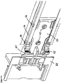
- Figure 2.1 shows the hereinafter referred to as a corner connecting member 60, that the cross-connecting element 30 connects to the inner container and with a side wall of the device.
- the cross-connection element 30 extends for example at the height between two superimposed compartments of the device over the entire width or a substantial part of the width of the device and is connected at its two end regions with one of the corner connecting elements 60 in connection.
- the cross-connection element 30 extends between the side walls of the device, for example, between a freezer and a cooling compartment of the device.
- the transverse connecting element 30 has openings at its two ends, in which latching hooks 66 of the corner connecting element 60 engage, as shown in FIG Figure 2.1 is shown.
- the corner connecting element 60 is pushed laterally in the direction of the arrow into grooves in the transverse connecting element 30 until the latching hooks 66 of the corner connecting element 60 engage in corresponding recesses of the transverse connecting element 30, as shown in FIG Figure 2.1 is shown.
- the corner connecting element 60 further has latching hooks 65 for the side wall of the device still to be mounted.
- the corner connector 60 furthermore has a fastening plate 50 made of metal, which is connected to it by a latching connection, for example, which has two threaded bores 52 arranged next to one another, as is likewise apparent Figure 2.1 evident.
- the arrow according to Figure 2.1 shows the insertion direction of the corner connecting element 60 in the arranged on the top and bottom of the cross-connecting element 30 grooves.
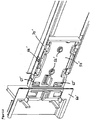
- Figure 2.2 shows the arrangement according to Figure 2.1 in another embodiment. Identical or functionally identical parts are marked with the same reference numerals with "'" as in FIG Figure 2.1 ,
- the corner connecting element 60 consists of the film hinge 62 and two elements 64 which are pivotable about the hinge 62 relative to each other.
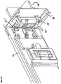
- the element 64 of the corner connecting element 60 which is not in communication with the inner container 10 is pivoted by 180 °, as indicated by the arrow in FIG Figure 3.1 is shown until it rests against the other side of the inner container 10, so that the two elements 64 of the Eckharmsimplantations 60 are substantially parallel to each other.
- the folded position is secured by latching hooks 67, which engage either with the inner container 10 or with the other of the elements 64 of the corner connecting element 60. In this way, the inner container 10 is fixed between the elements 64 of the corner connecting element.
- the side wall 40 is locked without play with the latching hooks 65 of the corner connecting element 60.
- the corner connecting element 60 thus serves to connect the transverse connecting element 30, side wall 40 and inner container 10.
- Figure 3.2 shows the arrangement according to Figure 3.1 with the in Figure 2.2 , illustrated corner connecting element. Identical or functionally identical parts are marked with the same reference numerals with "'" as in FIG Figure 3.1 ,
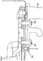
- FIG. 4 shows the arrangement with mounted bearing block 20 in a sectional view.
- the reference numeral 40 denotes a side wall, which is free of play with the corner connecting element 60 by means of said locking hooks 65.
- the inner container 10 is received between two elements 64 of the corner connecting element 60 and has in the in FIG. 4 illustrated embodiment game to the inner container 10, which is indicated by the reference numeral 200.
- the latched with the corner connecting element 60 transverse connecting element 30 has on its front side bores through which fixing screws are guided, which fix the bearing block 20 to the device. These mounting screws continue through the FIG. 2 apparent threaded bores 52 of the plate 50, which is in communication with the corner connecting element 60.
- Reference numeral 300 in FIG. 4 indicates a spout, which serves to perform the frame heater 310 through the inner container.
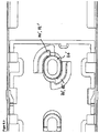
- Figure 5.1 shows in a view from behind a section of the corner connecting element 60 without mounting plate. From this view, it can be seen that the corner connecting element 60 has a recess in which the spring 70, which is formed by the two tabs 72. These two tabs 72 are bendable radially outwardly, as in Figure 5.1 indicated by arrows.
- Figure 5.2 indicates the situation in which the bearing block 20 is fixed via positive engagement in the zero position.
- the tabs 72 of the spring 70 hold the bearing block 20, of which in Figure 5.1, 5.2 a in the recess of the corner connecting element 60th shown approach is apparent in the zero position.
- Figure 5.1, 5.2 shows the executed as an elongated hole bore of the bearing block 20 through which a fastening screw is guided in the assembled state, the external thread meshes with the internal thread of the threaded bore 52 of the plate 50 which in Figure 5.1, 5.2 is not shown and connects to the side facing the viewer to the corner connector 60.
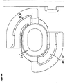
- the Figures 5.3 and 5.4 show an arrangement with diametrically opposed springs 70 'with spring tabs 72, between which the bearing block 20' is added.
- FIG. 6 shows an alternative possibility for realizing a preferred position, that is, a zero position of the bearing block 20.
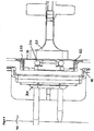
- an adjusting screw 82 is provided, which is guided through a corresponding bore in the transverse connecting element 30, as shown in FIG. 6 is shown.
- the fastening screws 100 are used for mounting the bearing block 20 on the mounting plate 50 in which said threaded bores 52 are located.
- FIG. 6 is located in the bearing block 20 for receiving the adjusting screw 82 has a threaded bore, via which the adjusting screw 82 can be screwed out of the fixing hole in the cross-connecting element 30 or screwed into this. If the bearing block 20 are to be adjusted, said adjusting screw 82 must be screwed out of the bearing block.
- FIG. 7 shows a further possibility for the realization of a bearing block with zero position, in which the adjusting screw 84 is provided frontally.
- the set screw thus does not run parallel to the fastening screws, as this in FIG. 6 the case is vertical.
- FIG. 7 shows the arrangement in a sectional view, wherein the reference numeral 100, the fastening screws and the reference numeral 84 represents the adjustment screw. Perpendicular to the oblong holes for receiving the fastening screws 100 extends a threaded bore in a lateral region of the bearing block such that this threaded hole communicates with one of the slots for receiving the fastening screw 100.
- the adjusting screw 84 is screwed until it rests in its end on the shaft of the fastening screw 100, as shown in FIG. 7 is shown.
- the bearing block 20 is placed with the screw 84, for example, pressed outward and the mounting screws are screwed.
- the screw 84 it is necessary to adjust the screw 84.
- the assembled door presses the adjusting screw 84 against the fastening screw 100, which has the advantage that the bearing block 20 can not move further.
- the present invention makes it possible to provide a firm connection between the side walls or between the side wall and the cross-connection, by means of which a high accuracy in the assembly of the bearing block or in the assembly of the doors can be realized.
- Another advantage is that it is possible according to the invention to receive the inner container floating.
- the bearing block can be mounted on slots with integrated zero position, which brings with it the advantage that a later alignment of the doors by means of the bearing block with slots is possible at any time, without it being necessary to replace parts on the bearing block.
Landscapes
- Engineering & Computer Science (AREA)
- Chemical & Material Sciences (AREA)
- Combustion & Propulsion (AREA)
- Physics & Mathematics (AREA)
- Mechanical Engineering (AREA)
- Thermal Sciences (AREA)
- General Engineering & Computer Science (AREA)
- Refrigerator Housings (AREA)
- Devices That Are Associated With Refrigeration Equipment (AREA)
Claims (15)
- Réfrigérateur et/ou congélateur comportant un corps dans lequel au moins un conteneur intérieur (10) pour la réception de produits à réfrigérer et/ou à congeler est agencé, et comportant au moins un support de palier (20) pour supporter une ou plusieurs portes au moyen desquelles le corps peut être fermé, dans lequel un élément transversal de liaison est présent, qui s'étend dans une zone entre deux parois (40) du corps, caractérisé en ce que le support de palier (20) est fixé à un composant relié directement à l'élément transversal de liaison (30), le composant étant au moins un élément de liaison (60), qui relie l'élément transversal de liaison (30) et le conteneur intérieur (10) à une ou plusieurs parois (40) du corps de l'appareil, et l'élément de liaison (60) comprenant un composant ou étant relié à celui-ci, dans lequel des moyens de fixation sont agencés pour le montage du support de palier (20).
- Réfrigérateur et/ou congélateur selon la revendication 1, caractérisé en ce que le conteneur intérieur (10) est logé de manière flottante.
- Réfrigérateur et/ou congélateur selon l'une quelconque des revendications précédentes, caractérisé en ce que le composant relié directement à l'élément transversal de liaison (30) de préférence est réalisé sous forme de plaque (50) et comprend un ou plusieurs trous taraudés (52).
- Réfrigérateur et/ou congélateur selon l'une quelconque des revendications précédentes, caractérisé en ce qu'au moins un élément de liaison (60) est prévu, qui relie l'élément transversal de liaison (30) au conteneur intérieur (10).
- Réfrigérateur et/ou congélateur selon la revendication 4, caractérisé en ce que l'élément de liaison (60) est l'élément de liaison (60) selon la revendication 1.
- Réfrigérateur et/ou congélateur selon l'une quelconque des revendications 3 à 5, caractérisé en ce que le composant/la plaque (50) fait partie de l'élément de liaison (60) ou est relié à l'élément de liaison (60).
- Réfrigérateur et/ou congélateur selon l'une quelconque des revendications 1 à 6, caractérisé en ce que l'élément transversale de liaison (30) est verrouillé à l'élément de liaison (60) / aux éléments de liaison (60) au moyen d'une liaison d'encliquetage ou de serrage.
- Réfrigérateur et/ou congélateur selon l'une quelconque des revendications 1 à 7, caractérisé en ce qu'une ou plusieurs parois (40) du corps de l'appareil sont reliées à l'élément de liaison (60) par une liaison d'encliquetage ou de serrage.
- Réfrigérateur et/ou congélateur selon l'une quelconque des revendications 1 à 8, caractérisé en ce que le conteneur intérieur (10) est relié à l'élément de liaison (60) par une liaison d'encliquetage ou de serrage.
- Réfrigérateur et/ou congélateur selon l'une quelconque des revendications 1 à 9, caractérisé en ce que l'élément de liaison (60) comprend deux éléments (64) pivotants l'un par rapport à l'autre au moyen d'une charnière (62), entre lesquels une partie du conteneur intérieur (10) est logée dans l'état des éléments (64) pivoté l'un vers l'autre.
- Réfrigérateur et/ou congélateur selon l'une quelconque des revendications précédentes, caractérisé en ce qu'il y a des moyens par desquels le support de palier (20) peut être fixé dans une position préférée.
- Réfrigérateur et/ou congélateur selon la revendication 11, caractérisé en ce que les moyens sont formés par un ressort (70) ou par une vis (82, 84).
- Réfrigérateur et/ou congélateur selon la revendication 11 ou 12, caractérisé en ce que les moyens sont formés par une ou plusieurs languettes élastiques (72), qui sont agencées sur l'élément de liaison (60).
- Réfrigérateur et/ou congélateur selon la revendication 11 ou 12, caractérisé en ce que les moyens sont formés par une vis (82) qui se trouve dans un trou taraudé du support de palier (20) et qui est agencée de telle sorte qu'elle fixe le support de palier (20) par rapport à l'élément transversal de liaison (30).
- Réfrigérateur et/ou congélateur selon la revendication 11 ou 12, caractérisé en ce que les moyens sont formés par une vis (84), qui se trouve dans un trou taraudé du support de palier (20) et qui est agencée de telle sorte qu'elle agit sur une vis de fixation (100), au moyen de laquelle le support de palier (20) est fixé à l'appareil.
Priority Applications (1)
| Application Number | Priority Date | Filing Date | Title |
|---|---|---|---|
| DE202007018794U DE202007018794U1 (de) | 2006-05-23 | 2007-05-23 | Kühl- und/oder Gefriergerät |
Applications Claiming Priority (2)
| Application Number | Priority Date | Filing Date | Title |
|---|---|---|---|
| DE202006008238 | 2006-05-23 | ||
| PCT/EP2007/004618 WO2007134863A2 (fr) | 2006-05-23 | 2007-05-23 | Réfrigérateur et/ou congélateur |
Publications (2)
| Publication Number | Publication Date |
|---|---|
| EP2021707A2 EP2021707A2 (fr) | 2009-02-11 |
| EP2021707B1 true EP2021707B1 (fr) | 2017-05-17 |
Family
ID=38610882
Family Applications (1)
| Application Number | Title | Priority Date | Filing Date |
|---|---|---|---|
| EP07725516.4A Not-in-force EP2021707B1 (fr) | 2006-05-23 | 2007-05-23 | Réfrigérateur et/ou congélateur |
Country Status (7)
| Country | Link |
|---|---|
| US (1) | US8752920B2 (fr) |
| EP (1) | EP2021707B1 (fr) |
| CN (1) | CN101473180B (fr) |
| DE (1) | DE202007018794U1 (fr) |
| ES (1) | ES2637393T3 (fr) |
| RU (1) | RU2008146070A (fr) |
| WO (1) | WO2007134863A2 (fr) |
Families Citing this family (3)
| Publication number | Priority date | Publication date | Assignee | Title |
|---|---|---|---|---|
| US10215471B2 (en) | 2015-12-28 | 2019-02-26 | Whirlpool Corporation | Structural stanchion for a cabinet of an appliance |
| US11530716B2 (en) | 2018-08-24 | 2022-12-20 | Mcs Industries, Inc. | Wall hanging system |
| US11378116B2 (en) | 2018-08-24 | 2022-07-05 | Mcs Industries, Inc. | Furniture assembly |
Family Cites Families (12)
| Publication number | Priority date | Publication date | Assignee | Title |
|---|---|---|---|---|
| US288427A (en) * | 1883-11-13 | Sylyesteb geay | ||
| US139168A (en) * | 1873-05-20 | Improvement in refrigerators | ||
| US1209544A (en) * | 1916-03-02 | 1916-12-19 | Thomas P Bolger | Refrigerator construction. |
| US2078552A (en) * | 1935-01-11 | 1937-04-27 | George H Young | Refrigerator |
| US2810266A (en) * | 1954-11-12 | 1957-10-22 | Gen Motors Corp | Refrigerator cabinet structure |
| FR1362178A (fr) * | 1963-06-26 | 1964-05-29 | Siemens Elektrogeraete Gmbh | Récipient isolé à l'aide d'une substance micro-cellulaire |
| US3290109A (en) * | 1965-07-30 | 1966-12-06 | Gen Electric | Refrigerator cabinet including adjustable hinge mounting |
| DE7628953U1 (de) | 1976-09-16 | 1977-06-02 | Bosch-Siemens Hausgeraete Gmbh, 7000 Stuttgart | Kuehlmoebel, insbesondere haushalts-kuehlschrank |
| AU527469B2 (en) | 1979-01-26 | 1983-03-03 | Fisher & Paykel Limited | Casings using preformed panels |
| US4706363A (en) * | 1986-09-09 | 1987-11-17 | General Electric Company | Method of reinforcing a structural assembly |
| DE10126843A1 (de) * | 2001-06-01 | 2002-12-05 | Bsh Bosch Siemens Hausgeraete | Korpus für ein Kältegerät |
| DE102005057150A1 (de) | 2005-11-30 | 2007-06-06 | BSH Bosch und Siemens Hausgeräte GmbH | Kühl- bzw. Gefrierschrank mit Verstärkungsrahmen |
-
2007
- 2007-05-23 DE DE202007018794U patent/DE202007018794U1/de not_active Expired - Lifetime
- 2007-05-23 WO PCT/EP2007/004618 patent/WO2007134863A2/fr not_active Ceased
- 2007-05-23 EP EP07725516.4A patent/EP2021707B1/fr not_active Not-in-force
- 2007-05-23 US US12/227,586 patent/US8752920B2/en not_active Expired - Fee Related
- 2007-05-23 ES ES07725516.4T patent/ES2637393T3/es active Active
- 2007-05-23 RU RU2008146070/12A patent/RU2008146070A/ru not_active Application Discontinuation
- 2007-05-23 CN CN200780018619.3A patent/CN101473180B/zh not_active Expired - Fee Related
Also Published As
| Publication number | Publication date |
|---|---|
| CN101473180A (zh) | 2009-07-01 |
| WO2007134863A3 (fr) | 2008-06-05 |
| US8752920B2 (en) | 2014-06-17 |
| RU2008146070A (ru) | 2010-05-27 |
| WO2007134863A2 (fr) | 2007-11-29 |
| EP2021707A2 (fr) | 2009-02-11 |
| ES2637393T3 (es) | 2017-10-13 |
| DE202007018794U1 (de) | 2009-04-16 |
| CN101473180B (zh) | 2013-05-29 |
| US20090260390A1 (en) | 2009-10-22 |
Similar Documents
| Publication | Publication Date | Title |
|---|---|---|
| EP1697608B1 (fr) | Boitier pour appareil menager | |
| EP2158371B1 (fr) | Appareil de réfrigération et/ou de congélation | |
| WO2006120090A1 (fr) | Appareil menager constitue de plusieurs parties | |
| EP3477802B1 (fr) | Dispositif de stabilisation pour le transport d'une armoire de commande | |
| DE102006018426A1 (de) | Mehrteiliges Haushaltsgerät | |
| EP3535822B1 (fr) | Armoire électrique avec panneau de montage | |
| AT500212B1 (de) | Schublade | |
| EP2021707B1 (fr) | Réfrigérateur et/ou congélateur | |
| WO2020157180A1 (fr) | Ferrure d'abattant pour un meuble | |
| EP1926953A1 (fr) | Porte pour un appareil electromenager | |
| DE29808914U1 (de) | Mechanische Verriegelungsanordnung | |
| EP2344819B1 (fr) | Appareil réfrigérant, en particulier appareil réfrigérant à usage domestique | |
| EP3998906B1 (fr) | Composant de meuble | |
| DE102014219919A1 (de) | Befestigungssatz zur Befestigung eines Haushaltsgerätes, Haushaltsgerät und Verfahren zur Befestigung eines Haushaltsgerätes | |
| DE102011006255A1 (de) | Kältegerät mit frontseitiger Tür und Frontplatte sowie Frontplattenbefestigungstechnik | |
| DE102017004335A1 (de) | Kühl- und/oder Gefriergerät | |
| DE102006059750A1 (de) | Möbelverkettungselement, Möbel und Montageverfahren | |
| DE102009003266A1 (de) | Einbaufähiges Kältegerät, insbesondere einbaufähiges Haushaltskältegerät mit einem Türschloss | |
| DE60102607T2 (de) | Kältegerät mit Halterungsanordnung für den Thermostatfühler | |
| DE102006020504B4 (de) | Gehäuse | |
| EP3376144B1 (fr) | Appareil de réfrigération et/ou de congélation | |
| EP3034970B1 (fr) | Couvercle d'un appareil de refrigeration et/ou de refroidissement | |
| DE102015012304A1 (de) | Kühl- und/oder Gefriergerät | |
| DE60320262T2 (de) | Ein Profil mit Scharnier mit einer Montagemöglichkeit für Möbeltüren | |
| EP3109578A1 (fr) | Dispositif d'appareil ménager |
Legal Events
| Date | Code | Title | Description |
|---|---|---|---|
| PUAI | Public reference made under article 153(3) epc to a published international application that has entered the european phase |
Free format text: ORIGINAL CODE: 0009012 |
|
| 17P | Request for examination filed |
Effective date: 20080903 |
|
| AK | Designated contracting states |
Kind code of ref document: A2 Designated state(s): AT BE BG CH CY CZ DE DK EE ES FI FR GB GR HU IE IS IT LI LT LU LV MC MT NL PL PT RO SE SI SK TR |
|
| AX | Request for extension of the european patent |
Extension state: AL BA HR MK RS |
|
| RBV | Designated contracting states (corrected) |
Designated state(s): DE ES FR GB IT TR |
|
| DAX | Request for extension of the european patent (deleted) | ||
| 17Q | First examination report despatched |
Effective date: 20100113 |
|
| GRAP | Despatch of communication of intention to grant a patent |
Free format text: ORIGINAL CODE: EPIDOSNIGR1 |
|
| INTG | Intention to grant announced |
Effective date: 20161220 |
|
| GRAS | Grant fee paid |
Free format text: ORIGINAL CODE: EPIDOSNIGR3 |
|
| GRAA | (expected) grant |
Free format text: ORIGINAL CODE: 0009210 |
|
| AK | Designated contracting states |
Kind code of ref document: B1 Designated state(s): DE ES FR GB IT TR |
|
| REG | Reference to a national code |
Ref country code: GB Ref legal event code: FG4D Free format text: NOT ENGLISH |
|
| REG | Reference to a national code |
Ref country code: FR Ref legal event code: PLFP Year of fee payment: 11 |
|
| REG | Reference to a national code |
Ref country code: DE Ref legal event code: R096 Ref document number: 502007015652 Country of ref document: DE |
|
| REG | Reference to a national code |
Ref country code: ES Ref legal event code: FG2A Ref document number: 2637393 Country of ref document: ES Kind code of ref document: T3 Effective date: 20171013 |
|
| REG | Reference to a national code |
Ref country code: DE Ref legal event code: R097 Ref document number: 502007015652 Country of ref document: DE |
|
| PLBE | No opposition filed within time limit |
Free format text: ORIGINAL CODE: 0009261 |
|
| STAA | Information on the status of an ep patent application or granted ep patent |
Free format text: STATUS: NO OPPOSITION FILED WITHIN TIME LIMIT |
|
| 26N | No opposition filed |
Effective date: 20180220 |
|
| REG | Reference to a national code |
Ref country code: FR Ref legal event code: PLFP Year of fee payment: 12 |
|
| PGFP | Annual fee paid to national office [announced via postgrant information from national office to epo] |
Ref country code: ES Payment date: 20180618 Year of fee payment: 12 |
|
| PGFP | Annual fee paid to national office [announced via postgrant information from national office to epo] |
Ref country code: AT Payment date: 20180426 Year of fee payment: 7 Ref country code: FR Payment date: 20180517 Year of fee payment: 12 |
|
| PGFP | Annual fee paid to national office [announced via postgrant information from national office to epo] |
Ref country code: GB Payment date: 20180403 Year of fee payment: 12 |
|
| PGFP | Annual fee paid to national office [announced via postgrant information from national office to epo] |
Ref country code: TR Payment date: 20190521 Year of fee payment: 13 |
|
| GBPC | Gb: european patent ceased through non-payment of renewal fee |
Effective date: 20190523 |
|
| PG25 | Lapsed in a contracting state [announced via postgrant information from national office to epo] |
Ref country code: IT Free format text: LAPSE BECAUSE OF NON-PAYMENT OF DUE FEES Effective date: 20190523 Ref country code: GB Free format text: LAPSE BECAUSE OF NON-PAYMENT OF DUE FEES Effective date: 20190523 |
|
| PG25 | Lapsed in a contracting state [announced via postgrant information from national office to epo] |
Ref country code: FR Free format text: LAPSE BECAUSE OF NON-PAYMENT OF DUE FEES Effective date: 20190531 |
|
| REG | Reference to a national code |
Ref country code: ES Ref legal event code: FD2A Effective date: 20201001 |
|
| PG25 | Lapsed in a contracting state [announced via postgrant information from national office to epo] |
Ref country code: ES Free format text: LAPSE BECAUSE OF NON-PAYMENT OF DUE FEES Effective date: 20190524 |
|
| PG25 | Lapsed in a contracting state [announced via postgrant information from national office to epo] |
Ref country code: TR Free format text: LAPSE BECAUSE OF NON-PAYMENT OF DUE FEES Effective date: 20200523 |
|
| PGFP | Annual fee paid to national office [announced via postgrant information from national office to epo] |
Ref country code: DE Payment date: 20220602 Year of fee payment: 16 |
|
| REG | Reference to a national code |
Ref country code: DE Ref legal event code: R119 Ref document number: 502007015652 Country of ref document: DE |
|
| PG25 | Lapsed in a contracting state [announced via postgrant information from national office to epo] |
Ref country code: DE Free format text: LAPSE BECAUSE OF NON-PAYMENT OF DUE FEES Effective date: 20231201 |