EP2021813B1 - Détection hyperfréquence permettant de déterminer la charge de filtres - Google Patents
Détection hyperfréquence permettant de déterminer la charge de filtres Download PDFInfo
- Publication number
- EP2021813B1 EP2021813B1 EP07761557.3A EP07761557A EP2021813B1 EP 2021813 B1 EP2021813 B1 EP 2021813B1 EP 07761557 A EP07761557 A EP 07761557A EP 2021813 B1 EP2021813 B1 EP 2021813B1
- Authority
- EP
- European Patent Office
- Prior art keywords
- filter
- microwave
- loading
- cavity
- soot
- Prior art date
- Legal status (The legal status is an assumption and is not a legal conclusion. Google has not performed a legal analysis and makes no representation as to the accuracy of the status listed.)
- Not-in-force
Links
Images


Classifications
-
- F—MECHANICAL ENGINEERING; LIGHTING; HEATING; WEAPONS; BLASTING
- F01—MACHINES OR ENGINES IN GENERAL; ENGINE PLANTS IN GENERAL; STEAM ENGINES
- F01N—GAS-FLOW SILENCERS OR EXHAUST APPARATUS FOR MACHINES OR ENGINES IN GENERAL; GAS-FLOW SILENCERS OR EXHAUST APPARATUS FOR INTERNAL-COMBUSTION ENGINES
- F01N9/00—Electrical control of exhaust gas treating apparatus
- F01N9/002—Electrical control of exhaust gas treating apparatus of filter regeneration
-
- F—MECHANICAL ENGINEERING; LIGHTING; HEATING; WEAPONS; BLASTING
- F01—MACHINES OR ENGINES IN GENERAL; ENGINE PLANTS IN GENERAL; STEAM ENGINES
- F01N—GAS-FLOW SILENCERS OR EXHAUST APPARATUS FOR MACHINES OR ENGINES IN GENERAL; GAS-FLOW SILENCERS OR EXHAUST APPARATUS FOR INTERNAL-COMBUSTION ENGINES
- F01N2370/00—Selection of materials for exhaust purification
- F01N2370/22—Selection of materials for exhaust purification used in non-catalytic purification apparatus
-
- F—MECHANICAL ENGINEERING; LIGHTING; HEATING; WEAPONS; BLASTING
- F01—MACHINES OR ENGINES IN GENERAL; ENGINE PLANTS IN GENERAL; STEAM ENGINES
- F01N—GAS-FLOW SILENCERS OR EXHAUST APPARATUS FOR MACHINES OR ENGINES IN GENERAL; GAS-FLOW SILENCERS OR EXHAUST APPARATUS FOR INTERNAL-COMBUSTION ENGINES
- F01N2560/00—Exhaust systems with means for detecting or measuring exhaust gas components or characteristics
- F01N2560/05—Exhaust systems with means for detecting or measuring exhaust gas components or characteristics the means being a particulate sensor
-
- F—MECHANICAL ENGINEERING; LIGHTING; HEATING; WEAPONS; BLASTING
- F01—MACHINES OR ENGINES IN GENERAL; ENGINE PLANTS IN GENERAL; STEAM ENGINES
- F01N—GAS-FLOW SILENCERS OR EXHAUST APPARATUS FOR MACHINES OR ENGINES IN GENERAL; GAS-FLOW SILENCERS OR EXHAUST APPARATUS FOR INTERNAL-COMBUSTION ENGINES
- F01N2560/00—Exhaust systems with means for detecting or measuring exhaust gas components or characteristics
- F01N2560/12—Other sensor principles, e.g. using electro conductivity of substrate or radio frequency
-
- F—MECHANICAL ENGINEERING; LIGHTING; HEATING; WEAPONS; BLASTING
- F01—MACHINES OR ENGINES IN GENERAL; ENGINE PLANTS IN GENERAL; STEAM ENGINES
- F01N—GAS-FLOW SILENCERS OR EXHAUST APPARATUS FOR MACHINES OR ENGINES IN GENERAL; GAS-FLOW SILENCERS OR EXHAUST APPARATUS FOR INTERNAL-COMBUSTION ENGINES
- F01N2560/00—Exhaust systems with means for detecting or measuring exhaust gas components or characteristics
- F01N2560/14—Exhaust systems with means for detecting or measuring exhaust gas components or characteristics having more than one sensor of one kind
-
- F—MECHANICAL ENGINEERING; LIGHTING; HEATING; WEAPONS; BLASTING
- F01—MACHINES OR ENGINES IN GENERAL; ENGINE PLANTS IN GENERAL; STEAM ENGINES
- F01N—GAS-FLOW SILENCERS OR EXHAUST APPARATUS FOR MACHINES OR ENGINES IN GENERAL; GAS-FLOW SILENCERS OR EXHAUST APPARATUS FOR INTERNAL-COMBUSTION ENGINES
- F01N2900/00—Details of electrical control or of the monitoring of the exhaust gas treating apparatus
- F01N2900/06—Parameters used for exhaust control or diagnosing
- F01N2900/16—Parameters used for exhaust control or diagnosing said parameters being related to the exhaust apparatus, e.g. particulate filter or catalyst
- F01N2900/1606—Particle filter loading or soot amount
-
- F—MECHANICAL ENGINEERING; LIGHTING; HEATING; WEAPONS; BLASTING
- F01—MACHINES OR ENGINES IN GENERAL; ENGINE PLANTS IN GENERAL; STEAM ENGINES
- F01N—GAS-FLOW SILENCERS OR EXHAUST APPARATUS FOR MACHINES OR ENGINES IN GENERAL; GAS-FLOW SILENCERS OR EXHAUST APPARATUS FOR INTERNAL-COMBUSTION ENGINES
- F01N2900/00—Details of electrical control or of the monitoring of the exhaust gas treating apparatus
- F01N2900/06—Parameters used for exhaust control or diagnosing
- F01N2900/16—Parameters used for exhaust control or diagnosing said parameters being related to the exhaust apparatus, e.g. particulate filter or catalyst
- F01N2900/1611—Particle filter ash amount
-
- Y—GENERAL TAGGING OF NEW TECHNOLOGICAL DEVELOPMENTS; GENERAL TAGGING OF CROSS-SECTIONAL TECHNOLOGIES SPANNING OVER SEVERAL SECTIONS OF THE IPC; TECHNICAL SUBJECTS COVERED BY FORMER USPC CROSS-REFERENCE ART COLLECTIONS [XRACs] AND DIGESTS
- Y02—TECHNOLOGIES OR APPLICATIONS FOR MITIGATION OR ADAPTATION AGAINST CLIMATE CHANGE
- Y02T—CLIMATE CHANGE MITIGATION TECHNOLOGIES RELATED TO TRANSPORTATION
- Y02T10/00—Road transport of goods or passengers
- Y02T10/10—Internal combustion engine [ICE] based vehicles
- Y02T10/40—Engine management systems
Definitions
- This invention relates to determination of filter loading and more particularly to the use of microwave sensing to determine filter loading.
- DPF diesel particulate filter
- the level of loading is important in this context because regeneration of a DPF is often through an uncontrolled burn in which soot is ignited by the presence of free oxygen and a combustion wave is generated through the filter. Under certain conditions, it is possible that regeneration will produce temperatures that are very high resulting in large thermal stresses that can result in limited fatigue life of the filter and ultimately its destruction. Thus, the level of soot loading is important for successful filter regeneration.
- An object of the present invention is the application of microwave technology to the determination of the status of loading of traps or filters.
- WO92/02807 discloses a method for determining the loading of a PM filter wherein the level of soot accumulation can be monitored by detecting changes in the effective dielectric properties of the filter medium, and subsequently the changes in either the dielectric constant or the dielectric loss factor can be detected for determining the loading of a PM filter.
- WO92/0280 describes an advantage of the transmission loss measurement system to average the signal over a frequency range, to avoid problems with power source frequency drift with time. Measurement error induced by frequency shift in the source signal is inherent to the invention disclosed in WO92/02807 which requires averaging over a large frequency range to reduce, and is a clear disadvantage.
- the method according to the invention for determining loading of a filter having a first dielectric constant with contaminant material having a second dielectric constant, the filter contained within a metallic container forming a microwave cavity includes establishing microwave energy in the cavity and monitoring changes in the cavity microwave response. It is necessary that the second dielectric constant be different from that of the media which the contaminant material is displacing, usually air, exhaust gases or a fluid.
- the changes in cavity microwave response are related to filter loading.
- the microwave energy includes multiple cavity modes thereby allowing determination of spatial distribution of the contaminant material loading.
- the microwave cavity response includes a shift in frequency of a resonant mode.
- the microwave cavity response includes a shift in quality factor Q of a resonant mode.
- the microwave cavity response may include a shift in amplitude of the microwave's signal at resonance.
- At least one antenna be used to transmit/receive microwave energy.
- one antenna only is used in a reflection mode to transmit/receive the microwave energy.
- Two antennas may be used in a transmission mode with one antenna transmitting and the other antenna receiving.
- at least one waveguide may be used to transmit/receive the microwave energy.
- one waveguide is used in reflection mode to transmit/receive the microwave energy.
- two waveguides may be used in transmission mode with one waveguide transmitting and the other wav guide receiving.
- the filter is a diesel particulate trap for removing particulate matter from the exhaust of a diesel engine.
- the particulate matter may be soot.
- the metallic container includes a cylindrical portion between two transition cones, one of which is connected to an exhaust pipe.
- the microwave energy may be in the S-band.
- a preferred filter material is cordierite.
- Another suitable filter material is silicon carbide. It is preferred that both low order and high order cavity modes are used to monitor trap loading. In this embodiment, it is preferred that the frequency of operation be chosen so that the modes are operating at cutoff at reduced size inlet and outlet pipes of the filter.
- antennas or waveguides When two antennas or waveguides are used, they may be located on opposite sides of the filter or on the same side of the filter. It is preferred that the antennas and waveguides be located on the downstream side of the filter to prevent contamination.
- the microwave energy may be provided by a modified microwave chip and the microwave energy may be monitored by a diode with or without amplification.
- Cavity monitoring may use lock-in detection or hetereodyne detection.
- the present invention is based on the recognition that microwaves can be used to determine the status of loading of traps or filters.
- the loading may be soot, particulates, ash or any solid/liquid.
- the microwave system to be described herein is useful in determining the distribution of the loading throughout the trap.
- the microwave sensing used in this invention can be inexpensive as inexpensive oscillators and detectors in the frequency range of interest are commercially available.
- the particulates are made from soot and other organic compounds (solid and/or liquid), and ash.
- soot the combination of carbon, organic compounds and ash will be referred to, for simplicity, as soot.
- soot soot and organic compounds are removed through regeneration but ash loading will remain.
- diesel particulate filter units are made of cordierite material which has a dielectric constant at frequencies around S-band, slightly higher than 4, with a weak temperature dependence.
- the effective dielectric constant of the cordierite filter which is mainly void with a fraction of cordierite, is around 1.5-1.7, and it is slightly anisotropic because of the orientation dependence of the trap..
- soot which can be as much as 10g/liter of trap, with the size of the trap being about two liters for 5.66 inch, 14,38 cm, traps
- soot changes the microwave characteristics of the microwave cavity, as the soot has a dielectric constant that is different from the gas (air or exhaust) that it displaces.
- the maximum soot loading for this trap could be as high as 20g with a volume of about 20 cm 3 .
- This amount of soot corresponds to a substantial volume and a correspondingly large change in the dielectric characteristics of the trap. It is noted that the dielectric constant of some types of soot is approximately 2.
- Silicon carbide is also suitable for the manufacture of a diesel particulate filter.
- the microwave properties of silicon carbide also make it suitable for the use of microwaves for loading sensing.
- the microwave load sensing technology disclosed herein can be used, for example, to determine the loading of fiber filters (organic and inorganic fibers), such as those used in bag-houses, and in other applications where substantial masses/volumes of materials that have non-unity dielectric constants are collected.
- Ash content which is not removed through regeneration, can be monitored if substantial ash amounts build with time on the trap.
- Low order cavity modes as well as high order modes can be used to monitor the trap loading.
- Different cavity modes have different electric field patterns with peaks and nulls that vary across the volume. Since for a given cavity mode only the presence of soot in those regions with high electric field affects the microwave response in the cavity. By choosing different modes in the cavity it is possible to sample different regions and thus obtain information on the soot distribution.
- soot affects the cavity response in several ways.
- the resonant frequency shifts to lower frequencies with soot buildup.
- the cavity quality Q is affected by the presence of absorbing soot.
- the amplitude of the signal at resonance decreases with soot buildup. All three of these parameters can be used to determine the soot level.
- Several modes can be used to monitor the loading in various regions of the diesel particulate filter.
- a diesel particulate filter unit 10 includes a metallic cylinder (referred as the can) portion 12 and transition cones 14 and 16.
- the cone 14 connects to an exhaust pipe 18.
- a pair of rod antennas 20 and 22 are located on opposite sides of a filter 24.
- the frequency of operation can be chosen so that the modes are operating below cutoff at the small inlet and outlet pipes of the trap, with the frequency such that the modes are operating below cutoff on main exhaust pipe 18. It is not necessary to provide screens to confine the microwave radiation.
- one of the conventional rod antennas, 20 and 22 serves as a transmitter and the other serves as a receiver. It should be understood that both of the rod antennas 20 and 22 could be located on the same side of the filter 24 rather than flanking it. In this case, the preferred location for the rod antennas 20 and 22 will be downstream from the filter element 24 to minimize soot on the surface of the transmitter, receiver or associated components.
- Fig. 2 it is possible to implement the transmitter through the use of a loop antenna 26, or through the use of a waveguide 28.
- the waveguide 28 will likely be filled with a high dielectric material. It is also contemplated to use the loop antenna 26 and/or the waveguide 28 to monitor the radiation by acting as receiving antennas.
- a single antenna rod or loop
- two antennas or waveguides In the case of a single antenna/waveguide, the information is in the reflected signal. In the case of separate antennas/waveguides for transmitter/receiver it is possible to choose between reflection or transmission modes. In the case of two antennas/waveguides, there are four elements in the coupling matrix that could be used to determine soot loading: transmission from one antenna/waveguide to the other, the reverse, and reflection in each antenna/waveguide.
- one suitable location of the transmitter and/or receiver is in the central region of the filter.
- This location illustrates a clear advantage of the microwave system disclosed herein as the waves penetrate through the external surface of the filter and a sensor can thus be protected from soot deposition by the external walls of the filter.
- This arrangement can be done for either single or double waveguides, loop antennas or rod antennas.
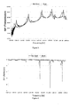
- Fig. 3 shows the transmission element S21 as a function of frequency and Fig. 4 shows the reflections from a single launcher/receiver system.
- rod antennas were on opposite sides of the trap as shown in Fig. 1 .
- the graph in Fig. 4 was created with a single antenna and the information is in the reflected signal.
- Fig. 5 is an expanded view of the transmission mode from Fig. 3 and shows detail around the mode near 1.7 GHz. One can readily see how the graph changes from no soot to soot. It is this difference that allows a determination of trap loading to be determined.
- the microwave sensing system disclosed herein can use inexpensive components with the microwave source being a modified microwave chip such as those used in cell phones, and the receiver can be a simple diode with or without amplification.
- the detection system can use advanced detection systems such as lock-in detection, heterodyne detection and others.
- any matter that builds in a substantial amount on the surface of a filter can be measured as long as it has a dielectric constant different from the background filter material (one in the case of air/engine exhaust).
- the system can be used to monitor the health of the trap. When substantial cracks are present in the system, soot distribution changes, and becomes inhomogeneous.
- the filtering monitoring system can be either original equipment, as well as be used as refrofits.
Landscapes
- Engineering & Computer Science (AREA)
- Chemical & Material Sciences (AREA)
- Combustion & Propulsion (AREA)
- Mechanical Engineering (AREA)
- General Engineering & Computer Science (AREA)
- Processes For Solid Components From Exhaust (AREA)
- Investigating Or Analyzing Materials By The Use Of Electric Means (AREA)
Claims (17)
- Procédé de détermination de la charge d'un filtre (24) ayant une première constante diélectrique avec un matériau contaminant ayant une seconde constante diélectrique qui diffère de la constante diélectrique du milieu qu'il déplace, le filtre (24) étant contenu à l'intérieur d'un récipient métallique (12, 14, 16),
caractérisé en ce que le récipient métallique (12, 14, 16) forme une cavité hyperfréquence et en ce que le procédé comprend :l'établissement d'une énergie hyperfréquence dans la cavité ;la surveillance de changements dans le facteur de qualité, Q, d'un mode résonnant dans la cavité hyperfréquence ; etla détermination de la charge du filtre sur la base des changements surveillés dans le facteur de qualité Q. - Procédé selon la revendication 1, dans lequel l'énergie hyperfréquence inclut de multiples modes de cavité permettant la détermination de la distribution spatiale de la charge de matériau contaminant.
- Procédé selon la revendication 1, dans lequel la réponse de la cavité hyperfréquence inclut en outre un décalage en fréquence d'un mode résonnant et un décalage en amplitude du signal hyperfréquence à la résonance.
- Procédé selon la revendication 1, incluant une antenne (26) utilisée en mode réflexion pour émettre/recevoir l'énergie hyperfréquence, ou dans lequel deux antennes (20, 22) sont utilisées en mode émission, une antenne émettant et l'autre antenne recevant.
- Procédé selon la revendication 1, incluant un guide d'ondes (28) utilisé en mode réflexion pour émettre/recevoir l'énergie hyperfréquence, ou dans lequel deux guides d'ondes sont utilisés en mode émission, un guide d'ondes émettant et l'autre guide d'ondes recevant.
- Procédé selon la revendication 1, dans lequel le filtre (24) est un piège à particules diesel pour éliminer la matière particulaire de l'échappement d'un moteur diesel ;
dans lequel le récipient métallique (12, 14, 16) inclut une partie cylindrique (12) entre deux cônes de transition (14, 16), l'un d'entre eux étant raccordé à un tuyau d'échappement (18) ; et
dans lequel le matériau du filtre est de la cordiérite ou du carbure de silicium. - Procédé selon la revendication 4, dans lequel au moins une antenne est une antenne tige (20) ou une antenne cadre (26).
- Procédé selon la revendication 6, dans lequel la matière particulaire est de la suie ou de la cendre.
- Procédé selon la revendication 1, dans lequel les deux modes de cavité d'ordre faible et d'ordre élevé sont utilisés pour surveiller la charge.
- Procédé selon la revendication 6, dans lequel la fréquence de fonctionnement est choisie de telle sorte que les modes fonctionnent au point de coupure au niveau de tuyaux d'entrée et de sortie à taille réduite du filtre (24).
- Procédé selon la revendication 4, dans lequel les deux antennes (20, 22) sont situées sur des côtés opposés du filtre ou sur le même côté du filtre ou, pour réduire au minimum la suie sur la surface des antennes (20, 22), les antennes sont situées sur le côté aval du filtre.
- Procédé selon la revendication 1, où l'énergie hyperfréquence est fournie par une puce hyperfréquence modifiée et est surveillée par une diode avec ou sans amplification.
- Procédé selon la revendication 1, dans lequel la surveillance utilise la détection synchrone ou la détection hétérodyne.
- Procédé selon la revendication 1, dans lequel un dispositif de surveillance hyperfréquence est utilisé pour déterminer la santé du filtre (24) par la détermination d'accumulation anormale de suie ou de cendre ou d'absence de celle-ci.
- Procédé selon la revendication 1, dans lequel un dispositif de surveillance hyperfréquence est utilisé pour déterminer la température du filtre (24) lorsque la constante diélectrique du filtre ou du matériau contaminant est une fonction de la température.
- Procédé selon la revendication 1, dans lequel un dispositif de surveillance hyperfréquence est utilisé pour déterminer la charge de cendre restante suite à la régénération du filtre.
- Système de détection de filtre hyperfréquence (10) comprenant une combinaison :d'un filtre (24) contenu à l'intérieur d'un logement (12, 14, 16) formant une cavité hyperfréquence ; etd'une ou de plusieurs antennes (20, 22) conçues pour surveiller les changements de réponse de cavité hyperfréquence, les changements étant relatifs à la charge du filtre,d'un générateur et d'un détecteur d'hyperfréquences utilisables pour déterminer les propriétés d'hyperfréquence de la cavité ; etde l'équipement électronique et du traitement des signaux associés aptes à déterminer la charge du filtre au moyen du procédé selon l'une quelconque des revendications précédentes.
Applications Claiming Priority (2)
| Application Number | Priority Date | Filing Date | Title |
|---|---|---|---|
| US74608106P | 2006-05-01 | 2006-05-01 | |
| PCT/US2007/067750 WO2007130896A2 (fr) | 2006-05-01 | 2007-04-30 | Détection hyperfréquence permettant de déterminer la charge de filtres |
Publications (3)
| Publication Number | Publication Date |
|---|---|
| EP2021813A2 EP2021813A2 (fr) | 2009-02-11 |
| EP2021813A4 EP2021813A4 (fr) | 2013-07-10 |
| EP2021813B1 true EP2021813B1 (fr) | 2014-08-27 |
Family
ID=38668468
Family Applications (1)
| Application Number | Title | Priority Date | Filing Date |
|---|---|---|---|
| EP07761557.3A Not-in-force EP2021813B1 (fr) | 2006-05-01 | 2007-04-30 | Détection hyperfréquence permettant de déterminer la charge de filtres |
Country Status (5)
| Country | Link |
|---|---|
| US (1) | US7679374B2 (fr) |
| EP (1) | EP2021813B1 (fr) |
| JP (1) | JP2009535647A (fr) |
| CN (1) | CN101438175B (fr) |
| WO (1) | WO2007130896A2 (fr) |
Cited By (1)
| Publication number | Priority date | Publication date | Assignee | Title |
|---|---|---|---|---|
| US9745909B2 (en) | 2015-10-01 | 2017-08-29 | Ford Global Technologies, Llc | Radio frequency control of air-fuel ratio |
Families Citing this family (37)
| Publication number | Priority date | Publication date | Assignee | Title |
|---|---|---|---|---|
| US8384396B2 (en) | 2006-05-01 | 2013-02-26 | Filter Sensing Technologies, Inc. | System and method for measuring retentate in filters |
| US8384397B2 (en) * | 2006-05-01 | 2013-02-26 | Filter Sensing Technologies, Inc. | Method and system for controlling filter operation |
| US8319183B2 (en) * | 2008-10-31 | 2012-11-27 | Corning Incorporated | Methods of characterizing and measuring particulate filter accumulation |
| CN102203392B (zh) * | 2008-11-03 | 2015-05-13 | 莱斯利·布朗伯格 | 用于测量过滤器中的滞留物的系统及方法 |
| US8650857B2 (en) * | 2009-01-16 | 2014-02-18 | GM Global Technology Operations LLC | Apparatus and method for onboard performance monitoring of exhaust gas particulate filter |
| US20100212299A1 (en) * | 2009-02-25 | 2010-08-26 | Jacob George | Methods for determining when to regenerate exhaust gas particulate filters |
| JP5562073B2 (ja) * | 2009-03-25 | 2014-07-30 | 日本碍子株式会社 | 粒子状物質の堆積量検出装置 |
| JP5568322B2 (ja) * | 2009-03-25 | 2014-08-06 | 日本碍子株式会社 | 粒子状物質の堆積量検出装置 |
| US20100266461A1 (en) * | 2009-04-16 | 2010-10-21 | Massachusetts Institute Of Technology | Method For Reducing Pressure Drop Through Filters, And Filter Exhibiting Reduced Pressure Drop |
| JP2010271303A (ja) * | 2009-04-22 | 2010-12-02 | Ngk Insulators Ltd | 粒子状物質の堆積量検出方法および装置 |
| WO2010138494A1 (fr) | 2009-05-26 | 2010-12-02 | Inentec Llc | Régénérateur pour épuration du gaz de synthèse et récupérateur d'énergie dans des systèmes gazéifieurs |
| US8283930B2 (en) * | 2009-09-29 | 2012-10-09 | General Electric Company | Method and system for compensating for variation in attenuation measurements caused by changes in ambient temperature |
| JP4798813B1 (ja) * | 2010-03-24 | 2011-10-19 | 日本碍子株式会社 | 粒子状物質の検出方法 |
| US8470070B2 (en) | 2010-07-22 | 2013-06-25 | Caterpillar Inc. | Ash detection in diesel particulate filter |
| US8669521B2 (en) * | 2010-09-24 | 2014-03-11 | Wisconsin Alumni Research Foundation | Microwave cavity detector for mass spectrometry |
| US8942887B2 (en) | 2010-12-16 | 2015-01-27 | Caterpillar Inc. | Machine, exhaust particulate filter system, and method |
| US9062576B2 (en) * | 2010-12-22 | 2015-06-23 | Caterpillar Inc. | Exhaust particulate filter system and operating method therefor |
| US8833063B2 (en) | 2011-05-17 | 2014-09-16 | Caterpillar Inc. | Methods and system for ash detection in exhaust particulate filter |
| US8875496B2 (en) | 2011-06-29 | 2014-11-04 | Caterpillar Inc. | Regeneration control system for exhaust filter and method |
| US8806852B2 (en) * | 2012-02-08 | 2014-08-19 | GM Global Technology Operations LLC | Method for controlling regeneration within an after-treatment component of a compression-ignition engine |
| DE102012105281A1 (de) * | 2012-06-18 | 2013-12-19 | Endress + Hauser Gmbh + Co. Kg | Füllstandsmessgerät und Vorrichtung zur Bestimmung der Dielektrizitätszahl |
| US9334772B2 (en) | 2012-10-29 | 2016-05-10 | Massachusetts Institute Of Technology | Particulate filter control system and method |
| WO2014173889A1 (fr) * | 2013-04-23 | 2014-10-30 | Basf Se | Procédé et dispositif pour la mesure de dépôts à l'intérieur d'un appareil par rayonnement micro-ondes |
| JP2017528783A (ja) | 2014-06-06 | 2017-09-28 | シーティーエス・コーポレーションCts Corporation | 高周波プロセス感知、制御、及び診断ネットワーク |
| CN112362973A (zh) * | 2014-06-06 | 2021-02-12 | 滤波器感知技术有限公司 | 射频状态变量测量系统和方法 |
| CN106794409A (zh) * | 2014-10-20 | 2017-05-31 | 滤波器感知技术有限公司 | 过滤器滞留物分析和诊断 |
| US9523303B2 (en) * | 2015-01-29 | 2016-12-20 | Ford Global Technologies, Llc | System and method for regenerating a particulate filter |
| GB201502317D0 (en) * | 2015-02-12 | 2015-04-01 | Delphi International Operations Luxembourg S.�.R.L. | Method for monitoring a particulate filter |
| US10118119B2 (en) * | 2015-06-08 | 2018-11-06 | Cts Corporation | Radio frequency process sensing, control, and diagnostics network and system |
| US10799826B2 (en) | 2015-06-08 | 2020-10-13 | Cts Corporation | Radio frequency process sensing, control, and diagnostics network and system |
| JP6533938B2 (ja) * | 2015-08-04 | 2019-06-26 | 株式会社Wadeco | 高炉内装入物の表面検出装置における粉塵付着状況の検知方法 |
| WO2017180466A1 (fr) * | 2016-04-11 | 2017-10-19 | Cts Corporation | Système à radiofréquence et procédé de surveillance de constituants d'échappement de sortie de moteur |
| US10436089B2 (en) * | 2017-01-18 | 2019-10-08 | Cummins Emission Solutions Inc. | Radio frequency sensor in an exhaust aftertreatment system |
| KR101984530B1 (ko) * | 2017-09-01 | 2019-06-03 | (주)맥솔루션 | 마이크로웨이브 신호를 이용한 물질 분석 장치 |
| WO2019143595A1 (fr) | 2018-01-16 | 2019-07-25 | Cts Corporation | Système de capteur radiofréquence incorporant un système et un procédé d'apprentissage automatique |
| CA3090087A1 (fr) | 2018-02-06 | 2019-08-15 | Exxonmobil Research And Engineering Company | Estimation de fraction/distribution de phase avec analyse de contraste dielectrique |
| US11733079B2 (en) | 2020-05-26 | 2023-08-22 | ExxonMobil Technology and Engineering Company | Measuring the flow rate of fluids with dielectric contrast analysis |
Family Cites Families (24)
| Publication number | Priority date | Publication date | Assignee | Title |
|---|---|---|---|---|
| US4042879A (en) * | 1975-11-03 | 1977-08-16 | Rockwell International Corporation | Microwave aerosol waterometer |
| US4024452A (en) * | 1976-03-10 | 1977-05-17 | Bell Telephone Laboratories, Incorporated | Integrated solid state isolator circuit |
| US4477771A (en) * | 1982-06-21 | 1984-10-16 | General Motors Corporation | Microwave detection of soot content in a particulate trap |
| SE8604605D0 (sv) * | 1985-10-25 | 1986-10-29 | Hughes Aircraft Co | Anordning for intrangsdetektering |
| JPH0781988B2 (ja) * | 1986-02-28 | 1995-09-06 | 新王子製紙株式会社 | シート状試料の磁気的異方性測定方法 |
| JPS63145951A (ja) * | 1986-12-09 | 1988-06-18 | Daipoole:Kk | 糸状材料の物性量測定装置 |
| GB8818463D0 (en) | 1988-08-03 | 1988-09-07 | Loughborough Consult Ltd | Apparatus & method for removing particulate matter from exhaust gases of i c engine |
| CA2078056C (fr) * | 1990-03-23 | 2002-07-30 | Nicholas George Cutmore | Dispositif et methode d'analyse de carbone dans les cendres volantes |
| CA2022702C (fr) * | 1990-08-03 | 1995-02-07 | Frank B. Walton | Methode et dispositif de detection de la concentration de suie dans un collecteur de particules |
| JPH04151569A (ja) * | 1990-10-15 | 1992-05-25 | Mitsubishi Heavy Ind Ltd | 広帯域電気材料定数測定装置 |
| JPH0750041B2 (ja) * | 1991-09-06 | 1995-05-31 | アトミック エナジー オブ カナダ リミテッド/エネルジイ アトミック デュ カナダ リミテ | 煤検出装置用アンテナシステム |
| US5142595A (en) * | 1991-10-21 | 1992-08-25 | Hughes Aircraft Company | Microwave system employing optically phased conformal antennas having photonic interconnects and method of forming photonic interconnects |
| DE4342505C1 (de) * | 1993-12-08 | 1995-04-27 | Stange Gerd | Verfahren und Vorrichtung zur Messung der Dielektrizitätskonstante von Probenmaterialien |
| US6183126B1 (en) * | 1994-04-11 | 2001-02-06 | The John Hopkins University | Method for nondestructive/noncontact microwave detection of electrical and magnetic property discontinuities in materials |
| US6147503A (en) * | 1998-05-08 | 2000-11-14 | The United States Of America As Represented By The Secretary Of Agriculture | Method for the simultaneous and independent determination of moisture content and density of particulate materials from radio-frequency permittivity measurements |
| US6507308B1 (en) * | 1999-08-12 | 2003-01-14 | Yupiteru Industries Co., Ltd. | Microwave detector |
| WO2004016916A1 (fr) * | 2002-08-13 | 2004-02-26 | Bosch Automotive Systems Corporation | Dispositif de commande de filtre |
| WO2004074670A2 (fr) | 2003-02-18 | 2004-09-02 | Cleaire Advanced Emission Controls, Llc. | Appareil de regeneration automatise et procede relatif a un filtre a particules |
| JP4048993B2 (ja) * | 2003-04-08 | 2008-02-20 | 日産自動車株式会社 | エンジンの排気浄化装置 |
| US20080048681A1 (en) * | 2004-02-12 | 2008-02-28 | Daimlerchrysler Ag | Device for Determining the State of a Soot Particle Filter |
| US20080092499A1 (en) * | 2004-09-14 | 2008-04-24 | Ngk Insulators Ltd | Porous Honeycomb Filter |
| US7157919B1 (en) * | 2005-07-26 | 2007-01-02 | Caterpillar Inc. | Method and system for detecting soot and ash concentrations in a filter |
| JP4956784B2 (ja) * | 2006-03-07 | 2012-06-20 | 日産自動車株式会社 | 排ガス浄化フィルタのパティキュレート堆積量検出装置及び検出方法 |
| JP4023514B1 (ja) * | 2006-09-07 | 2007-12-19 | 日新電機株式会社 | 粒子状物質除去装置 |
-
2007
- 2007-04-30 JP JP2009509990A patent/JP2009535647A/ja active Pending
- 2007-04-30 WO PCT/US2007/067750 patent/WO2007130896A2/fr not_active Ceased
- 2007-04-30 EP EP07761557.3A patent/EP2021813B1/fr not_active Not-in-force
- 2007-04-30 CN CN2007800157701A patent/CN101438175B/zh not_active Expired - Fee Related
- 2007-04-30 US US11/741,832 patent/US7679374B2/en active Active
Cited By (1)
| Publication number | Priority date | Publication date | Assignee | Title |
|---|---|---|---|---|
| US9745909B2 (en) | 2015-10-01 | 2017-08-29 | Ford Global Technologies, Llc | Radio frequency control of air-fuel ratio |
Also Published As
| Publication number | Publication date |
|---|---|
| WO2007130896A2 (fr) | 2007-11-15 |
| CN101438175A (zh) | 2009-05-20 |
| JP2009535647A (ja) | 2009-10-01 |
| WO2007130896A3 (fr) | 2008-04-24 |
| EP2021813A2 (fr) | 2009-02-11 |
| US7679374B2 (en) | 2010-03-16 |
| US20080059093A1 (en) | 2008-03-06 |
| CN101438175B (zh) | 2013-05-15 |
| EP2021813A4 (fr) | 2013-07-10 |
Similar Documents
| Publication | Publication Date | Title |
|---|---|---|
| US7679374B2 (en) | Microwave sensing for determination of loading of filters | |
| US9400297B2 (en) | System and method for measuring retentate in filters | |
| CN102203392B (zh) | 用于测量过滤器中的滞留物的系统及方法 | |
| US5497099A (en) | Antenna system for soot detecting | |
| US5157340A (en) | Method and apparatus for detecting soot concentration in particulate trap | |
| US7157919B1 (en) | Method and system for detecting soot and ash concentrations in a filter | |
| US4477771A (en) | Microwave detection of soot content in a particulate trap | |
| US11255799B2 (en) | Radio frequency state variable measurement system and method | |
| US8210033B2 (en) | Devices for detecting accumulation amount of particulates | |
| JP5562073B2 (ja) | 粒子状物質の堆積量検出装置 | |
| WO2011118669A1 (fr) | Procédé de détection de matières particulaires | |
| EP2246541B1 (fr) | Procédés et dispositifs pour détecter l'accumulation de particules | |
| WO2003029621A1 (fr) | Systeme a micro-ondes pour chauffer le filtre a carbure de silicium dans un systeme d'echappement de moteur diesel | |
| JP2010223169A (ja) | 粒子状物質の堆積量検出装置 | |
| JP2004226264A (ja) | アンテナ及び物体検出装置 | |
| JPH06307226A (ja) | フィルタの粒子状物質堆積密度分布検出方法および粒子状物質堆積密度分布検出装置 | |
| JP2010223165A (ja) | 粒子状物質の堆積量検出装置 | |
| SE529637C2 (sv) | Förfarande vid beredning, såsom läkemedelsberedning, beredningsanordning samt användning | |
| JPH06193428A (ja) | 排気フィルタのパティキュレート捕集量検出方法およびその装置 |
Legal Events
| Date | Code | Title | Description |
|---|---|---|---|
| PUAI | Public reference made under article 153(3) epc to a published international application that has entered the european phase |
Free format text: ORIGINAL CODE: 0009012 |
|
| 17P | Request for examination filed |
Effective date: 20081128 |
|
| AK | Designated contracting states |
Kind code of ref document: A2 Designated state(s): AT BE BG CH CY CZ DE DK EE ES FI FR GB GR HU IE IS IT LI LT LU LV MC MT NL PL PT RO SE SI SK TR |
|
| AX | Request for extension of the european patent |
Extension state: AL BA HR MK RS |
|
| RIN1 | Information on inventor provided before grant (corrected) |
Inventor name: WONG, VICTORC/O MASSACHUSETTS INSTITUTE OF TECHNOL Inventor name: PARKER, RONALDC/O MASSACHUSETTS INSTITUTE OF TECHN Inventor name: BROMBERG, LESLIEC/O MASSACHUSETTS INSTITUTE OF TEC Inventor name: KOERT, PETERC/O MASSACHUSETTS INSTITUTE OF TECHNOL Inventor name: SAPPOK, ALEXC/O MASSACHUSETTS INSTITUTE OF TECHNOL |
|
| RIN1 | Information on inventor provided before grant (corrected) |
Inventor name: PARKER, RONALD Inventor name: BROMBERG, LESLIE Inventor name: SAPPOK, ALEX Inventor name: KOERT, PETER Inventor name: WONG, VICTOR |
|
| DAX | Request for extension of the european patent (deleted) | ||
| A4 | Supplementary search report drawn up and despatched |
Effective date: 20130611 |
|
| RIC1 | Information provided on ipc code assigned before grant |
Ipc: F01N 9/00 20060101ALI20130605BHEP Ipc: G01R 27/04 20060101AFI20130605BHEP |
|
| GRAP | Despatch of communication of intention to grant a patent |
Free format text: ORIGINAL CODE: EPIDOSNIGR1 |
|
| INTG | Intention to grant announced |
Effective date: 20140313 |
|
| GRAS | Grant fee paid |
Free format text: ORIGINAL CODE: EPIDOSNIGR3 |
|
| GRAA | (expected) grant |
Free format text: ORIGINAL CODE: 0009210 |
|
| AK | Designated contracting states |
Kind code of ref document: B1 Designated state(s): AT BE BG CH CY CZ DE DK EE ES FI FR GB GR HU IE IS IT LI LT LU LV MC MT NL PL PT RO SE SI SK TR |
|
| REG | Reference to a national code |
Ref country code: GB Ref legal event code: FG4D |
|
| REG | Reference to a national code |
Ref country code: CH Ref legal event code: EP |
|
| REG | Reference to a national code |
Ref country code: CH Ref legal event code: NV Representative=s name: R. A. EGLI AND CO. PATENTANWAELTE, CH Ref country code: AT Ref legal event code: REF Ref document number: 684768 Country of ref document: AT Kind code of ref document: T Effective date: 20140915 |
|
| REG | Reference to a national code |
Ref country code: SE Ref legal event code: TRGR |
|
| REG | Reference to a national code |
Ref country code: IE Ref legal event code: FG4D |
|
| REG | Reference to a national code |
Ref country code: DE Ref legal event code: R096 Ref document number: 602007038318 Country of ref document: DE Effective date: 20141009 |
|
| REG | Reference to a national code |
Ref country code: AT Ref legal event code: MK05 Ref document number: 684768 Country of ref document: AT Kind code of ref document: T Effective date: 20140827 |
|
| REG | Reference to a national code |
Ref country code: LT Ref legal event code: MG4D |
|
| REG | Reference to a national code |
Ref country code: NL Ref legal event code: VDEP Effective date: 20140827 |
|
| PG25 | Lapsed in a contracting state [announced via postgrant information from national office to epo] |
Ref country code: GR Free format text: LAPSE BECAUSE OF FAILURE TO SUBMIT A TRANSLATION OF THE DESCRIPTION OR TO PAY THE FEE WITHIN THE PRESCRIBED TIME-LIMIT Effective date: 20141128 Ref country code: PT Free format text: LAPSE BECAUSE OF FAILURE TO SUBMIT A TRANSLATION OF THE DESCRIPTION OR TO PAY THE FEE WITHIN THE PRESCRIBED TIME-LIMIT Effective date: 20141229 Ref country code: BG Free format text: LAPSE BECAUSE OF FAILURE TO SUBMIT A TRANSLATION OF THE DESCRIPTION OR TO PAY THE FEE WITHIN THE PRESCRIBED TIME-LIMIT Effective date: 20141127 Ref country code: LT Free format text: LAPSE BECAUSE OF FAILURE TO SUBMIT A TRANSLATION OF THE DESCRIPTION OR TO PAY THE FEE WITHIN THE PRESCRIBED TIME-LIMIT Effective date: 20140827 Ref country code: ES Free format text: LAPSE BECAUSE OF FAILURE TO SUBMIT A TRANSLATION OF THE DESCRIPTION OR TO PAY THE FEE WITHIN THE PRESCRIBED TIME-LIMIT Effective date: 20140827 Ref country code: FI Free format text: LAPSE BECAUSE OF FAILURE TO SUBMIT A TRANSLATION OF THE DESCRIPTION OR TO PAY THE FEE WITHIN THE PRESCRIBED TIME-LIMIT Effective date: 20140827 |
|
| PG25 | Lapsed in a contracting state [announced via postgrant information from national office to epo] |
Ref country code: AT Free format text: LAPSE BECAUSE OF FAILURE TO SUBMIT A TRANSLATION OF THE DESCRIPTION OR TO PAY THE FEE WITHIN THE PRESCRIBED TIME-LIMIT Effective date: 20140827 Ref country code: CY Free format text: LAPSE BECAUSE OF FAILURE TO SUBMIT A TRANSLATION OF THE DESCRIPTION OR TO PAY THE FEE WITHIN THE PRESCRIBED TIME-LIMIT Effective date: 20140827 Ref country code: LV Free format text: LAPSE BECAUSE OF FAILURE TO SUBMIT A TRANSLATION OF THE DESCRIPTION OR TO PAY THE FEE WITHIN THE PRESCRIBED TIME-LIMIT Effective date: 20140827 Ref country code: IS Free format text: LAPSE BECAUSE OF FAILURE TO SUBMIT A TRANSLATION OF THE DESCRIPTION OR TO PAY THE FEE WITHIN THE PRESCRIBED TIME-LIMIT Effective date: 20141227 |
|
| PG25 | Lapsed in a contracting state [announced via postgrant information from national office to epo] |
Ref country code: NL Free format text: LAPSE BECAUSE OF FAILURE TO SUBMIT A TRANSLATION OF THE DESCRIPTION OR TO PAY THE FEE WITHIN THE PRESCRIBED TIME-LIMIT Effective date: 20140827 |
|
| PG25 | Lapsed in a contracting state [announced via postgrant information from national office to epo] |
Ref country code: CZ Free format text: LAPSE BECAUSE OF FAILURE TO SUBMIT A TRANSLATION OF THE DESCRIPTION OR TO PAY THE FEE WITHIN THE PRESCRIBED TIME-LIMIT Effective date: 20140827 Ref country code: SK Free format text: LAPSE BECAUSE OF FAILURE TO SUBMIT A TRANSLATION OF THE DESCRIPTION OR TO PAY THE FEE WITHIN THE PRESCRIBED TIME-LIMIT Effective date: 20140827 Ref country code: DK Free format text: LAPSE BECAUSE OF FAILURE TO SUBMIT A TRANSLATION OF THE DESCRIPTION OR TO PAY THE FEE WITHIN THE PRESCRIBED TIME-LIMIT Effective date: 20140827 Ref country code: RO Free format text: LAPSE BECAUSE OF FAILURE TO SUBMIT A TRANSLATION OF THE DESCRIPTION OR TO PAY THE FEE WITHIN THE PRESCRIBED TIME-LIMIT Effective date: 20140827 Ref country code: EE Free format text: LAPSE BECAUSE OF FAILURE TO SUBMIT A TRANSLATION OF THE DESCRIPTION OR TO PAY THE FEE WITHIN THE PRESCRIBED TIME-LIMIT Effective date: 20140827 |
|
| REG | Reference to a national code |
Ref country code: DE Ref legal event code: R097 Ref document number: 602007038318 Country of ref document: DE |
|
| PG25 | Lapsed in a contracting state [announced via postgrant information from national office to epo] |
Ref country code: PL Free format text: LAPSE BECAUSE OF FAILURE TO SUBMIT A TRANSLATION OF THE DESCRIPTION OR TO PAY THE FEE WITHIN THE PRESCRIBED TIME-LIMIT Effective date: 20140827 |
|
| PLBE | No opposition filed within time limit |
Free format text: ORIGINAL CODE: 0009261 |
|
| STAA | Information on the status of an ep patent application or granted ep patent |
Free format text: STATUS: NO OPPOSITION FILED WITHIN TIME LIMIT |
|
| 26N | No opposition filed |
Effective date: 20150528 |
|
| PG25 | Lapsed in a contracting state [announced via postgrant information from national office to epo] |
Ref country code: MC Free format text: LAPSE BECAUSE OF FAILURE TO SUBMIT A TRANSLATION OF THE DESCRIPTION OR TO PAY THE FEE WITHIN THE PRESCRIBED TIME-LIMIT Effective date: 20140827 Ref country code: LU Free format text: LAPSE BECAUSE OF FAILURE TO SUBMIT A TRANSLATION OF THE DESCRIPTION OR TO PAY THE FEE WITHIN THE PRESCRIBED TIME-LIMIT Effective date: 20150430 Ref country code: SI Free format text: LAPSE BECAUSE OF FAILURE TO SUBMIT A TRANSLATION OF THE DESCRIPTION OR TO PAY THE FEE WITHIN THE PRESCRIBED TIME-LIMIT Effective date: 20140827 |
|
| REG | Reference to a national code |
Ref country code: IE Ref legal event code: MM4A |
|
| REG | Reference to a national code |
Ref country code: FR Ref legal event code: PLFP Year of fee payment: 10 |
|
| PG25 | Lapsed in a contracting state [announced via postgrant information from national office to epo] |
Ref country code: IE Free format text: LAPSE BECAUSE OF NON-PAYMENT OF DUE FEES Effective date: 20150430 |
|
| PG25 | Lapsed in a contracting state [announced via postgrant information from national office to epo] |
Ref country code: BE Free format text: LAPSE BECAUSE OF FAILURE TO SUBMIT A TRANSLATION OF THE DESCRIPTION OR TO PAY THE FEE WITHIN THE PRESCRIBED TIME-LIMIT Effective date: 20140827 |
|
| REG | Reference to a national code |
Ref country code: DE Ref legal event code: R082 Ref document number: 602007038318 Country of ref document: DE Representative=s name: UEXKUELL & STOLBERG PARTNERSCHAFT VON PATENT- , DE Ref country code: DE Ref legal event code: R082 Ref document number: 602007038318 Country of ref document: DE Representative=s name: BIRD & BIRD LLP, DE |
|
| PG25 | Lapsed in a contracting state [announced via postgrant information from national office to epo] |
Ref country code: MT Free format text: LAPSE BECAUSE OF FAILURE TO SUBMIT A TRANSLATION OF THE DESCRIPTION OR TO PAY THE FEE WITHIN THE PRESCRIBED TIME-LIMIT Effective date: 20140827 |
|
| REG | Reference to a national code |
Ref country code: FR Ref legal event code: PLFP Year of fee payment: 11 |
|
| PG25 | Lapsed in a contracting state [announced via postgrant information from national office to epo] |
Ref country code: HU Free format text: LAPSE BECAUSE OF FAILURE TO SUBMIT A TRANSLATION OF THE DESCRIPTION OR TO PAY THE FEE WITHIN THE PRESCRIBED TIME-LIMIT; INVALID AB INITIO Effective date: 20070430 |
|
| REG | Reference to a national code |
Ref country code: DE Ref legal event code: R082 Ref document number: 602007038318 Country of ref document: DE Representative=s name: UEXKUELL & STOLBERG PARTNERSCHAFT VON PATENT- , DE |
|
| PG25 | Lapsed in a contracting state [announced via postgrant information from national office to epo] |
Ref country code: TR Free format text: LAPSE BECAUSE OF FAILURE TO SUBMIT A TRANSLATION OF THE DESCRIPTION OR TO PAY THE FEE WITHIN THE PRESCRIBED TIME-LIMIT Effective date: 20140827 |
|
| REG | Reference to a national code |
Ref country code: FR Ref legal event code: PLFP Year of fee payment: 12 |
|
| PGFP | Annual fee paid to national office [announced via postgrant information from national office to epo] |
Ref country code: FR Payment date: 20200427 Year of fee payment: 14 Ref country code: DE Payment date: 20200429 Year of fee payment: 14 Ref country code: CH Payment date: 20200504 Year of fee payment: 14 |
|
| PGFP | Annual fee paid to national office [announced via postgrant information from national office to epo] |
Ref country code: GB Payment date: 20200427 Year of fee payment: 14 Ref country code: IT Payment date: 20200423 Year of fee payment: 14 Ref country code: SE Payment date: 20200429 Year of fee payment: 14 |
|
| REG | Reference to a national code |
Ref country code: DE Ref legal event code: R119 Ref document number: 602007038318 Country of ref document: DE |
|
| REG | Reference to a national code |
Ref country code: SE Ref legal event code: EUG |
|
| GBPC | Gb: european patent ceased through non-payment of renewal fee |
Effective date: 20210430 |
|
| PG25 | Lapsed in a contracting state [announced via postgrant information from national office to epo] |
Ref country code: CH Free format text: LAPSE BECAUSE OF NON-PAYMENT OF DUE FEES Effective date: 20210430 Ref country code: LI Free format text: LAPSE BECAUSE OF NON-PAYMENT OF DUE FEES Effective date: 20210430 Ref country code: SE Free format text: LAPSE BECAUSE OF NON-PAYMENT OF DUE FEES Effective date: 20210501 Ref country code: DE Free format text: LAPSE BECAUSE OF NON-PAYMENT OF DUE FEES Effective date: 20211103 Ref country code: GB Free format text: LAPSE BECAUSE OF NON-PAYMENT OF DUE FEES Effective date: 20210430 Ref country code: FR Free format text: LAPSE BECAUSE OF NON-PAYMENT OF DUE FEES Effective date: 20210430 |
|
| PG25 | Lapsed in a contracting state [announced via postgrant information from national office to epo] |
Ref country code: IT Free format text: LAPSE BECAUSE OF NON-PAYMENT OF DUE FEES Effective date: 20200430 |